This document discusses the design of columns. It begins by defining different types of columns based on their effective length and how they support axial compressive loads. It then classifies columns based on their shape, slenderness ratio, secondary reinforcement, loading type, and materials used. The document outlines basic assumptions regarding maximum compressive strain and stresses. It provides equations to calculate the axial load capacity of columns with lateral ties or helical reinforcement. Finally, it presents the design steps for an axially loaded column and provides an example design problem for a short column.
![DESIGN OF COLUMNS
Theory
Compression members may be of three types:
1] Column: It is a vertical element used primarily to support axial compressive loads in the
direction parallel to longitudinal axis and having effective length greater than three times
LLD.
(See Cl. No. 25.1 P. no. 41)
Classification
1] On the basis of shape a) Rectangular, square, circular, any other geometric shape like L-
section, T-section, etc.)
2] On the basis of slenderness ratio a) Short column: le/LLD ≤12, b) Long Column: le/LLD >12
3] On the basis of secondary reinforcement a) laterally tied b) spirally (helically) Tied
4] On the basis of type of loading (supporting/ connecting beam) a) axially loaded b) Axial load
with Uni-axial bending c) Axial load with Bi-axial bending.
5] On the basis of materials used a) Timber b) steel c) Masonry d) RCC e) Steel f) Composite
Beam-1
Slab Beam-2
L=L1 L2 L= L1
FL FL
Flat slab
D (Drop)
L2 Where, L = Unsupported length of column
L1 = L
FL](https://image.slidesharecdn.com/sd-ii-all-column-20-230612054503-ed8f736c/85/SD-II-ALL-column-20-pdf-1-320.jpg)
![DESIGN OF COLUMNS
Theory
Compression members may be of three types:
1] Column: It is a vertical element used primarily to support axial compressive loads in the
direction parallel to longitudinal axis and having effective length greater than three times
LLD.
(See Cl. No. 25.1 P. no. 41)
Classification
1] On the basis of shape a) Rectangular, square, circular, any other geometric shape like L-
section, T-section, etc.)
2] On the basis of slenderness ratio a) Short column: le/LLD ≤12, b) Long Column: le/LLD >12
3] On the basis of secondary reinforcement a) laterally tied b) spirally (helically) Tied
4] On the basis of type of loading (supporting/ connecting beam) a) axially loaded b) Axial load
with Uni-axial bending c) Axial load with Bi-axial bending.
5] On the basis of materials used a) Timber b) steel c) Masonry d) RCC e) Steel f) Composite
Beam-1
Slab Beam-2
L=L1 L2 L= L1
FL FL
Flat slab
D (Drop)
L2 Where, L = Unsupported length of column
L1 = L
FL](https://image.slidesharecdn.com/sd-ii-all-column-20-230612054503-ed8f736c/75/SD-II-ALL-column-20-pdf-1-2048.jpg)
![Basic assumptions:
1) Max. Compressive strain ( €cc) in axial compression is 0.002.
2) €cc = €sc
3) The stress-strain curve of steel in compression is same as in tension.
Axial Load on Column
a) With lateral ties
Pu = 0.4fck.Ac + 0.67fyAsc
Ac = Ag – Asc
𝑃𝑢 = 0.4𝑓𝑐𝑘. 𝐴𝑔 + (0.67𝑓𝑦 – 0.40𝑓𝑐𝑘)𝐴𝑠𝑐
b) With Helical reinforcement
𝑃𝑢 = 1.05[0.4𝑓𝑐𝑘. 𝐴𝑔 + (0.67𝑓𝑦 – 0.40𝑓𝑐𝑘) 𝐴𝑠𝑐]
But 5% strength of column can be increase if the ratio of the volume of helical
reinforcement to the volume of core shall not be less than 0.36(Ag/Ac-1)fck/fy
i.e.
𝑉
𝑉𝑘
≥
0.36
𝐴𝑔
𝐴𝑐
−1 𝑓𝑐𝑘
𝑓𝑦
Vh = (length in one spiral X Area ) of helical reinforcement
Vh = (π.Dk)X (π/4)(Фsh)2
Vk = Area of core X pitch of helical reinforcement
Vk = (π Dk2
/4) Sp](https://image.slidesharecdn.com/sd-ii-all-column-20-230612054503-ed8f736c/85/SD-II-ALL-column-20-pdf-2-320.jpg)
![Design steps for Axially loaded column
Given: Pu, fck, fy, l, end conditions
Required: b, D, Ast, Ash,
1] Calculate load on column (Pc)
(Pc) = Load from slab + self weight of beam + self weight of wall
+ self weight of column
Design Load on column (Pu) = 1.5 Pc
2] Assume % of steel provided in column (p) = 1.5% (0.8-4%)
3] Calculate Ag
Ag = Pu /[0.4Fck + (0.67fy -0.4fck) p]
4] Assume width of column, find D
Ag = b X D
5] Check slenderness ratio
If
𝑙𝑒
𝐿𝐿𝐷
≤ 12 then the column is short
6] Check for minimum eccentricity
exmin = L/500 + D/30 or 20 mm < 0.05D
eymin = L/500 + b/30 or 20mm < 0.05b
7] Calculate Asc
Asc = p X bD/100)
Assume diameter and find nos.
8] Calculate Ash
For column with lateral ties
a) Diameter of Lateral ties (Фsh) = ¼ (Фmax) or 6mm whichever is more
b) Spacing of later ties (Sp) = LLD or 16XФmin or 300mm whichever is less
For circular column with helical reinforcement
a) Diameter of helical reinforcement (Фsh) = i) ¼ (Фmax)
ii) 6mm, whichever is greater
b) Pitch of helical reinforcement (Sp) > 25mm or 3 X Фsh
< 75mm or (1/6 )X Dk
9] Reinforcement details](https://image.slidesharecdn.com/sd-ii-all-column-20-230612054503-ed8f736c/85/SD-II-ALL-column-20-pdf-3-320.jpg)
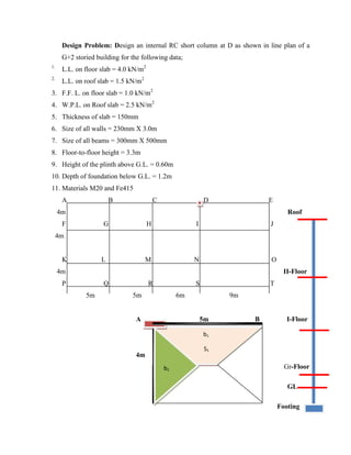
![1] Load calculation
a) Load of Roof slab : i) DL ii) WPL iii) WL
3.75 + 2.5 +1.5 = 7.75 kN/m2
b) Load of Floor slab : i) DL ii) FFL iii) WL
3.75 + 1.0 +4.0 = 8.75 kN/m2
c) Self weight of Beam : b X D X 25
0.300 X 0.500 X 25 = 3.75 kN/m
d) Self weight of Wall : t X H X 20
0.230 X 3.0 X 20 = 13.80kN/m
e) Self weight of Column : b X D X L X 25
0.300 X 0.500 X 3.3 X 25 = 9.90 kN
f) Self weight of Column below plinth : b X D X L X 25
0.300 X 0.500 X (0.6 +1.2) X 25 = 5.40 kN
2] Load on Column = Load from Top column if any + Load from slab
+ Load from beam + Load from wall + self weight of column
= (Pc)above column + (Slab load X area of slab under column)
+ (Beam load X Length of all beam connected to column)/2
+ (Wall load X Length of all walls connected to column)/2
+ (Self weight of column)
(Pc)Top column = 0 + 7.75 X (4X5) + 3.75 X (4 +5) + 0 + 9.90
= 198.65 kN
(Pc)Intermediate column = 198.65 + 8.75 X (4X5) + 3.75 X (4 +5) + 13.80 X (4 +5)
+ 9.90
= 541.50 kN
(Pc)Ground column = 541.50 + 8.75 X (4X5) + + 3.75 X (4 +5) + 13.80 X (4 +5)
+ 9.90
= 884.35 kN
(Pc) column Below GL = 884.35 + 0 + 3.75 X (4 +5) + 13.80 X (4 +5) + 5.40
= 1047.70 kN
A] Design column below plinth level
1] (Pc)0 = 1047.70 kN, Design load Pu =1.5 Pc = 1571.55kN](https://image.slidesharecdn.com/sd-ii-all-column-20-230612054503-ed8f736c/85/SD-II-ALL-column-20-pdf-5-320.jpg)
![2] Assume % of steel provided in column (p) = 1.5% ------------(0.8-4%)
3] Calculate Ag
Ag = Pu /[0.4Fck + (0.67fy -0.4fck) p]
Ag = 1571.55X103
/[0.4X20 + (0.67X415 – 0.4X20)X0.015]
Ag = 130410.97mm2
4] Assume width of column as 300mm, find D
Ag = b X D
D = 434.70mm
Consider b X D = 300mm X 450mm
5] Check slenderness ratio
le/LLD = 1.5 l / 300 = 1.5 X 1800/300 = 9 ------------------≤12
the column is short
6] Check for minimum eccentricity
exmin = L/500 + D/30 or 20 mm < 0.05D
exmin = 1800/500 + 450/30 or 20 mm = 18.6 or 20mm < 0.05D (22.5mm) ok!
eymin = L/500 + b/30 or 20mm < 0.05b
eymin = 1800/500 + 300/30 or 20mm = 13.6 or 20mm < 0.05b (15mm)
7] Calculate Asc
Asc = p X Ag/100)
=1.5/100 (130410.97) =1956.16 mm2
≥ (Asc) min =
𝟎.𝟖.𝒃.𝑫
𝟏𝟎𝟎
= 𝟏𝟐𝟎𝟎 𝒎𝒎𝟐
≤ (Asc)max = =
𝟒.𝒃.𝑫
𝟏𝟎𝟎
= 𝟔𝟎𝟎𝟎 𝒎𝒎𝟐
Ok!
Assume 20mm# diameter as longitudinal reinforcement.
Nos. =
𝐴𝑠𝑐
𝑎𝑠𝑐
=
1956.16
314
= 6.23 𝑁𝑜𝑠.
So, Provide 6#20mm and 2#12mm as longitudinal reinforcement
7] Calculate Ash
a) Diameter of Lateral ties (Фsh) = i) ¼ (Фmax) = ¼ X20 = 5mm
ii) 6mm whichever is more
= 6mm
b) Spacing of later ties (Sp) = i) LLD = 300mm](https://image.slidesharecdn.com/sd-ii-all-column-20-230612054503-ed8f736c/85/SD-II-ALL-column-20-pdf-6-320.jpg)
![ii) 16XФmin =16 X 12 192 mm
iii) 300mm whichever is less
= 190 mm
Provide 6mmФ @190mm c/c as lateral ties
8] Reinforcement details D = 450mm
40
b 300mm
6#20 + 2#12 (Longitudinal reinf.)
6Ф @ 190mm c/c (Lateral Ties)](https://image.slidesharecdn.com/sd-ii-all-column-20-230612054503-ed8f736c/85/SD-II-ALL-column-20-pdf-7-320.jpg)
![Design of Axially loaded column with uni-axial bending
Load on column are rarely axial.
Due to non-homogeneity of materials, inaccuracy in loading, accidental load, etc.
Therefore it is recommends that every compression member should be designed for certain
minimum eccentricity.
If this emin ≥ 0.05D, then the column may be designed as axially loaded as axially column.
But if this criteria is not satisfied then the column has to be designed for axial load (Pu) and
moment (Mu = emin Pu).
Besides this, many times column is subjected to (1) eccentric load or (2) end moments due to
monolithic connection of beams with columns. Such a column is subjected to either uniaxial
moments or biaxial moments in addition to axial load.
Side columns are not only subjected to direct loads (P), but also moments (M) due to
eccentricity in application of loads (ex. Beams are along three sides) and therefore moments
developed only along one side. Such beams are said to be under Uniaxial bending.
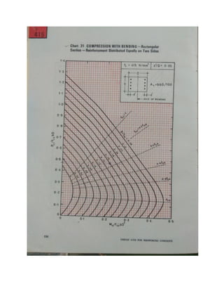
Analysis by charts (SP 16)
Given: Pu, fck, fy, le, end conditions, Mux or Muy
Required: Ast, Ash, b, D
A] Bisecting the depth of Column (i.e. bending @ X-X axis/ major axis)
1] Assume size of column (b X D)
2] Calculate Pu/fckbD
3] Calculate Mu/fckbD2
4] Calculate dc’/D
5] From the chart given in SP 16, depending on dc’/D, grade of steel (fy), obtained the
point of intersection of Pu/fckbD & Mu/fckbD2
and interpolate the value of p/fck
6] Calculate Asc
Asc = (p X bD/100) ≥ (Asc)min
Assume diameter of longitudinal reinforcement find Nos.
7] Calculate Ash
a) Diameter of Lateral ties (Фsh) = ¼ (Фmax) or 6mm whichever is more
b) Spacing of later ties (Sp) = a) L.L.D.](https://image.slidesharecdn.com/sd-ii-all-column-20-230612054503-ed8f736c/85/SD-II-ALL-column-20-pdf-8-320.jpg)
![b) 16XФmin
c) 300mm whichever is less
8] Reinforcement details
B] Bisecting the width of Column (i.e. bending @ Y-Y axis/ minor axis)
1] Assume size of column (b X D)
2] Calculate Pu/fckbD
3] Calculate Mu/fckDb2
4] Calculate dc’/b
5] From the chart given in SP 16, depending on dc’/b, grade of steel (fy), obtained the
point of intersection of Pu/fckbD & Mu/fckb2
D and interpolate the value of p/fck
6] Calculate Asc
Asc = (p X bD/100) ≥ (Asc)min
Assume diameter of longitudinal reinforcement find Nos.
7] Calculate Ash
a) Diameter of Lateral ties (Фmin) = ¼ (Фmax) or 5mm whichever is more
b) Spacing of later ties (Sp) = L.L.D. or 16XФmin or 300mm whichever is less
8] Reinforcement details](https://image.slidesharecdn.com/sd-ii-all-column-20-230612054503-ed8f736c/85/SD-II-ALL-column-20-pdf-9-320.jpg)
![1] Load calculation
a) Load of Roof slab : i) DL ii) WPL iii) WL
3.75 + 2.5 +1.5 = 7.75 kN/m2
b) Load of Floor slab : i) DL ii) FFL iii) WL
3.75 + 1.0 +4.0 = 8.75 kN/m2
c) Self weight of Beam : b X D X 25
0.300 X 0.500 X 25 = 3.75 kN/m
d) Self weight of Wall : t X H X 20
0.230 X 3.0 X 20 = 13.80kN/m
e) Self weight of Column : b X D X L X 25
0.300 X 0.500 X 3.3 X 25 = 9.90 kN
f) Self weight of Column below plinth: b X D X L X 25
0.300 X 0.500 X (0.6 +1.2) X 25 = 5.40 kN
2] Load on floor beams
(b1) = Self weight of beam + Load from slab (S1)+ Load from wall
= Wb + 𝑊
𝑠. 𝑙𝑒𝑥 (
𝛽
(2.𝛽+1)
) + Ww
3.75 + 8.75X4 𝑋(
1.5
2𝑋1.5+1
) + 13.80
Wb1 = 30.675 kNm
(b2) = Self weight of beam + Load from slab (S2) + Load from wall
= Wb + 𝑊
𝑠. 𝑙𝑒𝑥 /2 + Ww
3.75 +
8.75𝑋4
2
+ 13.80
Wb2 = 35.05 kNm
(b3) = Self weight of beam + Load from slab (S1 & S2) + Load from wall
= Wb + 𝑊
𝑠.
𝑙𝑒𝑥
3
+ WsX0 + Ww
= 3.75 +
8.75𝑋4
3
+ 0 + 13.80
Wb3 = 29.22 kNm
3] Load on Column = Load from Top column if any + Shear/ support reaction from
Beams
(b1, b2 & b3) + (Self weight of column)](https://image.slidesharecdn.com/sd-ii-all-column-20-230612054503-ed8f736c/85/SD-II-ALL-column-20-pdf-11-320.jpg)
![(Pc)Top column = (Pc)above + 𝑊𝑏. 𝑙𝑒/2 + (Pc)self
0 + (30.675X6/2) + (35.05X9/2) + (29.22X4/2) + 9.90
= 0 + 92.01 + 157.725 + 58.44 + 9.90
= 318.75 kN
(Pc)Intermediate column = 318.75 + 92.01 + 157.725 + 58.44 + 9.90 +
= 637.50 kN
(Pc)Ground column = 637.50 + 92.01 + 157.725 + 58.44 + 9.90
= 936.25 kN
(Pc) column Below GL = 936.25 + + 201.82 + 5.40
= 1143.47 kN
A] Design column at ground level
1] (Pc)Gr = 936.25 kN, Design load Pu =1.5 Pc = 1404.375 kN
2] Assume size of column bXD = 230mm X 500mm
3] Check slenderness ratio
le/LLD = 0.65XL / 300 = 0.65 X 3000/300 = 6.5 ------------------≤12
Therefore column is design as short column
4] Calculate minimum eccentricity & moments
exmin = L/500 + D/30 or 20 mm < 0.05D
exmin = 3000/500 + 400/30 or 20 mm = 19.33 or 20mm , = 20mm
Muxmin = exmin.Pu = 20X1404.375/1000 = 28.087 kNm
eymin = L/500 + b/30 or 20mm < 0.05b
eymin = 3000/500 + 300/30 or 20mm = 16 or 20mm, = 20mm
Muymin = eymin.Pu = 20X1404.375/1000 = 28.087 kNm
5] Moment on columns
a) along x-x axis (i.e. bisecting the depth of column)
Mx =
𝐾𝑐
(𝐾𝑐+
𝐾𝑏
2
)
𝑋 𝐹𝑀𝑏
𝐾𝑐
(𝐾𝑐+
𝐾𝑏 1
2
+
𝑘𝑏 2
2
+
𝐾𝑏 3
2
)
𝑋 (𝑀𝑓𝑏2 − 𝑀𝐹𝑏1)
Ic = b.D3
/12 = 300X5003
/12 = 3.125 X10⁹
mm4
,
Kc = Ic/L = 3.125X10⁹
/3000 =1.042X10⁶
Kb = b.D3
/12 = 300X5003
/12 = 3.125X10⁹
mm4
,
Kb = Ib/L
Kb1 = Ib/L1 = 3.125X10⁹
/6000 = 5.20X10⁵
,](https://image.slidesharecdn.com/sd-ii-all-column-20-230612054503-ed8f736c/85/SD-II-ALL-column-20-pdf-12-320.jpg)
![Kb2 = Ib/L2 = 3.125X10⁹
/9000 = 3.47X10⁵
,
Kb3 = Ib/L3 = 3.125X10⁹
/4000 = 7.81X10⁵,
𝑀𝐹𝑏1 =
𝑊𝑏.𝑙𝑒 2
12
=
30.67𝑋62
12
= 92.025 𝑘𝑁𝑚
𝑀𝐹𝑏2 =
𝑊𝑏.𝑙𝑒 2
12
=
35.0.5𝑋92
12
= 236.59 𝑘𝑁𝑚
𝑀𝐹𝑏3 =
𝑊𝑏.𝑙𝑒 2
12
=
29.22𝑋42
12
= 38.96 𝑘𝑁𝑚
Mx =
𝐾𝑐
(𝐾𝑐+
𝐾𝑏 1
2
+
𝑘𝑏 2
2
+
𝐾𝑏 3
2
)
𝑋 (𝑀𝑓𝑏2 − 𝑀𝐹𝑏1)
=
10.42𝑋105
(10.42𝑋105 +
5.20𝑋105
2
+
3.47𝑋105
2
+
7.81𝑋105
2
)
𝑋 (236.59 − 92.025)
= 0.5584 X 144.565
= 80.73 kNm
Mux= 1.5 Mx = 1.5 X 80.73 = 121.09 kNm > Mumin =28.085 kNm
My =
𝐾𝑐
(𝐾𝑐+
𝐾𝑏 1
2
+
𝑘𝑏 2
2
+
𝐾𝑏 3
2
)
𝑋 (𝑀𝑓𝑏3)
= 0.5584 X 38.96
= 21.75 kNm
As Muy < Muymin = 28.087 kNm
So, design column with uniaxial bending along XX axis i.e. bisecting depth.
Bisecting the depth of Column (i.e. bending @ X-X axis/ major axis)
1] Calculate Pu/fck.bD
𝑃𝑢
𝐹𝑐𝑘.𝑏.𝐷
=
1404.375𝑋1000
20𝑋300𝑋500
= 0.468
2] Calculate Mu/fckbD2
𝑀𝑢𝑥
𝐹𝑐𝑘.𝑏.𝐷2
=
121.09𝑋106
20𝑋300𝑋5002
= 0.081
3] Calculate d’/D
𝑑′
𝐷
=
50
500
= 0.10
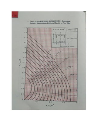
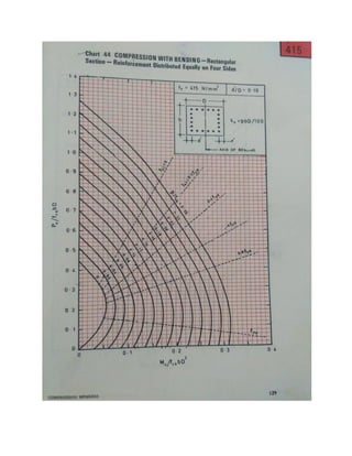
4] From the chart given in SP 16, Chart no.44, depending on dc’/D, grade of steel (fy),
obtained the point of intersection of Pu/fckbD & Mu/fckbD2
and interpolate the value of
p/fck, Assume equal distribution of reinforcement.](https://image.slidesharecdn.com/sd-ii-all-column-20-230612054503-ed8f736c/85/SD-II-ALL-column-20-pdf-13-320.jpg)
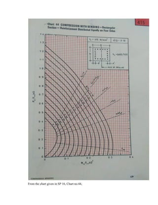
![𝑑𝑐′
𝐷
Pu/fck.bD Mu/fckbD2
p/fck
0.10 0.468 0.081 0.08
p/fck = 0.08
p = 0.08X20 = 1.60
p = Asc/bD
Asc = p.bD/100 = 1.6X300X500/100 = 2400 mm2
Assume #20 mm as longitudinal reinforcement, find Nos.
Nos. =
2400
314
= 7.64
Provide 8#20 as longitudinal reinforcement.
7] Calculate Ash
a) Diameter of Lateral ties (Фsh) = ¼ (Фmax) = i) ¼ (20) = 5 mm
ii) 6mm, whichever is greater,
So take (Фsh) = 6mm
b) Spacing of later ties (Sp) = a) L.L.D. = 300 mm
b) 16XФmin = 16 X 20 = 320 mm
c) 300mm , whichever is less
So, provide #8 @ 300 mm C/C as lateral ties
8] Reinforcement details D = 500mm
40
b 300mm
8#20 (Longitudinal reinf.)
6Ф @ 300mm c/c (Lateral Ties)](https://image.slidesharecdn.com/sd-ii-all-column-20-230612054503-ed8f736c/85/SD-II-ALL-column-20-pdf-15-320.jpg)
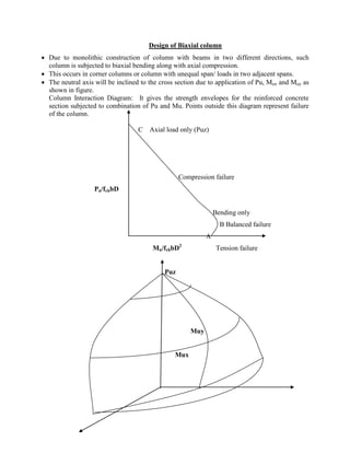
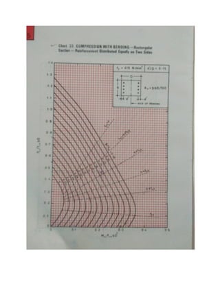
![Analysis by charts (SP 16)
Given: Pu, fck, fy, le, end conditions, Mux and Muy
Required: bXD, Ast, Ash
1] Assume size of column (b X D), p and its distribution
2] Calculate Puz
Puz = 0.45fck.Ac + 0.75fy.Asc
3] Calculate Pu/Puz
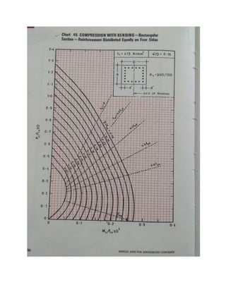
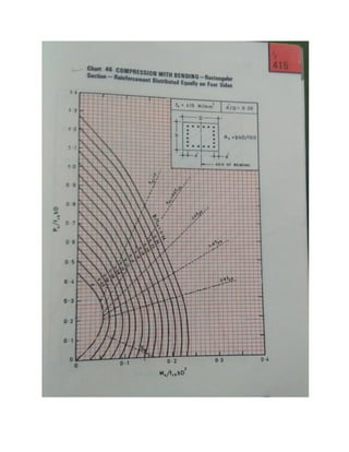
4] Calculate Mux1 -Bisecting the depth of Column (i.e. bending @ X-X axis
a) Calculate d’/D
b) Calculate p/fck
c) Calculate Pu/fckbD
d) From the chart given in SP 16, depending on d’/D, grade of steel (fy), obtained the
point of intersection of Pu/fckbD & p/fck and take the value Mu/fckbD2
i.e. Mux1 = ( ) fck.b.D2
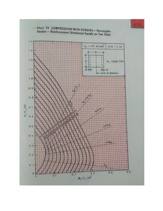
5] Calculate Muy1 Bisecting the width of Column (i.e. bending @ Y-Y axis respectively)
a) Calculate dc’/b
b) Calculate p/fck
c) Calculate Pu/fckbD
d) From the chart given in SP 16, depending on dc’/b, grade of steel (fy), obtained
the point of intersection of Pu/fckbD & p/fck and take the value Mu/fckb2
D
i.e. Muy1 = ( )fck.b2
D
6] Check
[
𝑀𝑢𝑥
𝑀𝑢𝑥1
]𝛼𝑛
+ [
𝑀𝑢𝑦
𝑀𝑢𝑦1
]𝑎𝑛
≤ 1 (safe)
7] Calculate (pbD/100)
8] Calculate Ash
a) Diameter of Lateral ties (Фmin) = ¼ (Фmax) or 5mm whichever is more
b) Spacing of later ties (Sp) = L.L.D. or 16XФmin or 300mm whichever is less
9] Reinforcement details](https://image.slidesharecdn.com/sd-ii-all-column-20-230612054503-ed8f736c/85/SD-II-ALL-column-20-pdf-17-320.jpg)
![1] Load calculation
a) Load of Roof slab : i) DL ii) WPL iii) WL
3.75 + 2.5 +1.5 = 7.75 kN/m2
b) Load of Floor slab : i) DL ii) FFL iii) WL
3.75 + 1.0 +4.0 = 8.75 kN/m2
c) Self weight of Beam : b X D X 25
0.300 X 0.500 X 25 = 3.75 kN/m
d) Self weight of Wall : t X H X 20
0.230 X 3.0 X 20 = 13.80kN/m
e) Self weight of Column : b X D X L X 25
0.300 X 0.500 X 3.3 X 25 = 9.90 kN
f) Self weight of Column below plinth: b X D X L X 25
0.300 X 0.500 X (0.6 +1.2) X 25 = 5.40 kN
2] Load on floor beams
(b1) = Self weight of beam + Load from slab (S1)+ Load from wall
= Wb + 𝑊
𝑠. 𝑙𝑒𝑥 (
𝛽
(2.𝛽+1)
) + Ww
3.75 + 8.75X4 𝑋(
1.5
2𝑋1.5+1
) + 13.80
Wb1 = 30.675 kNm
(b2) = Self weight of beam + Load from slab (S1) + Load from wall
= Wb + 𝑊
𝑠.
𝑙𝑒𝑥
3
+ Ww
3.75 +
8.75𝑋4
3
+ 0 + 13.80
Wb2 = 29.22 kNm
3] Load on Column = Load from Top column if any + Shear/ support reaction from
Beams
(b1 & b2 ) + (Self weight of column)
(Pc)Top column = (Pc)above + 𝑊𝑏. 𝑙𝑒/2 + (Pc)self
0 + (30.675X5/2) + (29.22X4/2) + 9.90
= 0 + 76.687 + 58.44 + 9.90
145.03 kN](https://image.slidesharecdn.com/sd-ii-all-column-20-230612054503-ed8f736c/85/SD-II-ALL-column-20-pdf-19-320.jpg)
![(Pc)Intermediate column = 145.03 + 145.03
= 290.05 kN
(Pc)Ground column = 290.05 + 145.05
= 435.10 kN
(Pc) column Below GL = 435.10 + 78.975 + 5.40
= 519.475 kN
A] Design column below ground level
1] (Pc)Gr = 519.475 kN, Design load Pu =1.5 Pc = 779.21 kN
2] Assume size of column bXD = 300mm X 500mm
3] Check slenderness ratio
le/LLD = 1.2XL / 300 = 1.2X 1.8/300 = 7.2------------------≤12
the column is short
4 Calculate minimum eccentricity & moments
exmin = L/500 + D/30 or 20 mm < 0.05D
exmin = 1800/500 + 500/30 or 20 mm = 20.26 or 20mm , take 20.26mm
Muxmin = exmin.Pu = 20.26X779.21/1000 = 15.78 kNm
eymin = L/500 + b/30 or 20mm < 0.05b
eymin = 1800/500 + 300/30 or 20mm = 13.60 or 20mm, = 20mm
Muymin = eymin.Pu = 20X779.21/1000 = 15.58 kNm
4] Moment on columns
a) along x-x axis (i.e. bisecting the depth of column)
Mx =
𝐾𝑐
(𝐾𝑐+
𝐾𝑏
2
)
𝑋 𝐹𝑀𝑏
𝐾𝑐
(𝐾𝑐+
𝐾𝑏 1
2
+
𝑘𝑏 2
2
)
𝑋 (𝑀𝑓𝑏1)
Ic = b.D3
/12 = 300X5003
/12 = 3.125 X10⁹
mm4
,
Kc = Ic/L = 3.125X10⁹
/1800 =17.36X10⁵
Kb = b.D3
/12 = 300X5003
/12 = 3.125X10⁹
mm4
,
Kb = Ib/L
Kb1 = Ib/L1 = 3.125X10⁹
/5000 = 6.25X10⁵
, 𝑀𝐹𝑏1 =
𝑊𝑏.𝑙𝑒 2
12
=
30.67𝑋52
12
= 63.89 𝑘𝑁𝑚
Kb2 = Ib/L2 = 3.125X10⁹
/4000 = 7.81X10⁵,
𝑀𝐹𝑏2 =
𝑊𝑏.𝑙𝑒 2
12
=
29.22𝑋42
12
= 38.96 𝑘𝑁𝑚
Mx =
𝐾𝑐
(𝐾𝑐+
𝐾𝑏 1
2
+
𝑘𝑏 2
2
)
𝑋 𝑀𝐹𝑏1](https://image.slidesharecdn.com/sd-ii-all-column-20-230612054503-ed8f736c/85/SD-II-ALL-column-20-pdf-20-320.jpg)
![=
17.36𝑋105
(17.36𝑋105 +
6.25𝑋105
2
+
7.81𝑋105
2
)
𝑋 (63.89)
= 0.711 X 63.89
= 45.42 kNm
Mux= 1.5 Mx = 1.5 X 45.42 = 68.14 kNm > Mumin = 15.78 kNm
My =
𝐾𝑐
(𝐾𝑐+
𝐾𝑏 1
2
+
𝑘𝑏 2
2
)
𝑋 (𝑀𝑓𝑏2)
= 0.711 X 38.96
= 27.70 kNm
As Muy < Muymin = 15.58 kNm
So, design column subjected to axial load with Bi-axial bending.
1] Assume size of column (b X D) = 300mm X 500mm
2] Assume p = 2%, i.e. Asc = (2/100)Ag and reinforcement equally distributed among all
four sides.
3] Calculate Puz
Puz = 0.45fck.Ac + 0.75fy.Asc
Ag = Ac + Asc
Puz = 0.45fck.Ag + (0.75fy – 0.45fck)Asc
= 0.45X20X(300X500) + (0.75X415 -0.45X20)X(2/100)X(300X500)
Puz =2256.75 kN
3] Calculate Pu/Puz
779.21/2256.75 = 0.345
4] Find 𝛼𝑛,
Pu/Puz 𝛼𝑛
0.20 1.0
0.80 2.0
𝛼𝑛 = 1 +
2 − 1
0.8 − 02
𝑋 0.345 − 0.2 = 1.24
4] Calculate Mux1 -Bisecting the depth of Column (i.e. bending @ X-X axis
e) Calculate d’/D](https://image.slidesharecdn.com/sd-ii-all-column-20-230612054503-ed8f736c/85/SD-II-ALL-column-20-pdf-21-320.jpg)
![50/500 = 01
f) Calculate p/fck
2/20 =0.10
g) Calculate Pu/fckbD
779.21𝑋103
20𝑋300𝑋500
= 0.259
h) From the chart given in SP 16, depending on dc’/D, grade of steel (fy), obtained the
point of intersection of Pu/fckbD & p/fck and take the value Mu/fckbD2
= 0.14
i.e. Mux1 = ( 0.14) fck.b.D2
0.14X 20X300X5002
= 210 kNm
5] Calculate Muy1 Bisecting the width of Column (i.e. bending @ Y-Y axis respectively)
e) Calculate dc’/b
50/ 300 = 0.167
f) Calculate p/fck = 2/20 = 0.10
g) Calculate Pu/fckbD = 0.259
h) From the chart given in SP 16, depending on dc’/b, grade of steel (fy), obtained
the point of intersection of Pu/fckbD & p/fck and take the value Mu/fckb2
D = 0.08
i.e. Muy1 = ( 0.08)fck.b2
D = 72 kNm
6] Check
[
𝑀𝑢𝑥
𝑀𝑢𝑥1
]𝛼𝑛
+ [
𝑀𝑢𝑦
𝑀𝑢𝑦 1
]𝛼𝑛
≤ 1
[
68.14
210
]1.24
+ [
27.17
72
]1.24
= 0.247 + 0.298 = 0.545 ≤ 1 (safe)
7] Calculate Asc = (pbD/100)
Asc = 2X300X500/100 = 3000 mm2
Assume #25 mm diameter bars
Nos = 3000/490.63 = 6.11 Nos.
So, provide 4#25 + 4#20mm as longitudinal reinforcements
(Asc provided = 4X 490.625 + 4X314 =3281 mm2
) ok!
8] Calculate Ash
a) Diameter of Lateral ties
(Фmin) = ¼ (Фmax) = ¼ (25) = 6.26 mm or 6mm whichever is more, take 8mm
b) Spacing of later ties (Sp) = L.L.D. = 300mm
16XФmin =16X20 =320mm](https://image.slidesharecdn.com/sd-ii-all-column-20-230612054503-ed8f736c/85/SD-II-ALL-column-20-pdf-22-320.jpg)
![300mm, whichever is less
Consider 300mm
So, provide #8@300mm c/c as later ties
9] Reinforcement details
8] Reinforcement details
D = 500mm
40 300mm
b
4#25 + 4#20 (Longitudinal reinf.)
#8 @ 300mm c/c (Lateral Ties)](https://image.slidesharecdn.com/sd-ii-all-column-20-230612054503-ed8f736c/85/SD-II-ALL-column-20-pdf-23-320.jpg)