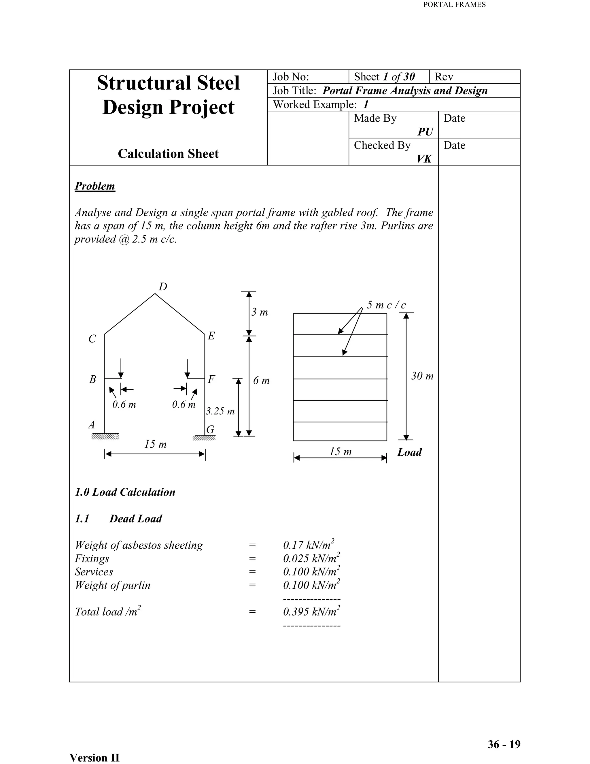
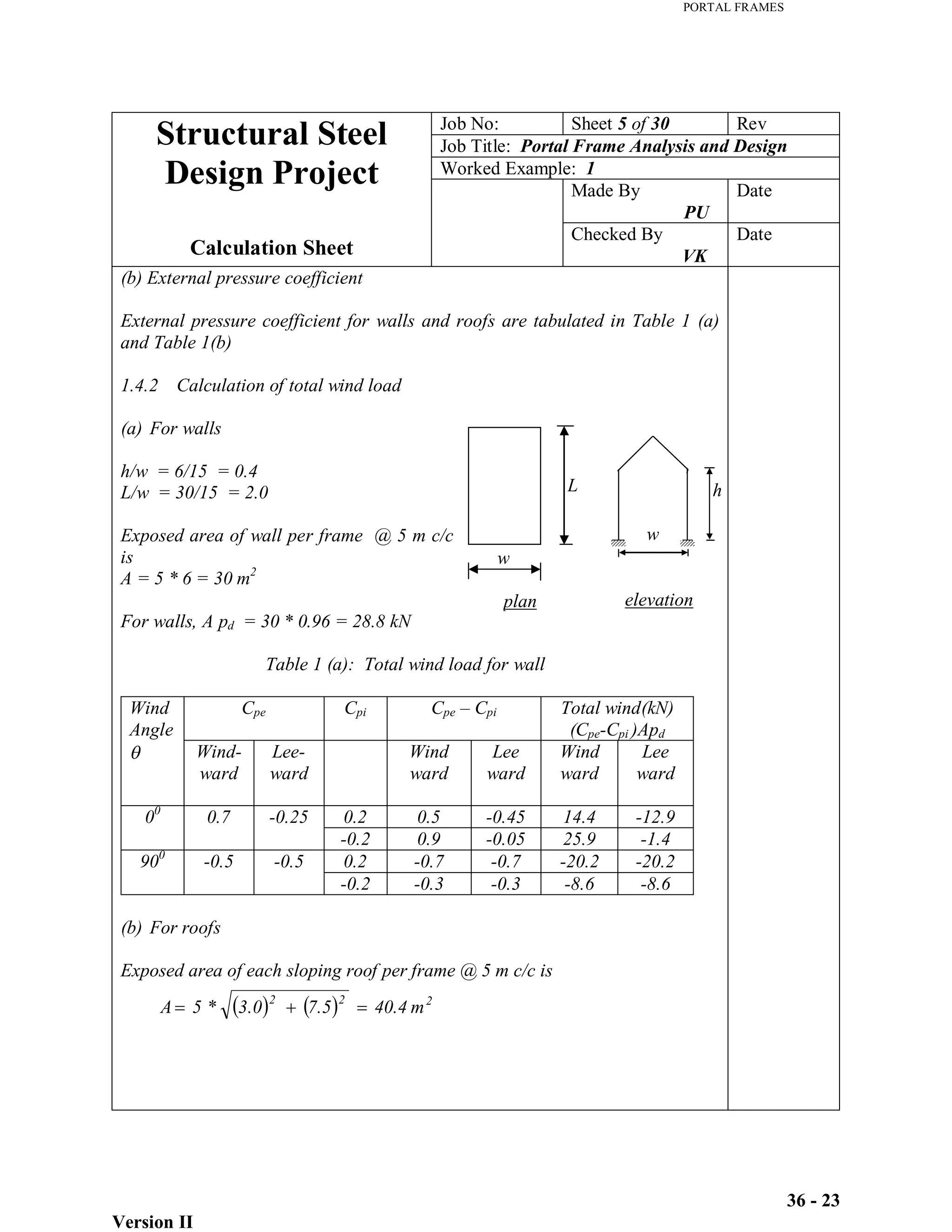
This document provides load calculations and structural analysis for a single span portal frame with a span of 15 m. It includes:
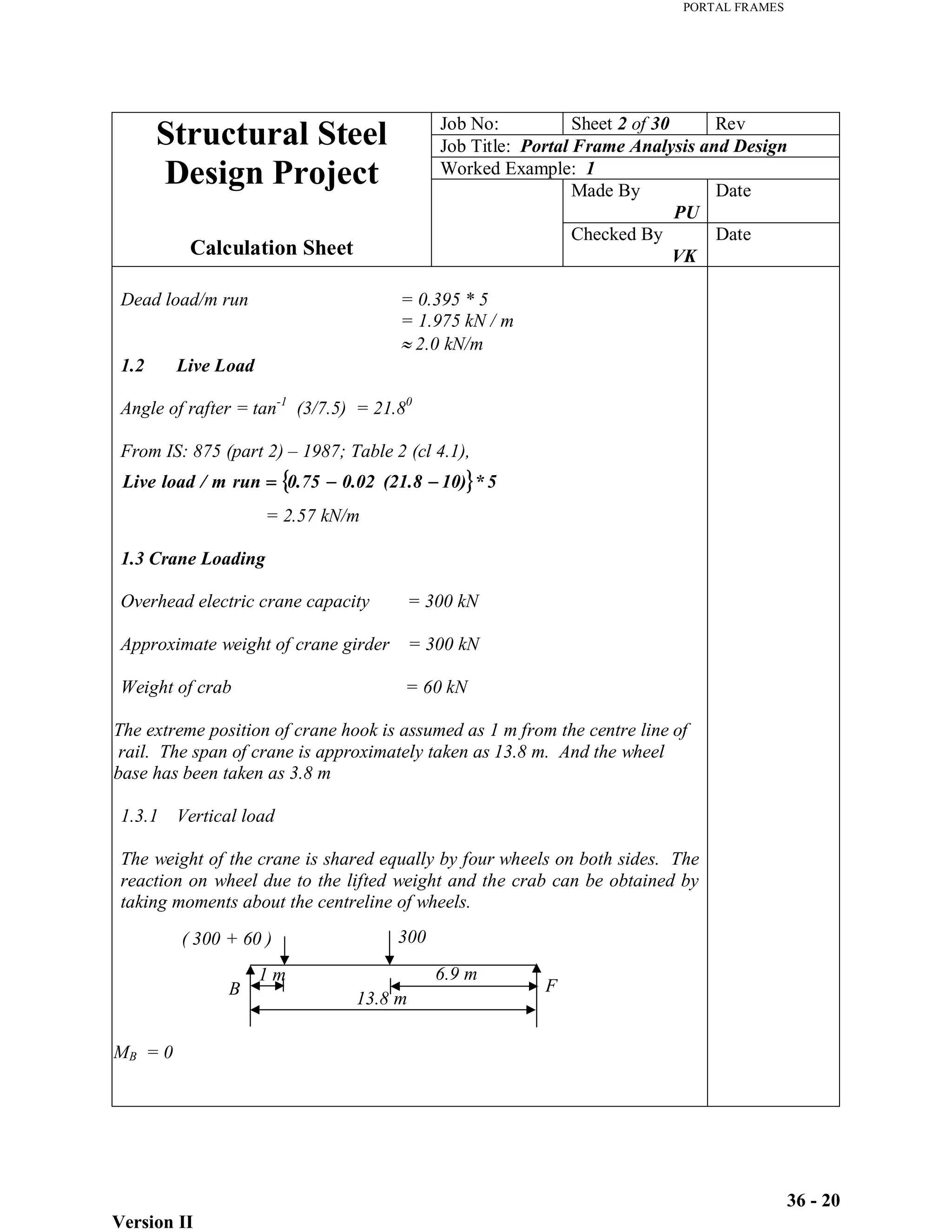
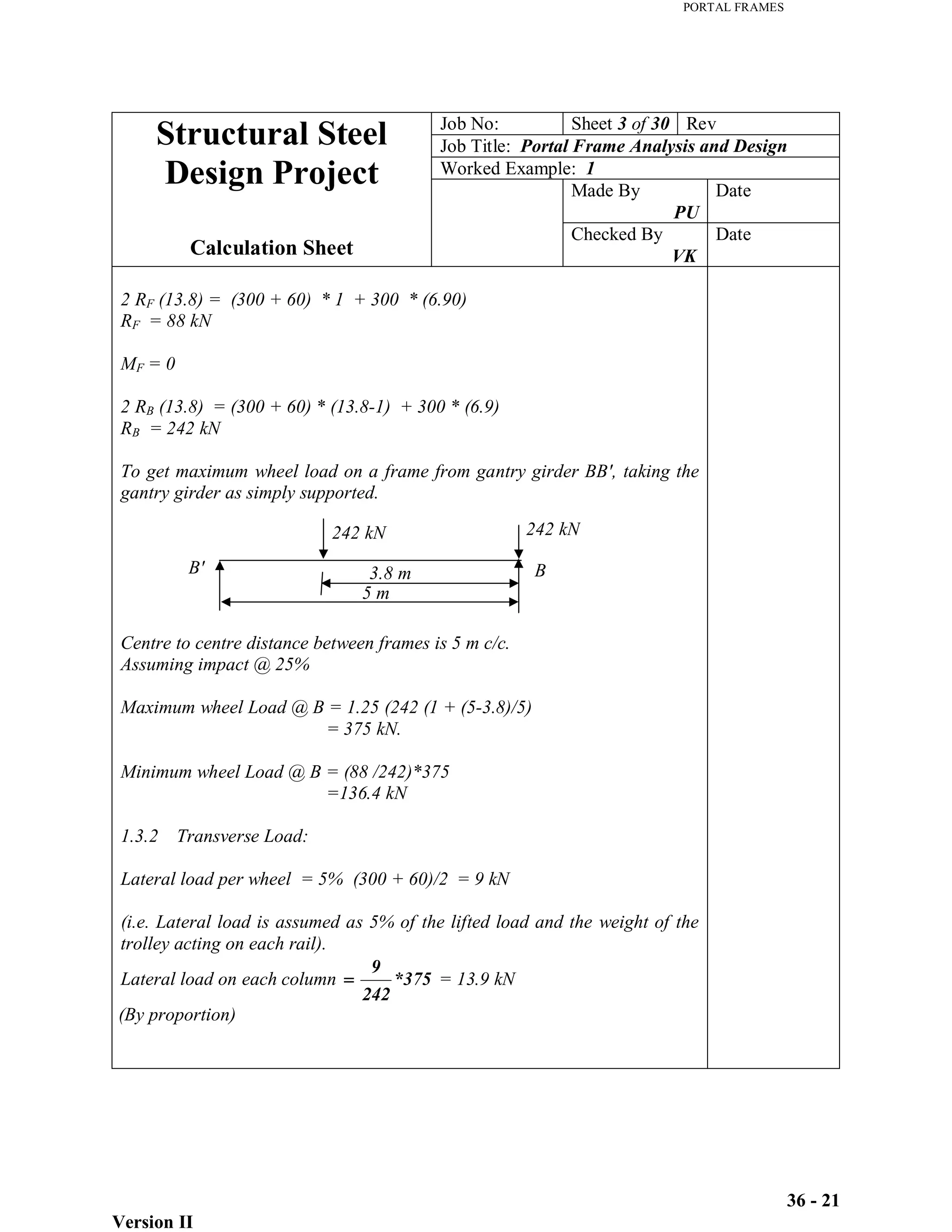
1) Calculation of dead loads, live loads, and crane loading on the frame.
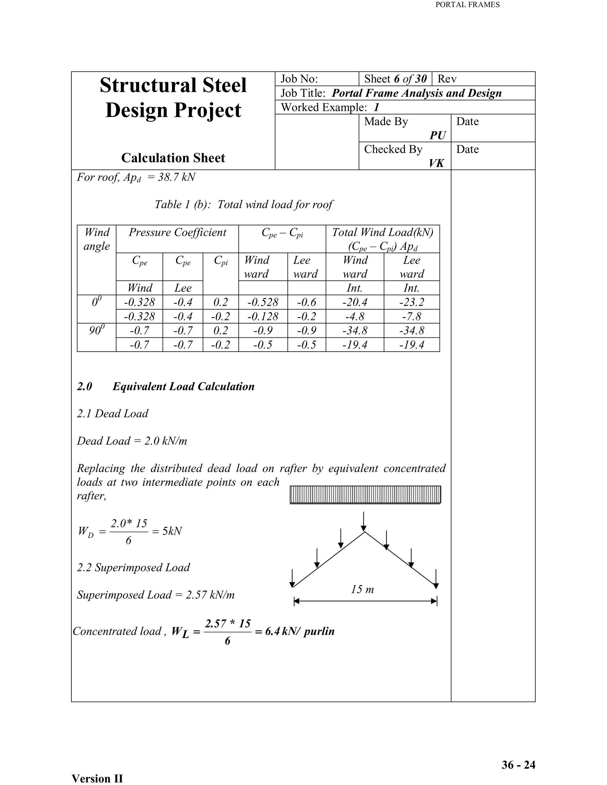
2) Equivalent load calculations to simplify distributed loads.
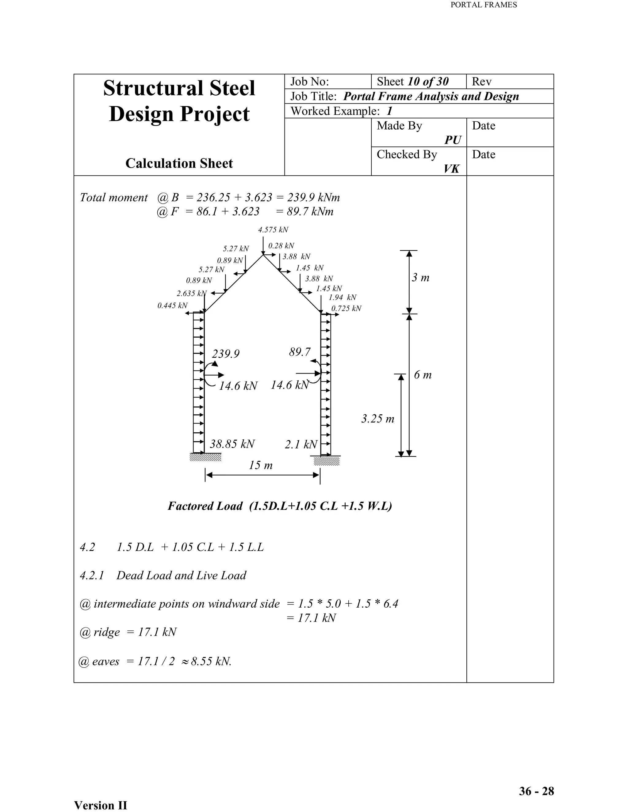
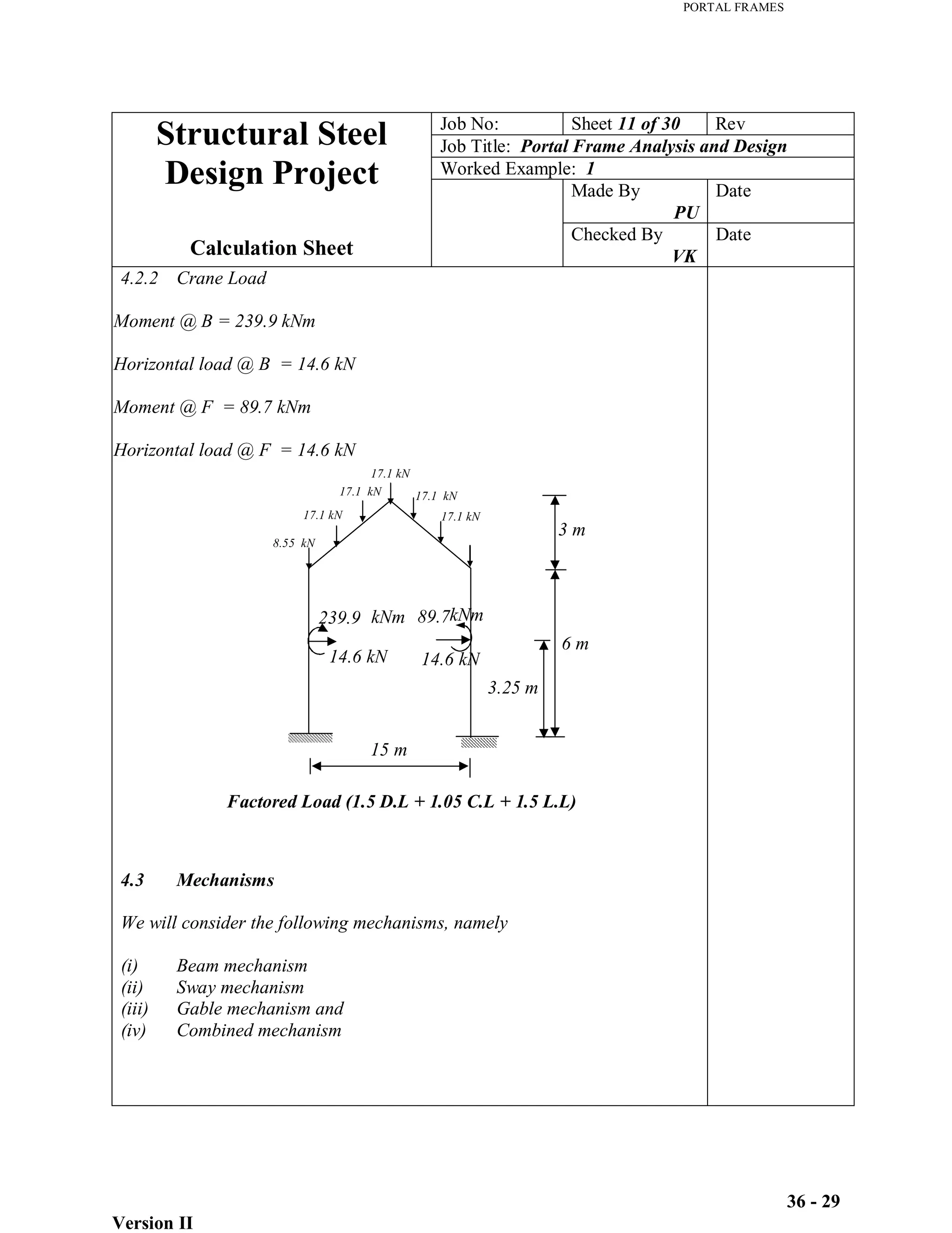
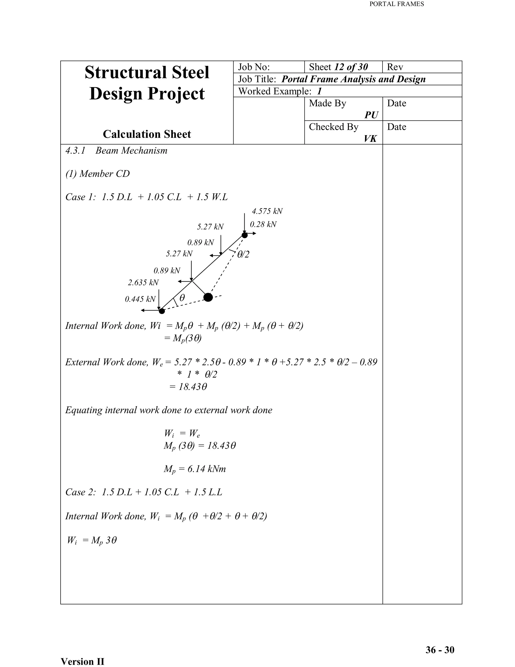
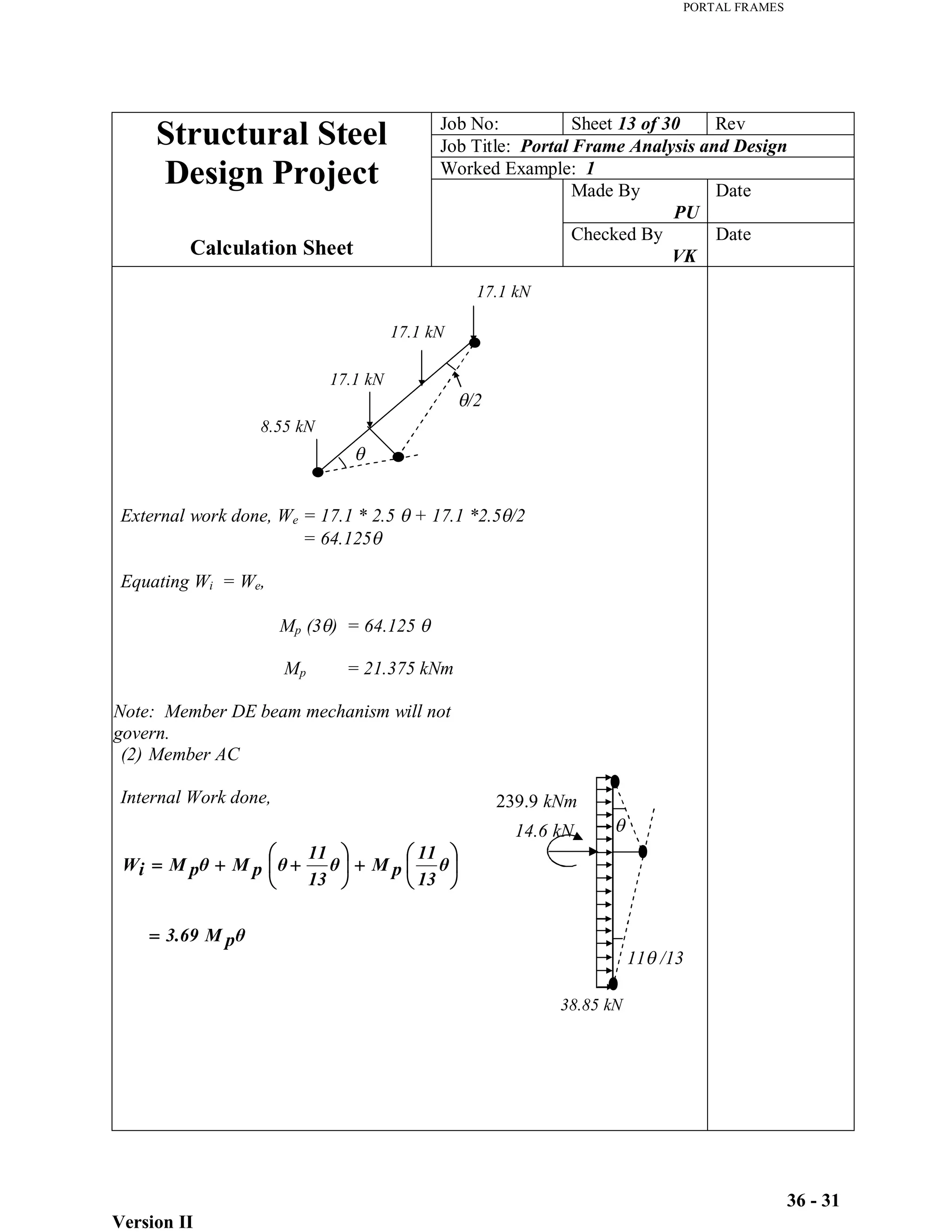
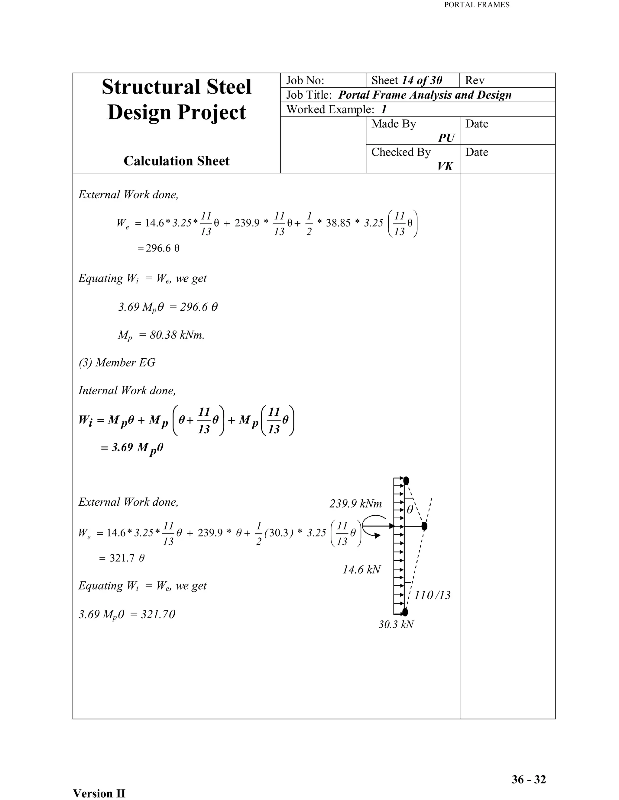
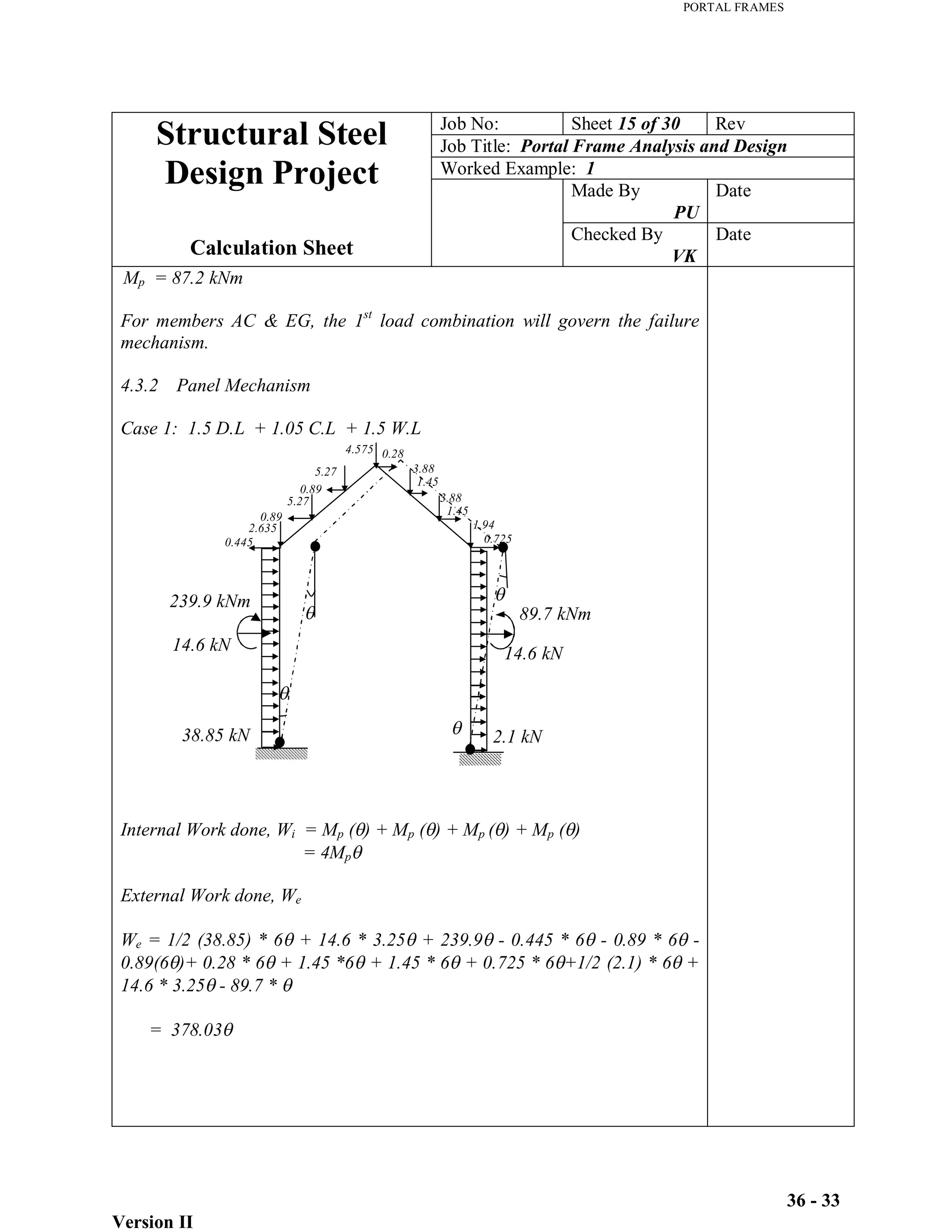
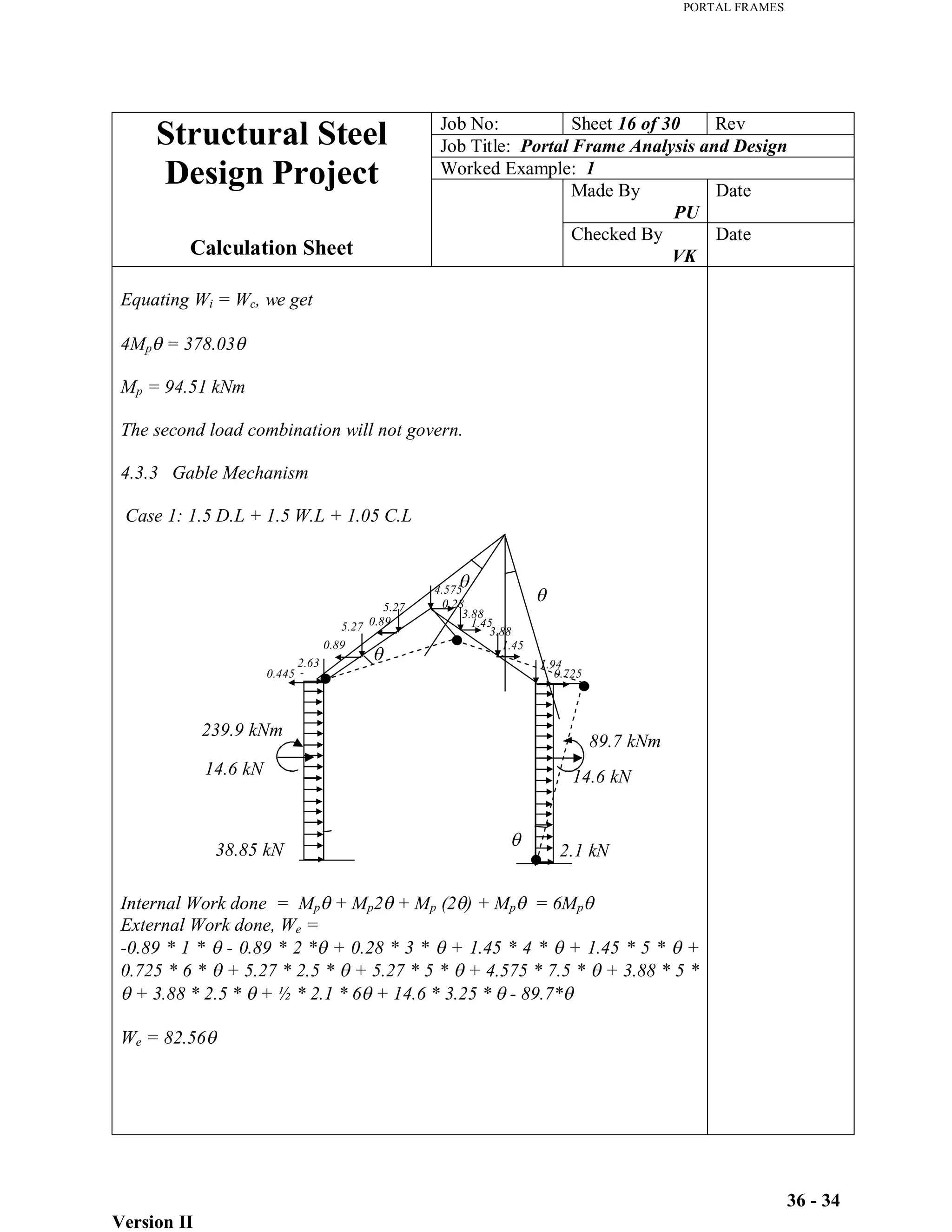
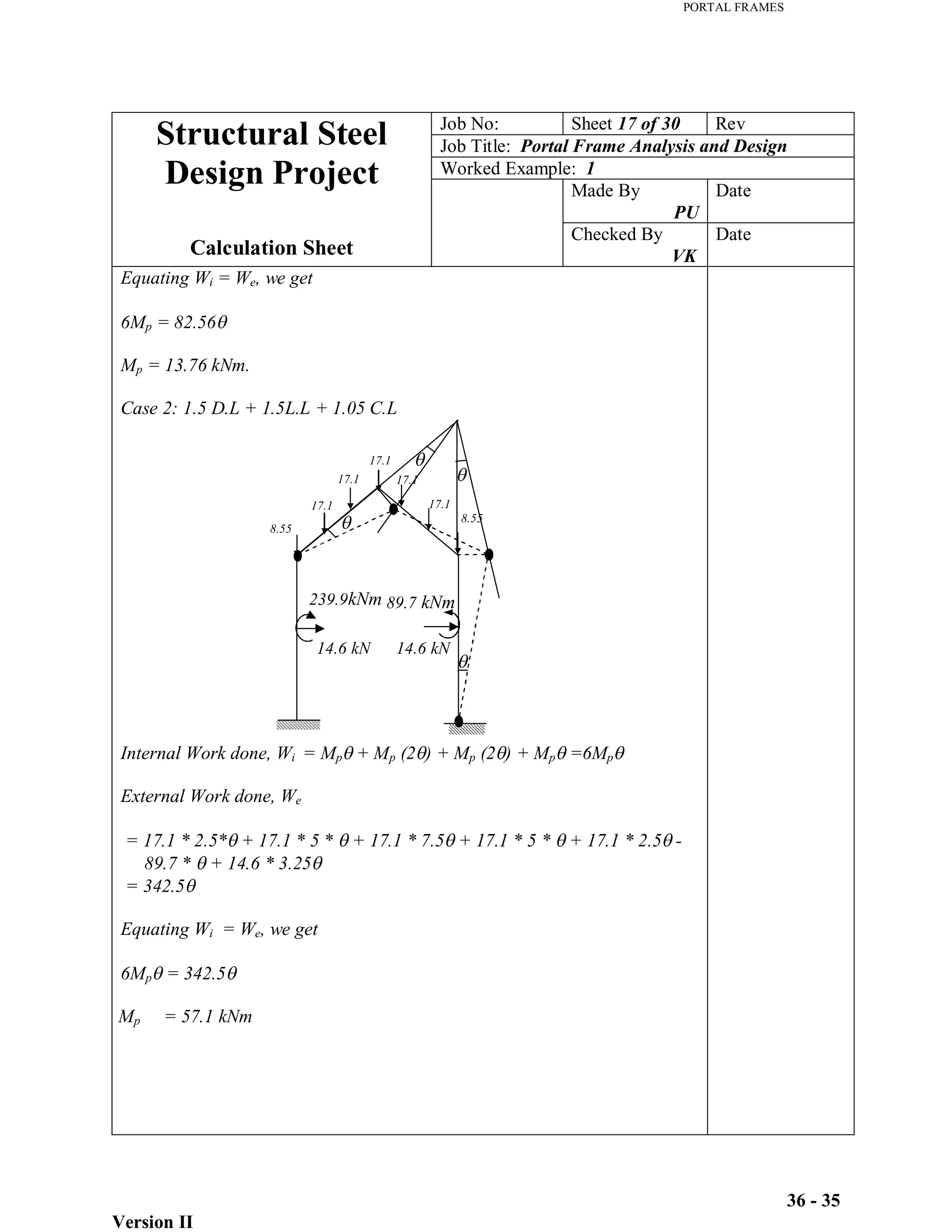
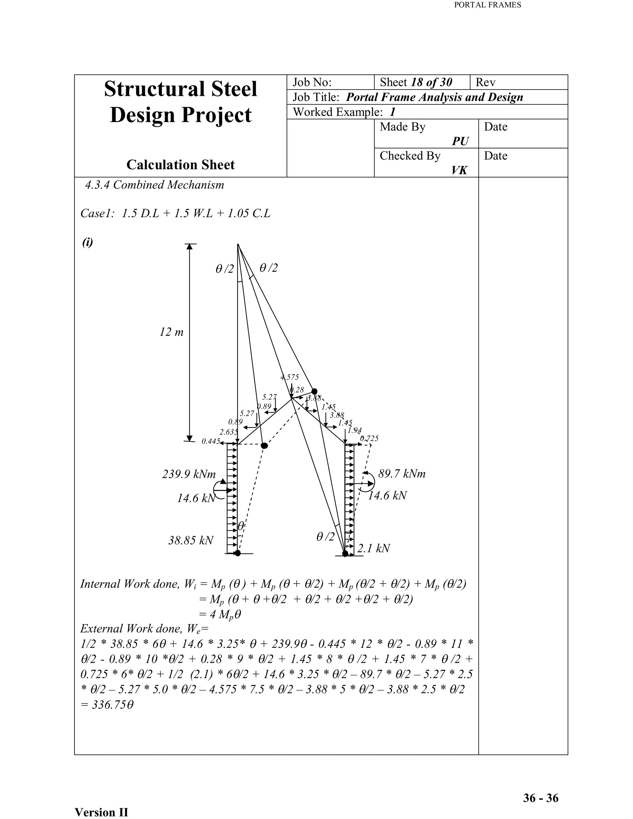
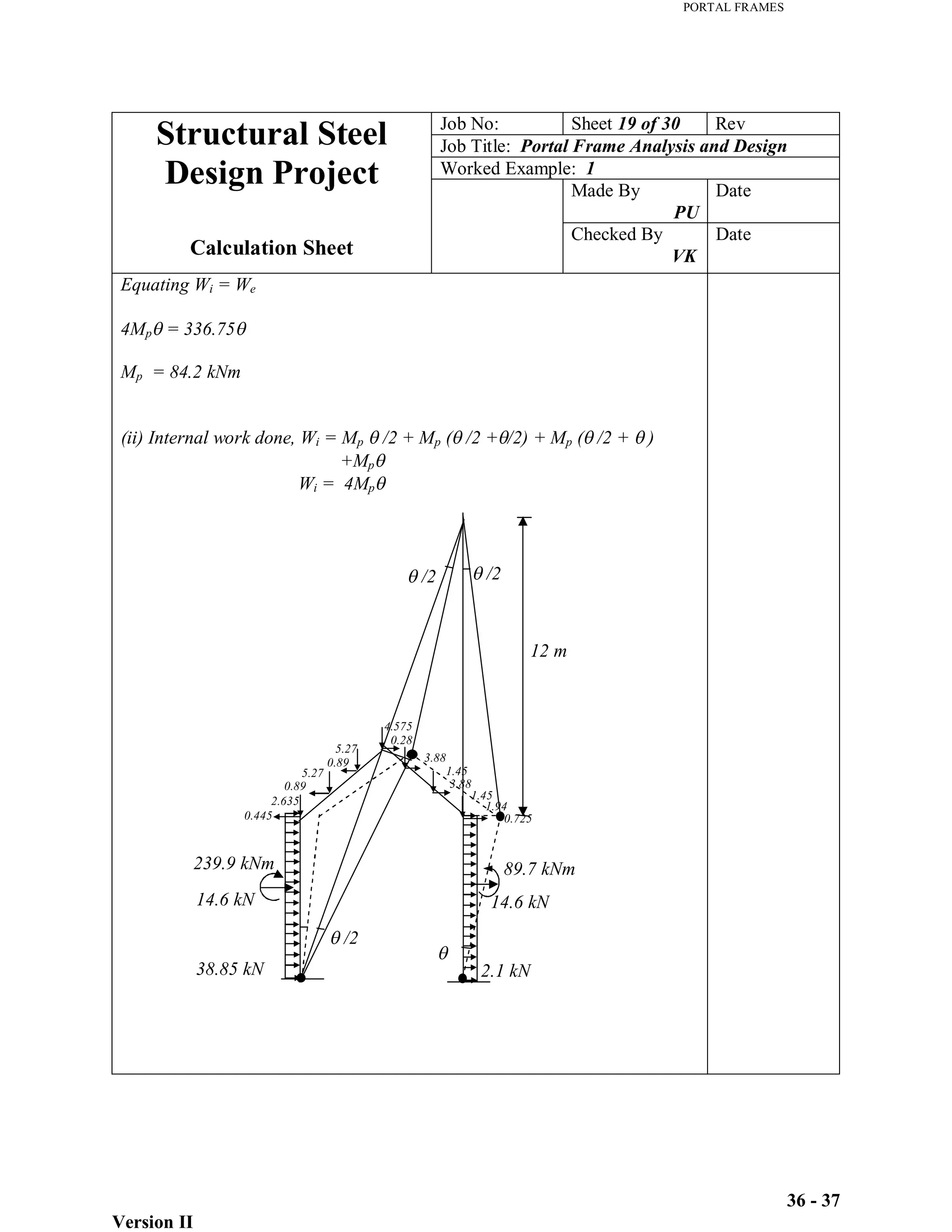
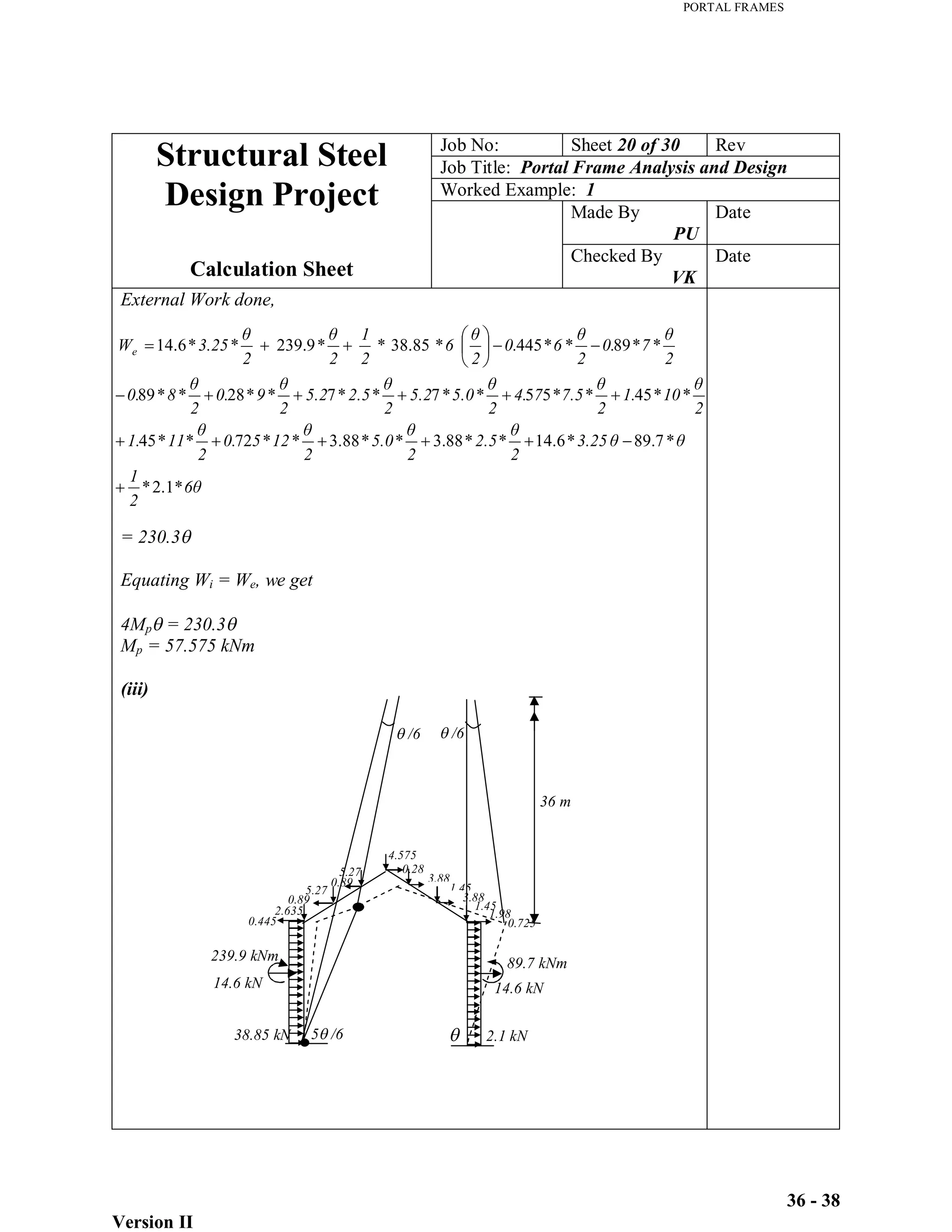
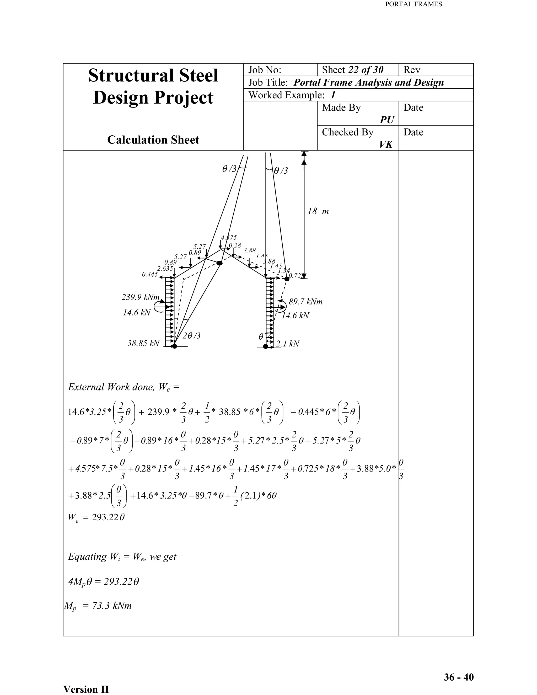
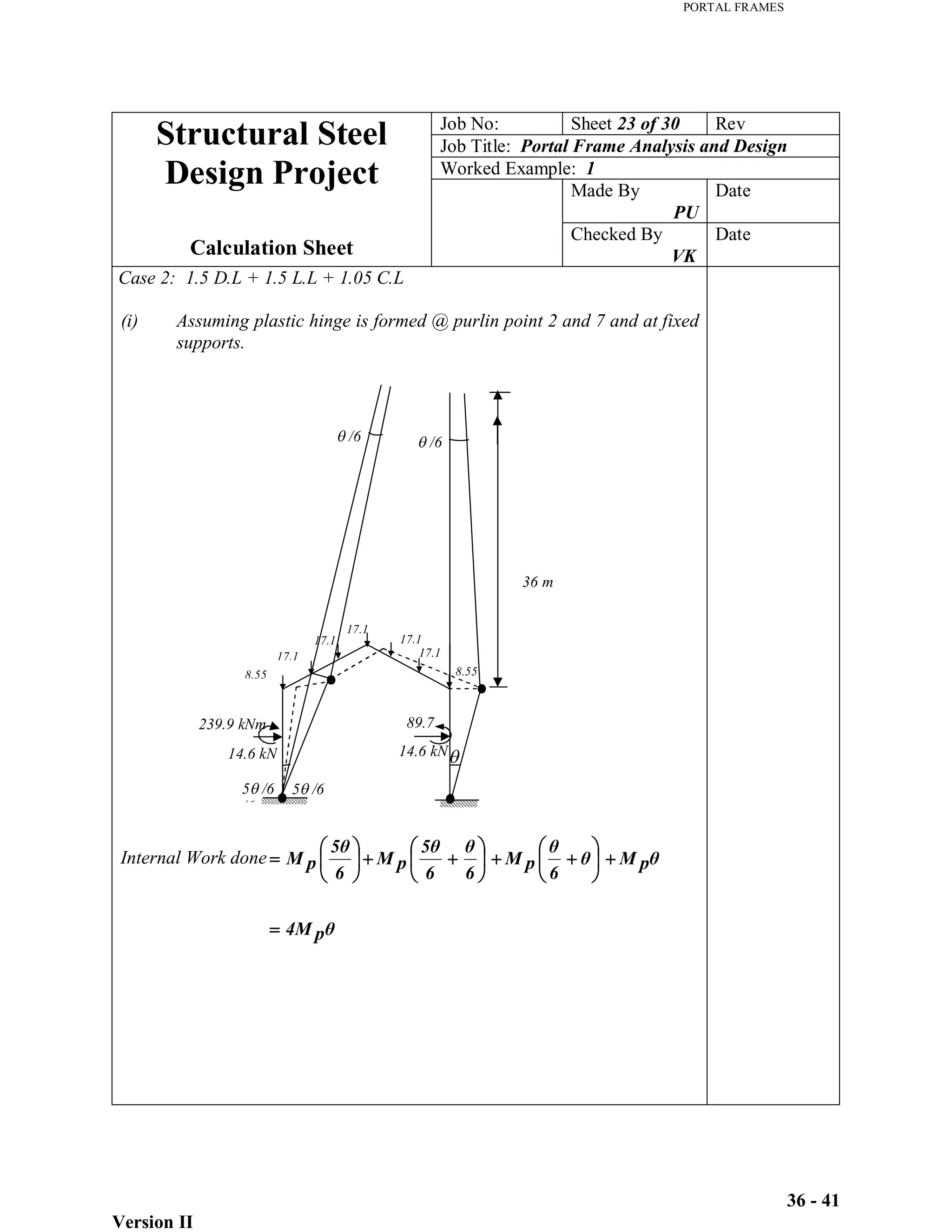
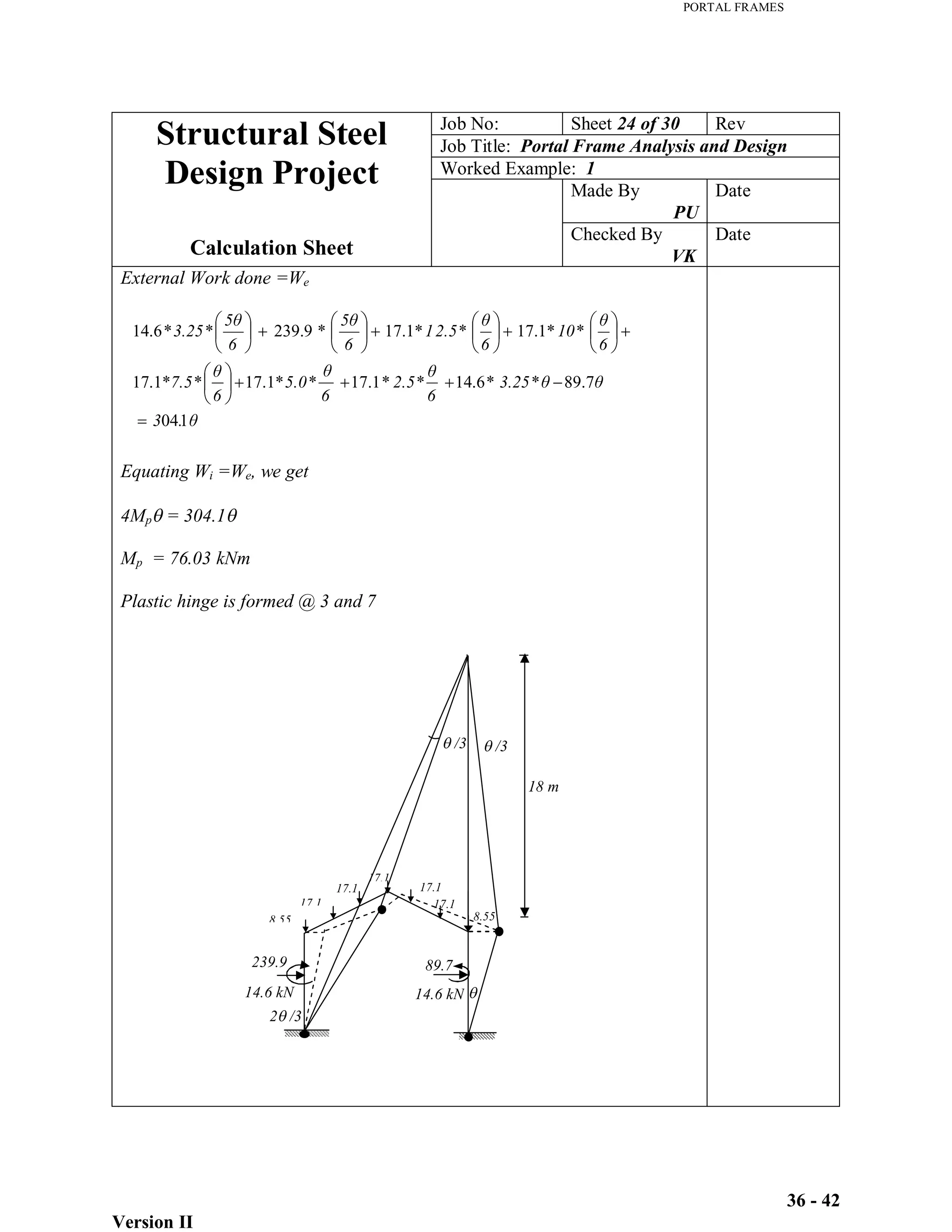
3) Analysis of the frame under different load combinations, considering beam, sway, gable, and combined mechanisms.
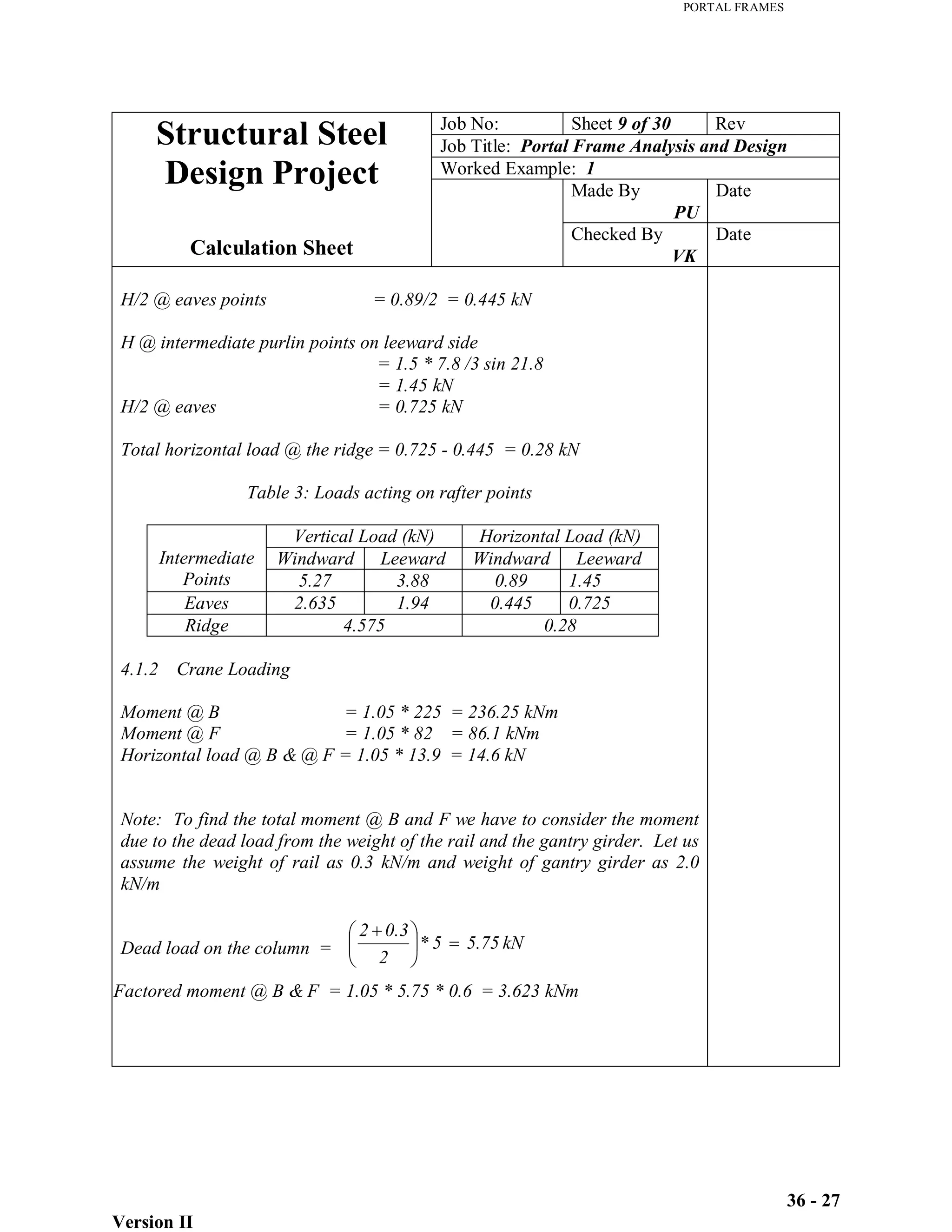
4) Tabulation of factored loads at different points on the rafters and columns.
The analysis will be used to design the sections of the frame members.