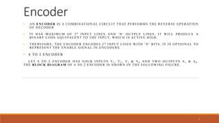
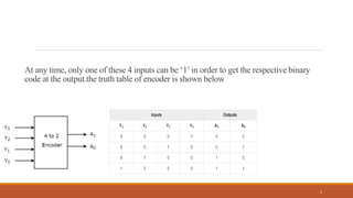
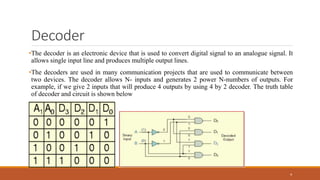
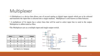
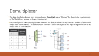
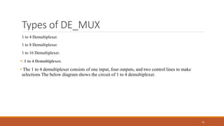
Encoder
• AN ENCODER IS A COMBINATIONAL CIRCUIT THAT PERFORMS THE REVERSE OPERATION
OF DECODER
• IT HAS MAXIMUM OF 2N INPUT LINES AND ‘N’ OUTPUT LINES. IT WILL PRODUCE A
BINARY CODE EQUIVALENT TO THE INPUT, WHICH IS ACTIVE HIGH.
• THEREFORE, THE ENCODER ENCODES 2N INPUT LINES WITH ‘N’ BITS. IT IS OPTIONAL TO
REPRESENT THE ENABLE SIGNAL IN ENCODERS .
• 4 TO 2 ENCODER
LET 4 TO 2 ENCODER HAS FOUR INPUTS Y3, Y2, Y1 & Y0 AND TWO OUTPUTS A1 & A0.
THE BLOCK DIAGRAM OF 4 TO 2 ENCODER IS SHOWN IN THE FOLLOWING FIGURE.
1
At any time, only one of these 4 inputs can be ‘1’in order to get the respective binary
code at the output.the truth table of encoder is shown below
2
Types of encoder
•There are 2 main types encoder
•1: binary encoder
•2: priority encoder
3
Decoder
•The decoder is an electronic device that is used to convert digital signal to an analogue signal. It
allows single input line and produces multiple output lines.
•The decoders are used in many communication projects that are used to communicate between
two devices. The decoder allows N- inputs and generates 2 power N-numbers of outputs. For
example, if we give 2 inputs that will produce 4 outputs by using 4 by 2 decoder. The truth table
of decoder and circuit is shown below
4
Types of Decoder
• Binary Decoders.
• 2-to-4 Binary Decoder.
• 3-to-8 Decoder.
• 4-to-16 Decoder.
• Applications of Decoders. Binary to Decimal Decoder. Address Decoders. Instruction Decoder.
5
2-to-4 line Decoder
In this type of encoders and decoders, decoders contain two inputs A0, A1, and four outputs represented by
D0, D1, D2, and D3. As you can see in the truth table – for each input combination, one output line is
activated.
6
Multiplexer
• A Multiplexer is a device that allows one of several analog or digital input signals which are to be selected
and transmits the input that is selected into a single medium. Multiplexer is also known as Data Selector.
• A multiplexer of 2n inputs has n select lines that will be used to select input line to send to the output.
Multiplexer is abbreviated as Mux.
•The Multiplexer acts as a multiple-input and single-output switch.
7
Types of Multiplexer
• The different types of multiplexing technologies are as below
• Wavelength Division Multiplexing (WDM)
• Frequency Division Multiplexing (FDM)
• Dense Wavelength Division Multiplexing (DWDM)
• Conventional Wavelength Division Multiplexing (CWDM)
• Reconfigurable Optical Add-Drop Multiplexer (ROADM)
• Orthogonal Frequency Division Multiplexing (OFDM)
• Add/Drop Multiplexing (ADM)
• Inverse Multiplexing (IMUX)
8
Demultiplexer
•The data distributor, known more commonly as a Demultiplexer or “Demux” for short, is the exact opposite
of the Multiplexer we saw in the previous tutorial.
•The demultiplexer takes one single input data line and then switches it to any one of a number of individual
output lines one at a time. The demultiplexer converts a serial data signal at the input to a parallel data at its
output lines as shown below.
9
Types of DE_MUX
1 to 4 Demultiplexer.
1 to 8 Demultiplexer.
1 to 16 Demultiplexer.
•: 1 to 4 Demultiplexer.
• The 1 to 4 demultiplexer consists of one input, four outputs, and two control lines to make
selections The below diagram shows the circuit of 1 to 4 demultiplexer.
10
What is Adder
In electronic an adder is digital circuit that perform addition of numbers. In modern computer adder reside in
the arithmetic logic unit (ALU).
It is most important device to perform numeric data operations
There are 2 types of adder
1: Half adder
2:full adder
11
Half adder
• A half adder is a type of adder, an electronic circuit that performs the addition of numbers. The half
adder is able to add two single binary digits and provide the output plus a carry value. It has two inputs,
called A and B, and two outputs S (sum) and C (carry). Half adder schemetic and truth table is shown below
12
Full adder
A full adder circuit is central to most digital circuit that perform addition or subtraction. It is so
called because it adds together two binary digits, plus a carry-in digit to produce a sum and carry-
out digit.1 It therefore has three inputs and two outputs.block diagram is shown below
NAME:MOHAMMAD SALMAN
CMS: 49060
SEMESTER: CE4TH
13
Full adder
Logical Expression for SUM:
= A’ B’ C-IN + A’ B C-IN’ + A B’ C-IN’ + A B C-IN
= C-IN (A’ B’ + A B) + C-IN’ (A’ B + A B’)
= C-IN XOR (A XOR B)
= (1,2,4,7)
Logical Expression for C-OUT:
= A’ B C-IN + A B’ C-IN + A B C-IN’ + A B C-IN
= A B + B C-IN + A C-IN
= (3,5,6,7)
14

presentation.pptx

  • 1.
    Encoder • AN ENCODERIS A COMBINATIONAL CIRCUIT THAT PERFORMS THE REVERSE OPERATION OF DECODER • IT HAS MAXIMUM OF 2N INPUT LINES AND ‘N’ OUTPUT LINES. IT WILL PRODUCE A BINARY CODE EQUIVALENT TO THE INPUT, WHICH IS ACTIVE HIGH. • THEREFORE, THE ENCODER ENCODES 2N INPUT LINES WITH ‘N’ BITS. IT IS OPTIONAL TO REPRESENT THE ENABLE SIGNAL IN ENCODERS . • 4 TO 2 ENCODER LET 4 TO 2 ENCODER HAS FOUR INPUTS Y3, Y2, Y1 & Y0 AND TWO OUTPUTS A1 & A0. THE BLOCK DIAGRAM OF 4 TO 2 ENCODER IS SHOWN IN THE FOLLOWING FIGURE. 1
  • 2.
    At any time,only one of these 4 inputs can be ‘1’in order to get the respective binary code at the output.the truth table of encoder is shown below 2
  • 3.
    Types of encoder •Thereare 2 main types encoder •1: binary encoder •2: priority encoder 3
  • 4.
    Decoder •The decoder isan electronic device that is used to convert digital signal to an analogue signal. It allows single input line and produces multiple output lines. •The decoders are used in many communication projects that are used to communicate between two devices. The decoder allows N- inputs and generates 2 power N-numbers of outputs. For example, if we give 2 inputs that will produce 4 outputs by using 4 by 2 decoder. The truth table of decoder and circuit is shown below 4
  • 5.
    Types of Decoder •Binary Decoders. • 2-to-4 Binary Decoder. • 3-to-8 Decoder. • 4-to-16 Decoder. • Applications of Decoders. Binary to Decimal Decoder. Address Decoders. Instruction Decoder. 5
  • 6.
    2-to-4 line Decoder Inthis type of encoders and decoders, decoders contain two inputs A0, A1, and four outputs represented by D0, D1, D2, and D3. As you can see in the truth table – for each input combination, one output line is activated. 6
  • 7.
    Multiplexer • A Multiplexeris a device that allows one of several analog or digital input signals which are to be selected and transmits the input that is selected into a single medium. Multiplexer is also known as Data Selector. • A multiplexer of 2n inputs has n select lines that will be used to select input line to send to the output. Multiplexer is abbreviated as Mux. •The Multiplexer acts as a multiple-input and single-output switch. 7
  • 8.
    Types of Multiplexer •The different types of multiplexing technologies are as below • Wavelength Division Multiplexing (WDM) • Frequency Division Multiplexing (FDM) • Dense Wavelength Division Multiplexing (DWDM) • Conventional Wavelength Division Multiplexing (CWDM) • Reconfigurable Optical Add-Drop Multiplexer (ROADM) • Orthogonal Frequency Division Multiplexing (OFDM) • Add/Drop Multiplexing (ADM) • Inverse Multiplexing (IMUX) 8
  • 9.
    Demultiplexer •The data distributor,known more commonly as a Demultiplexer or “Demux” for short, is the exact opposite of the Multiplexer we saw in the previous tutorial. •The demultiplexer takes one single input data line and then switches it to any one of a number of individual output lines one at a time. The demultiplexer converts a serial data signal at the input to a parallel data at its output lines as shown below. 9
  • 10.
    Types of DE_MUX 1to 4 Demultiplexer. 1 to 8 Demultiplexer. 1 to 16 Demultiplexer. •: 1 to 4 Demultiplexer. • The 1 to 4 demultiplexer consists of one input, four outputs, and two control lines to make selections The below diagram shows the circuit of 1 to 4 demultiplexer. 10
  • 11.
    What is Adder Inelectronic an adder is digital circuit that perform addition of numbers. In modern computer adder reside in the arithmetic logic unit (ALU). It is most important device to perform numeric data operations There are 2 types of adder 1: Half adder 2:full adder 11
  • 12.
    Half adder • Ahalf adder is a type of adder, an electronic circuit that performs the addition of numbers. The half adder is able to add two single binary digits and provide the output plus a carry value. It has two inputs, called A and B, and two outputs S (sum) and C (carry). Half adder schemetic and truth table is shown below 12
  • 13.
    Full adder A fulladder circuit is central to most digital circuit that perform addition or subtraction. It is so called because it adds together two binary digits, plus a carry-in digit to produce a sum and carry- out digit.1 It therefore has three inputs and two outputs.block diagram is shown below NAME:MOHAMMAD SALMAN CMS: 49060 SEMESTER: CE4TH 13
  • 14.
    Full adder Logical Expressionfor SUM: = A’ B’ C-IN + A’ B C-IN’ + A B’ C-IN’ + A B C-IN = C-IN (A’ B’ + A B) + C-IN’ (A’ B + A B’) = C-IN XOR (A XOR B) = (1,2,4,7) Logical Expression for C-OUT: = A’ B C-IN + A B’ C-IN + A B C-IN’ + A B C-IN = A B + B C-IN + A C-IN = (3,5,6,7) 14