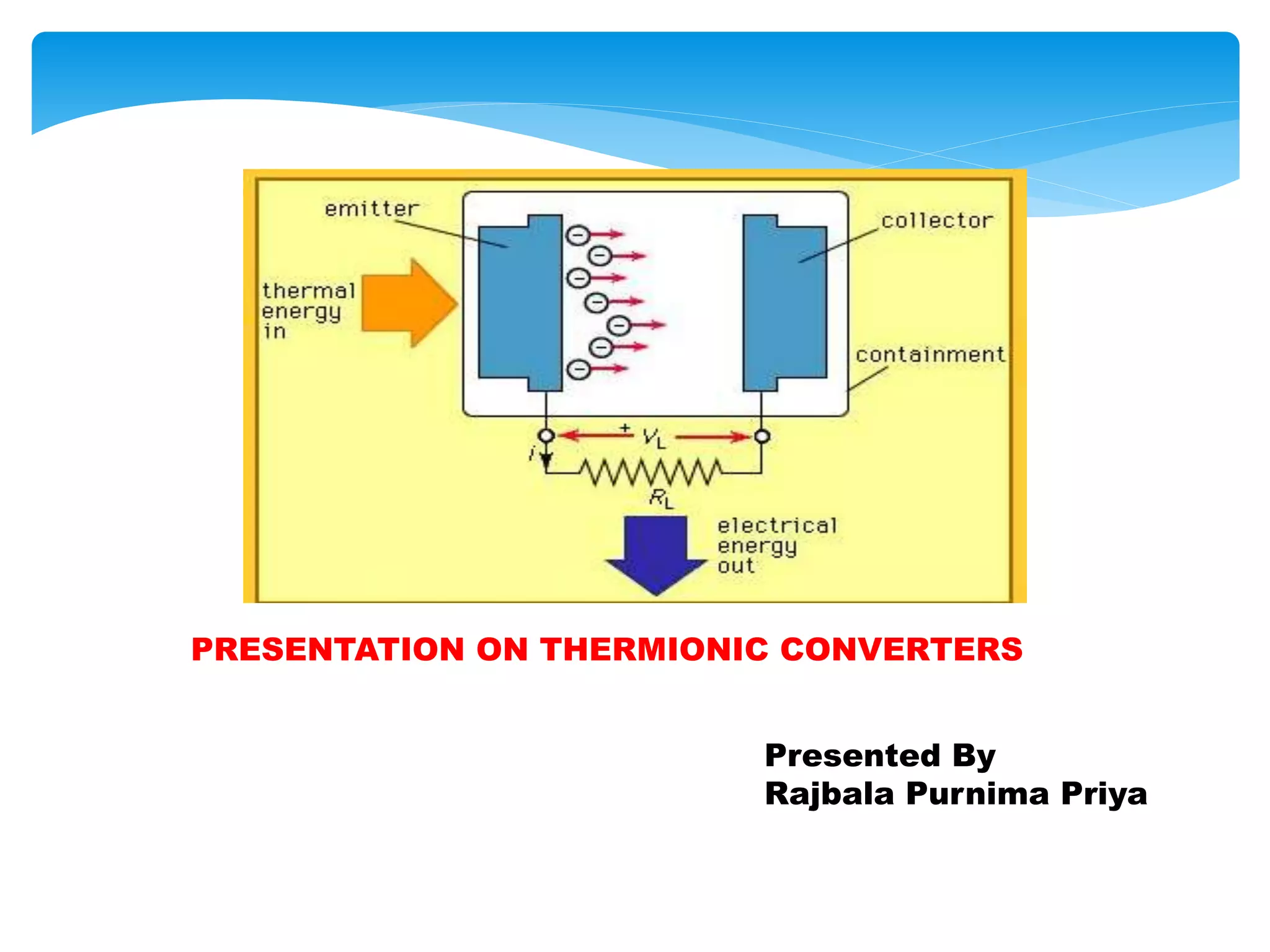
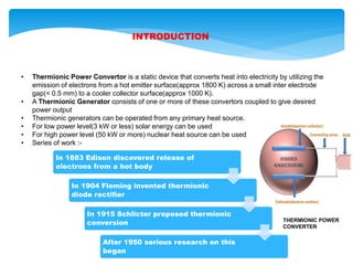
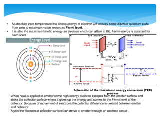
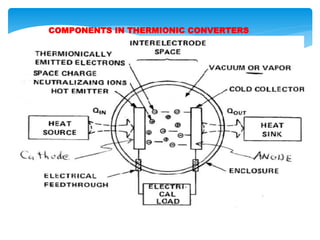
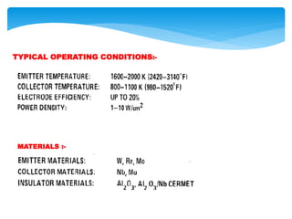
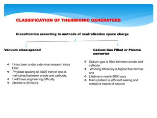
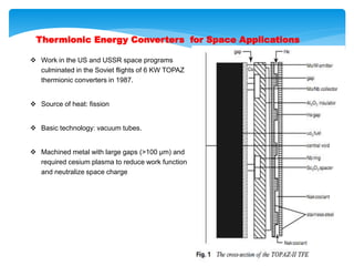
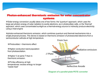
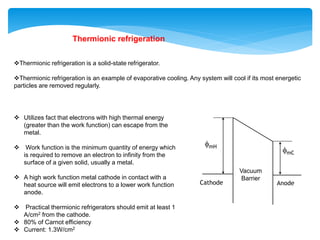
PRESENTATION ON THERMIONIC CONVERTERS
Presented By
Rajbala Purnima Priya
CONTENTS
1. INTRODUCTION
2. PRINCIPLE OF OPERATION OF THERMIONIC GENERATION
3. COMPONENTS IN THERMIONIC CONVERTERS
4. TYPICAL OPERATING CONDITIONS
5. CLASSIFICATION OF THERMIONIC GENERATERS
6. Advantages & Disadvantages of TIC
7. APPLICATIONS
8. Thermionic Energy Converters for Space Applications
9. Photon-enhanced thermionic emission for solar concentrator systems
10. Thermionic refrigeration
INTRODUCTION
• Thermionic Power Convertor is a static device that converts heat into electricity by utilizing the
emission of electrons from a hot emitter surface(approx 1800 K) across a small inter electrode
gap(< 0.5 mm) to a cooler collector surface(approx 1000 K).
• A Thermionic Generator consists of one or more of these convertors coupled to give desired
power output
• Thermionic generators can be operated from any primary heat source.
• For low power level(3 kW or less) solar energy can be used
• For high power level (50 kW or more) nuclear heat source can be used
• Series of work :-
In 1883 Edison discovered release of
electrons from a hot body
In 1904 Fleming invented thermionic
diode rectifier
In 1915 Schlicter proposed thermionic
conversion
After 1950 serious research on this
began
THERMIONIC POWER
CONVERTER
PRINCIPLE OF OPERATION OF THERMIONIC GENERATION
• Electron distribution follows FERMI-DIRAC DISTRIBUTION LAW.
• Distribution functions are nothing but the probability density functions used to describe the
probability with which a particular particle can occupy a particular energy level .
• When we speak of Fermi-Dirac distribution function, we are particularly interested in knowing the
chance by which we can find a fermion in a particular energy state of an atom.
• The Fermi function is given by the below equation:-
Where
f(E) is Probability of Occupation
k is the Boltzmann constant
T is the absolute temperature
Ef is the Fermi level or the Fermi energy
• At absolute zero temperature the kinetic energy of electron will occupy some discrete quantum state
from zero to maximum value known as Fermi level.
• It is also the maximum kinetic energy an electron which can attain at 0K. Fermi energy is constant for
each solid.
When heat is applied at emitter some high energy electron escapes from the emitter surface and
strike the collector surface where it gives up the energy and comes to the Fermi level of the
collector. Because of movement of electrons the potential difference is created between emitter
and collector.
Again the electron at collector surface can move to emitter through an external circuit .
Schematic of the thermionic energy conversion (TEC)
process
COMPONENTS IN THERMIONIC CONVERTERS
TYPICAL OPERATING CONDITIONS:-
MATERIALS :-
CLASSIFICATION OF THERMIONIC GENERATERS
Classification according to methods of neutralization space charge
Vacuum close-spaced Cesium Gas Filled or Plasma
converter
 It Has been under extensive research since
1957.
 Physical spacing of .0005 inch or less is
maintained between anode and cathode.
 It will have engineering difficulty.
 Lifetime is 40 hours.
 Cesium gas is filled between anode and
cathode
 Working efficiency is higher than former
one
 Lifetime is nearly 600 hours
 Main problem is efficient sealing and
corrosive nature of cesium
Advantages of TIC
 Rotating equipment is not employed
 Liquid-Vapour phase problems do not
exist
 Separators for fluids are not required
 Frictional losses due to bearings are not
present
Disadvantages of TIC
 Individual convertors are low voltage &
high current devices.
 A large number of convertors must be
sequentially arranged to obtain useful
voltage.
 Power losses in convertors can seriously
cut useful power output.
APPLICATIONS
 Thermionic conversion is also recently revisited for concentrated solar power applications.
 Formulation of new concepts such as thermionic–photovoltaic and thermionic–
thermoelectric combined hybrid devices are recent applications.
 Nuclear thermionic power system are used for space applications.
 Thermionic converters are also used for cooling of electronics devices.
Thermionic Energy Converters for Space Applications
 Work in the US and USSR space programs
culminated in the Soviet flights of 6 KW TOPAZ
thermionic converters in 1987.
 Source of heat: fission
 Basic technology: vacuum tubes.
 Machined metal with large gaps (>100 μm) and
required cesium plasma to reduce work function
and neutralize space charge
Photon-enhanced thermionic emission for solar concentrator
systems
Solar-energy conversion usually takes one of two forms: the 'quantum' approach, which uses the
large per-photon energy of solar radiation to excite electrons, as in photovoltaic cells, or the 'thermal'
approach, which uses concentrated sunlight as a thermal-energy source to indirectly produce electricity
using a heat engine
photon-enhanced thermionic emission, which combines quantum and thermal mechanisms into a
single physical process. The device is based on thermionic emission of photoexcited electrons from a
semiconductor cathode at high temperature.
Photovoltaic + thermionic effect
Higher conduction band population
from photoexcitation.
Higher V at same T than in
thermionic emission.
PV-like efficiency at high
temperatures: excess energy no longer
“waste heat”
Diagram of a parallel-plate PETE converter
Thermionic refrigeration
Thermionic refrigeration is a solid-state refrigerator.
Thermionic refrigeration is an example of evaporative cooling. Any system will cool if its most energetic
particles are removed regularly.
fmH
fmC
Cathode Anode
Vacuum
Barrier
 Utilizes fact that electrons with high thermal energy
(greater than the work function) can escape from the
metal.
 Work function is the minimum quantity of energy which
is required to remove an electron to infinity from the
surface of a given solid, usually a metal.
 A high work function metal cathode in contact with a
heat source will emit electrons to a lower work function
anode.
 Practical thermionic refrigerators should emit at least 1
A/cm2 from the cathode.
 80% of Carnot efficiency
 Current: 1.3W/cm2
Presentation on  thermionic converter for direct energy conversion

Presentation on thermionic converter for direct energy conversion

  • 1.
    PRESENTATION ON THERMIONICCONVERTERS Presented By Rajbala Purnima Priya
  • 2.
    CONTENTS 1. INTRODUCTION 2. PRINCIPLEOF OPERATION OF THERMIONIC GENERATION 3. COMPONENTS IN THERMIONIC CONVERTERS 4. TYPICAL OPERATING CONDITIONS 5. CLASSIFICATION OF THERMIONIC GENERATERS 6. Advantages & Disadvantages of TIC 7. APPLICATIONS 8. Thermionic Energy Converters for Space Applications 9. Photon-enhanced thermionic emission for solar concentrator systems 10. Thermionic refrigeration
  • 3.
    INTRODUCTION • Thermionic PowerConvertor is a static device that converts heat into electricity by utilizing the emission of electrons from a hot emitter surface(approx 1800 K) across a small inter electrode gap(< 0.5 mm) to a cooler collector surface(approx 1000 K). • A Thermionic Generator consists of one or more of these convertors coupled to give desired power output • Thermionic generators can be operated from any primary heat source. • For low power level(3 kW or less) solar energy can be used • For high power level (50 kW or more) nuclear heat source can be used • Series of work :- In 1883 Edison discovered release of electrons from a hot body In 1904 Fleming invented thermionic diode rectifier In 1915 Schlicter proposed thermionic conversion After 1950 serious research on this began THERMIONIC POWER CONVERTER
  • 4.
    PRINCIPLE OF OPERATIONOF THERMIONIC GENERATION • Electron distribution follows FERMI-DIRAC DISTRIBUTION LAW. • Distribution functions are nothing but the probability density functions used to describe the probability with which a particular particle can occupy a particular energy level . • When we speak of Fermi-Dirac distribution function, we are particularly interested in knowing the chance by which we can find a fermion in a particular energy state of an atom. • The Fermi function is given by the below equation:- Where f(E) is Probability of Occupation k is the Boltzmann constant T is the absolute temperature Ef is the Fermi level or the Fermi energy
  • 5.
    • At absolutezero temperature the kinetic energy of electron will occupy some discrete quantum state from zero to maximum value known as Fermi level. • It is also the maximum kinetic energy an electron which can attain at 0K. Fermi energy is constant for each solid. When heat is applied at emitter some high energy electron escapes from the emitter surface and strike the collector surface where it gives up the energy and comes to the Fermi level of the collector. Because of movement of electrons the potential difference is created between emitter and collector. Again the electron at collector surface can move to emitter through an external circuit . Schematic of the thermionic energy conversion (TEC) process
  • 6.
  • 7.
  • 8.
    CLASSIFICATION OF THERMIONICGENERATERS Classification according to methods of neutralization space charge Vacuum close-spaced Cesium Gas Filled or Plasma converter  It Has been under extensive research since 1957.  Physical spacing of .0005 inch or less is maintained between anode and cathode.  It will have engineering difficulty.  Lifetime is 40 hours.  Cesium gas is filled between anode and cathode  Working efficiency is higher than former one  Lifetime is nearly 600 hours  Main problem is efficient sealing and corrosive nature of cesium
  • 9.
    Advantages of TIC Rotating equipment is not employed  Liquid-Vapour phase problems do not exist  Separators for fluids are not required  Frictional losses due to bearings are not present Disadvantages of TIC  Individual convertors are low voltage & high current devices.  A large number of convertors must be sequentially arranged to obtain useful voltage.  Power losses in convertors can seriously cut useful power output. APPLICATIONS  Thermionic conversion is also recently revisited for concentrated solar power applications.  Formulation of new concepts such as thermionic–photovoltaic and thermionic– thermoelectric combined hybrid devices are recent applications.  Nuclear thermionic power system are used for space applications.  Thermionic converters are also used for cooling of electronics devices.
  • 10.
    Thermionic Energy Convertersfor Space Applications  Work in the US and USSR space programs culminated in the Soviet flights of 6 KW TOPAZ thermionic converters in 1987.  Source of heat: fission  Basic technology: vacuum tubes.  Machined metal with large gaps (>100 μm) and required cesium plasma to reduce work function and neutralize space charge
  • 11.
    Photon-enhanced thermionic emissionfor solar concentrator systems Solar-energy conversion usually takes one of two forms: the 'quantum' approach, which uses the large per-photon energy of solar radiation to excite electrons, as in photovoltaic cells, or the 'thermal' approach, which uses concentrated sunlight as a thermal-energy source to indirectly produce electricity using a heat engine photon-enhanced thermionic emission, which combines quantum and thermal mechanisms into a single physical process. The device is based on thermionic emission of photoexcited electrons from a semiconductor cathode at high temperature. Photovoltaic + thermionic effect Higher conduction band population from photoexcitation. Higher V at same T than in thermionic emission. PV-like efficiency at high temperatures: excess energy no longer “waste heat” Diagram of a parallel-plate PETE converter
  • 12.
    Thermionic refrigeration Thermionic refrigerationis a solid-state refrigerator. Thermionic refrigeration is an example of evaporative cooling. Any system will cool if its most energetic particles are removed regularly. fmH fmC Cathode Anode Vacuum Barrier  Utilizes fact that electrons with high thermal energy (greater than the work function) can escape from the metal.  Work function is the minimum quantity of energy which is required to remove an electron to infinity from the surface of a given solid, usually a metal.  A high work function metal cathode in contact with a heat source will emit electrons to a lower work function anode.  Practical thermionic refrigerators should emit at least 1 A/cm2 from the cathode.  80% of Carnot efficiency  Current: 1.3W/cm2