Download to read offline
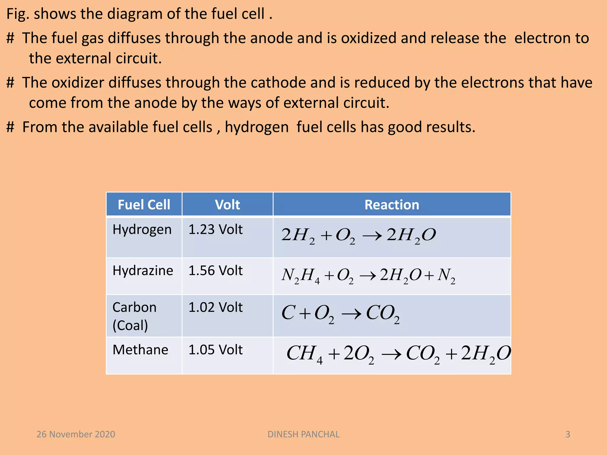
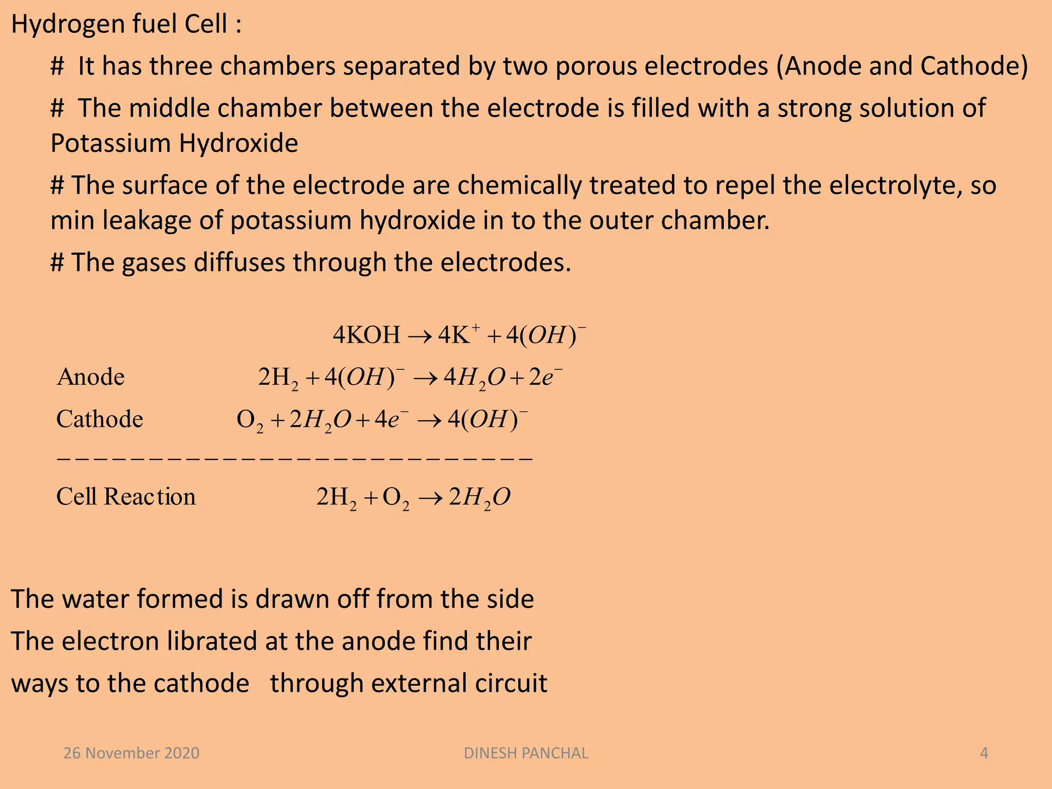
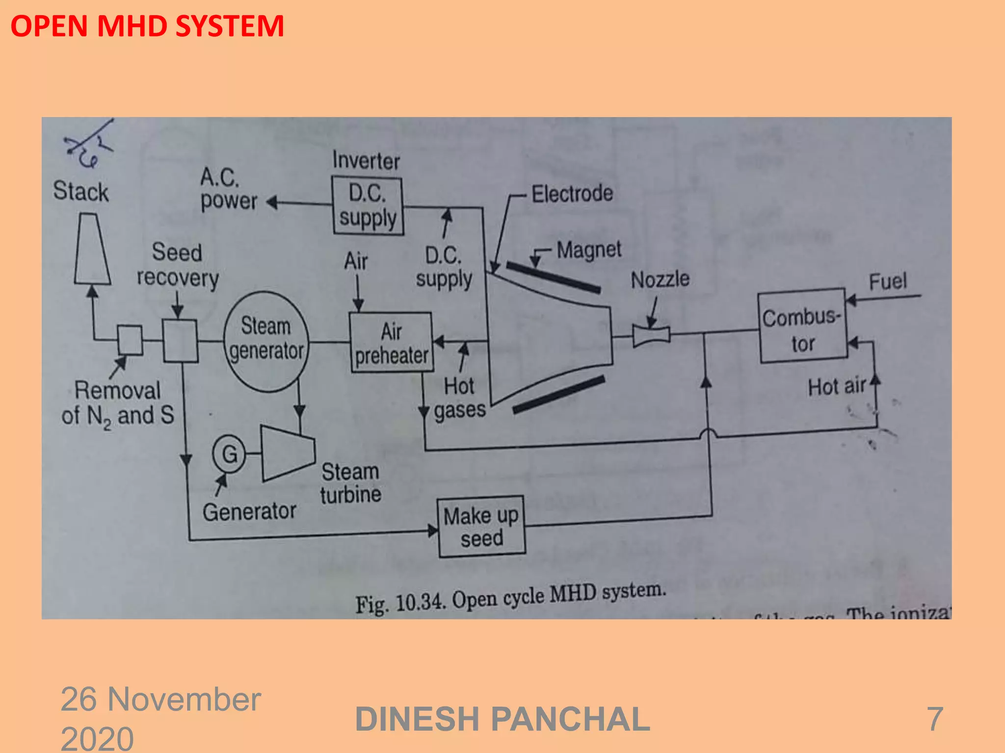
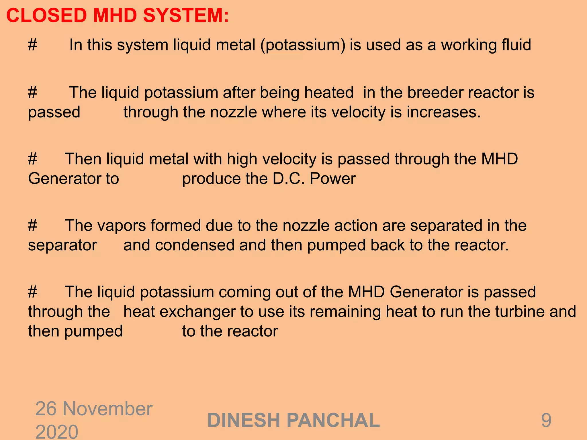
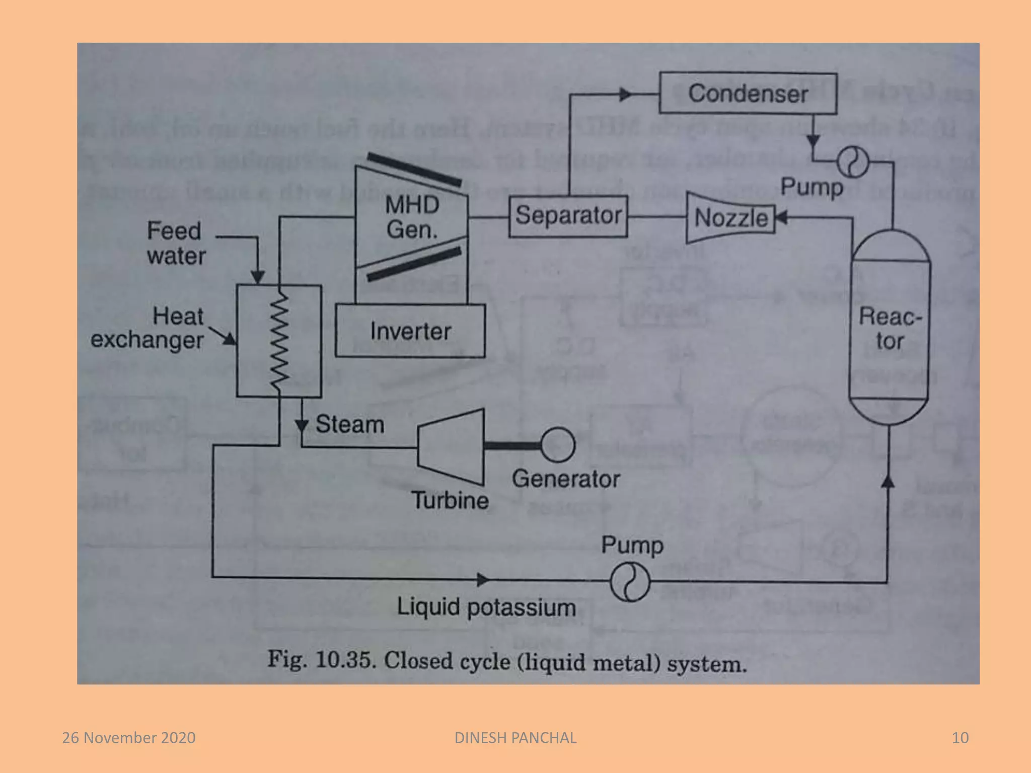
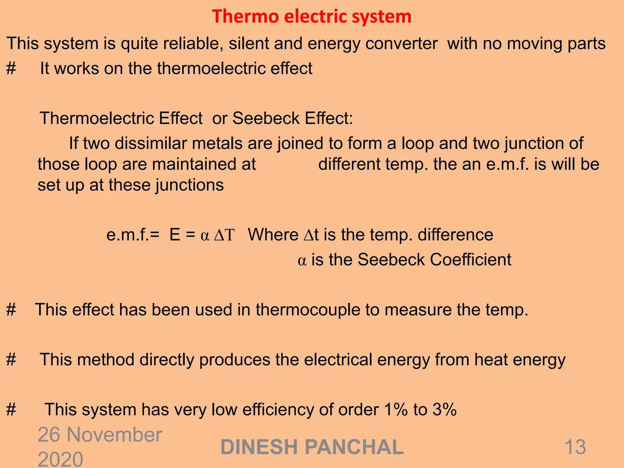
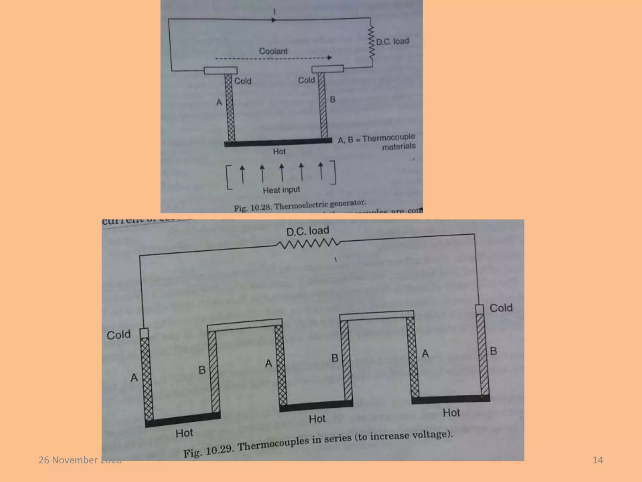

This document discusses several direct energy conversion systems, including fuel cells, magnetohydrodynamic (MHD) systems, thermoelectric systems, and thermionic power generation. Fuel cells directly convert the chemical energy of fuels like hydrogen into electricity. MHD systems use magnets and high temperature gases or liquids to directly generate electricity from heat. Thermoelectric systems use the temperature difference between hot and cold junctions of dissimilar metals to create an electric current. Thermionic power generation uses thermionic emission to extract electrons from hot metals and generate electricity.


![Gas turbine-power-plant[1]](https://cdn.slidesharecdn.com/ss_thumbnails/gas-turbine-power-plant1-150515182411-lva1-app6892-thumbnail.jpg?width=640&height=640&fit=bounds)


