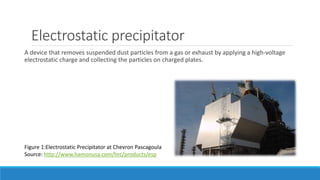
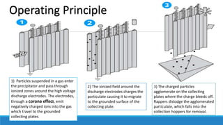
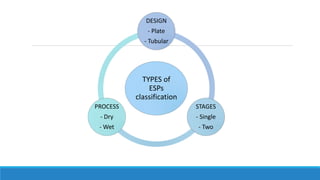
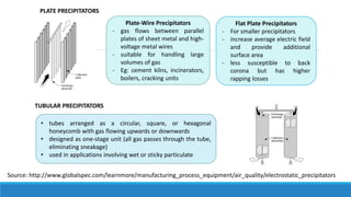
Electrostatic Precipitator
Electrostatic precipitator
A device that removes suspended dust particles from a gas or exhaust by applying a high-voltage
electrostatic charge and collecting the particles on charged plates.
Figure 1:Electrostatic Precipitator at Chevron Pascagoula
Source: http://www.hamonusa.com/hrc/products/esp
Operating Principle
3) The charged particles
agglomerate on the collecting
plates where the charge bleeds off.
Rappers dislodge the agglomerated
particulate, which falls into the
collection hoppers for removal.
1) Particles suspended in a gas enter
the precipitator and pass through
ionized zones around the high voltage
discharge electrodes. The electrodes,
through a corona effect, emit
negatively charged ions into the gas
which travel to the grounded
collecting plates.
2) The ionized field around the
discharge electrodes charges the
particulate causing it to migrate
to the grounded surface of the
collecting plate.
Equation Designing used or ESPs
Cunningham correction factor
C= 1 +
2𝜆
𝑑
.(A1 + A2 .𝑒
−𝐴3.𝑑
𝜆 )
C is the correction factor
λ is the mean free path
d is the particle diameter
An are experimentally determined coefficients.
For air (Davies, 1945):
A1 = 1.257
A2 = 0.400
A3 = 0.55
Calculate the drift speed using the Cunningham Correction
Factor
Drift Speed
𝐷𝑟𝑖𝑓𝑡 𝑠𝑝𝑒𝑒𝑑 =𝑤𝑒=
𝐶𝑞𝐸
3𝜋𝜇𝑓𝑑𝑝
q = charge acquired by each particle
E = electrical field = voltage difference divided by
electrode-plate distance d
C = Cunningham slip factor (to be obtained from
formula
𝜇𝑓= fluid viscosity = 1.81 x 10⁻⁵ kg/m.s for air at
ambient temperature
𝑑𝑝 = particle diameter
Calculate the Efficiency of ESPs
Other Equations for Overall Collection Efficiency of
ESPs
𝜂 = 1 − exp(−
𝑤𝑒𝑊𝐿
𝑄
) = 1 − exp(−
𝑤𝑒𝐴
𝑄
)
where
A=WL is the collecting plate area.
𝜂 =
𝐴𝑚𝑜𝑢𝑛𝑡 𝑟𝑒𝑚𝑜𝑣𝑒𝑑
𝐴𝑚𝑜𝑢𝑛𝑡 𝑒𝑛𝑡𝑒𝑟𝑖𝑛𝑔
=
𝐶𝑖𝑛−𝐶𝑜𝑢𝑡
𝐶𝑖𝑛
=1−
𝐶𝑜𝑢𝑡
𝐶𝑖𝑛
= 1 − exp(−
𝑤𝑒𝐿
𝑈𝑑
)
𝐹𝑙𝑜𝑤 𝑠𝑝𝑒𝑒𝑑 = 𝑈 = 𝑄/𝑊𝑑
Source: http://engineering.dartmouth.edu/~d30345d/courses/engs3
7/esps.pdf
Source: http://www.scielo.br/scielo.php?script=sci_arttext&pid=S0104-
66322001000300010
TYPES of
ESPs
classification
DESIGN
- Plate
- Tubular
STAGES
- Single
- Two
PROCESS
- Dry
- Wet
Plate-Wire Precipitators
- gas flows between parallel
plates of sheet metal and high-
voltage metal wires
- suitable for handling large
volumes of gas
- Eg: cement kilns, incinerators,
boilers, cracking units
Flat Plate Precipitators
- For smaller precipitators
- increase average electric field
and provide additional
surface area
- less susceptible to back
corona but has higher
rapping losses
PLATE PRECIPITATORS
TUBULAR PRECIPITATORS
• tubes arranged as a circular, square, or hexagonal
honeycomb with gas flowing upwards or downwards
• designed as one-stage unit (all gas passes through the tube,
eliminating sneakage)
• used in applications involving wet or sticky particulate
Source: http://www.globalspec.com/learnmore/manufacturing_process_equipment/air_quality/electrostatic_precipitators
Single stage
use very high voltages to charge
particles
operate in parallel
incorporate charging and collection
together in the same stage
Two stage
operate in series
separate particle charging and
collection stages
more time for particle charging, less
susceptibility to back corona, and
economical construction for smaller
sizes
applied to submicron sources emitting
oil mists, smokes, fumes,
or other liquid aerosols
Dry ESPs Wet ESPs
 capture particles in dry product
streams
 strip wet (saturated) gas streams of
particles
 use periodic rapping to separate the
accumulated dust
 use water sprays to condition/trap
particles for collection
 not suitable for submicron particulate
applications due to particle size,
resistivity
 can remove very fine (submicron)
particulate that dry ESPs cannot
capture
Disadvantage:
- rapping will project some of these
particles (10-15 %) back into the gas
stream (known as reentrainment)
Disadvantages:
- costly because they incorporate water
and corrosive gases
- Particulate matter is collected as a
slurry instead of a dry solid (expensive
to handle and dispose)
USAGEEXAMPLES
Used in the desalination of crude oil by using a desalter.
- Desalination is necessary to avoid corrosion from acids formed by salts in downstream oil
refinement equipment.
The picture shown below is of a refinery boiler that has a wet electrostatic precipitator installed
for treatment of flue gas emissions.
Source: PPC Air Pollution Control,
Longview, TX
Used in a variety of industries for emission reduction of particles to control air pollution.
Two examples of precipitators used in particle emission reduction:
- dry electrostatic precipitator used in boiling and drying processes
Source: PPC Air Pollution Control, Longview, TX
- wet electrostatic precipitator used to treat fryer vent exhaust in the food processing industry.
Source: PPC Air Pollution Control, Longview, TX

Electrostatic_Precipitator.pptx

  • 1.
  • 2.
    Electrostatic precipitator A devicethat removes suspended dust particles from a gas or exhaust by applying a high-voltage electrostatic charge and collecting the particles on charged plates. Figure 1:Electrostatic Precipitator at Chevron Pascagoula Source: http://www.hamonusa.com/hrc/products/esp
  • 3.
    Operating Principle 3) Thecharged particles agglomerate on the collecting plates where the charge bleeds off. Rappers dislodge the agglomerated particulate, which falls into the collection hoppers for removal. 1) Particles suspended in a gas enter the precipitator and pass through ionized zones around the high voltage discharge electrodes. The electrodes, through a corona effect, emit negatively charged ions into the gas which travel to the grounded collecting plates. 2) The ionized field around the discharge electrodes charges the particulate causing it to migrate to the grounded surface of the collecting plate.
  • 4.
    Equation Designing usedor ESPs Cunningham correction factor C= 1 + 2𝜆 𝑑 .(A1 + A2 .𝑒 −𝐴3.𝑑 𝜆 ) C is the correction factor λ is the mean free path d is the particle diameter An are experimentally determined coefficients. For air (Davies, 1945): A1 = 1.257 A2 = 0.400 A3 = 0.55 Calculate the drift speed using the Cunningham Correction Factor Drift Speed 𝐷𝑟𝑖𝑓𝑡 𝑠𝑝𝑒𝑒𝑑 =𝑤𝑒= 𝐶𝑞𝐸 3𝜋𝜇𝑓𝑑𝑝 q = charge acquired by each particle E = electrical field = voltage difference divided by electrode-plate distance d C = Cunningham slip factor (to be obtained from formula 𝜇𝑓= fluid viscosity = 1.81 x 10⁻⁵ kg/m.s for air at ambient temperature 𝑑𝑝 = particle diameter
  • 5.
    Calculate the Efficiencyof ESPs Other Equations for Overall Collection Efficiency of ESPs 𝜂 = 1 − exp(− 𝑤𝑒𝑊𝐿 𝑄 ) = 1 − exp(− 𝑤𝑒𝐴 𝑄 ) where A=WL is the collecting plate area. 𝜂 = 𝐴𝑚𝑜𝑢𝑛𝑡 𝑟𝑒𝑚𝑜𝑣𝑒𝑑 𝐴𝑚𝑜𝑢𝑛𝑡 𝑒𝑛𝑡𝑒𝑟𝑖𝑛𝑔 = 𝐶𝑖𝑛−𝐶𝑜𝑢𝑡 𝐶𝑖𝑛 =1− 𝐶𝑜𝑢𝑡 𝐶𝑖𝑛 = 1 − exp(− 𝑤𝑒𝐿 𝑈𝑑 ) 𝐹𝑙𝑜𝑤 𝑠𝑝𝑒𝑒𝑑 = 𝑈 = 𝑄/𝑊𝑑 Source: http://engineering.dartmouth.edu/~d30345d/courses/engs3 7/esps.pdf Source: http://www.scielo.br/scielo.php?script=sci_arttext&pid=S0104- 66322001000300010
  • 6.
    TYPES of ESPs classification DESIGN - Plate -Tubular STAGES - Single - Two PROCESS - Dry - Wet
  • 7.
    Plate-Wire Precipitators - gasflows between parallel plates of sheet metal and high- voltage metal wires - suitable for handling large volumes of gas - Eg: cement kilns, incinerators, boilers, cracking units Flat Plate Precipitators - For smaller precipitators - increase average electric field and provide additional surface area - less susceptible to back corona but has higher rapping losses PLATE PRECIPITATORS TUBULAR PRECIPITATORS • tubes arranged as a circular, square, or hexagonal honeycomb with gas flowing upwards or downwards • designed as one-stage unit (all gas passes through the tube, eliminating sneakage) • used in applications involving wet or sticky particulate Source: http://www.globalspec.com/learnmore/manufacturing_process_equipment/air_quality/electrostatic_precipitators
  • 8.
    Single stage use veryhigh voltages to charge particles operate in parallel incorporate charging and collection together in the same stage Two stage operate in series separate particle charging and collection stages more time for particle charging, less susceptibility to back corona, and economical construction for smaller sizes applied to submicron sources emitting oil mists, smokes, fumes, or other liquid aerosols
  • 9.
    Dry ESPs WetESPs  capture particles in dry product streams  strip wet (saturated) gas streams of particles  use periodic rapping to separate the accumulated dust  use water sprays to condition/trap particles for collection  not suitable for submicron particulate applications due to particle size, resistivity  can remove very fine (submicron) particulate that dry ESPs cannot capture Disadvantage: - rapping will project some of these particles (10-15 %) back into the gas stream (known as reentrainment) Disadvantages: - costly because they incorporate water and corrosive gases - Particulate matter is collected as a slurry instead of a dry solid (expensive to handle and dispose)
  • 10.
    USAGEEXAMPLES Used in thedesalination of crude oil by using a desalter. - Desalination is necessary to avoid corrosion from acids formed by salts in downstream oil refinement equipment. The picture shown below is of a refinery boiler that has a wet electrostatic precipitator installed for treatment of flue gas emissions. Source: PPC Air Pollution Control, Longview, TX
  • 11.
    Used in avariety of industries for emission reduction of particles to control air pollution. Two examples of precipitators used in particle emission reduction: - dry electrostatic precipitator used in boiling and drying processes Source: PPC Air Pollution Control, Longview, TX
  • 12.
    - wet electrostaticprecipitator used to treat fryer vent exhaust in the food processing industry. Source: PPC Air Pollution Control, Longview, TX