Downloaded 982 times
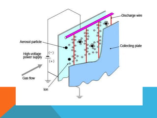
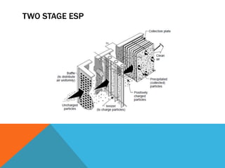


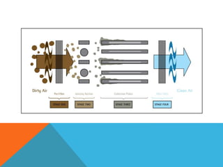
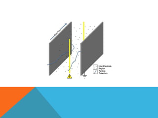


Electrostatic precipitators use electrostatic charges to remove particulate matter from gas streams. They apply a strong electric field between discharge electrodes and collection plates or tubes. This charges particles as they pass through, forcing them to collect on the plates or tubes. Periodically, the collected particles are removed from the plates by rapping or water spraying and collected in a hopper. Key components include discharge electrodes, collection surfaces, a high voltage power supply, and a particle removal system.


![ESP (STEAG) - Session 1 Part 2_ppt [Read-Only] [Compatibility Mode].pdf](https://cdn.slidesharecdn.com/ss_thumbnails/espsteag-session1part2pptread-onlycompatibilitymode-250605064152-25f30eb4-thumbnail.jpg?width=640&height=640&fit=bounds)


