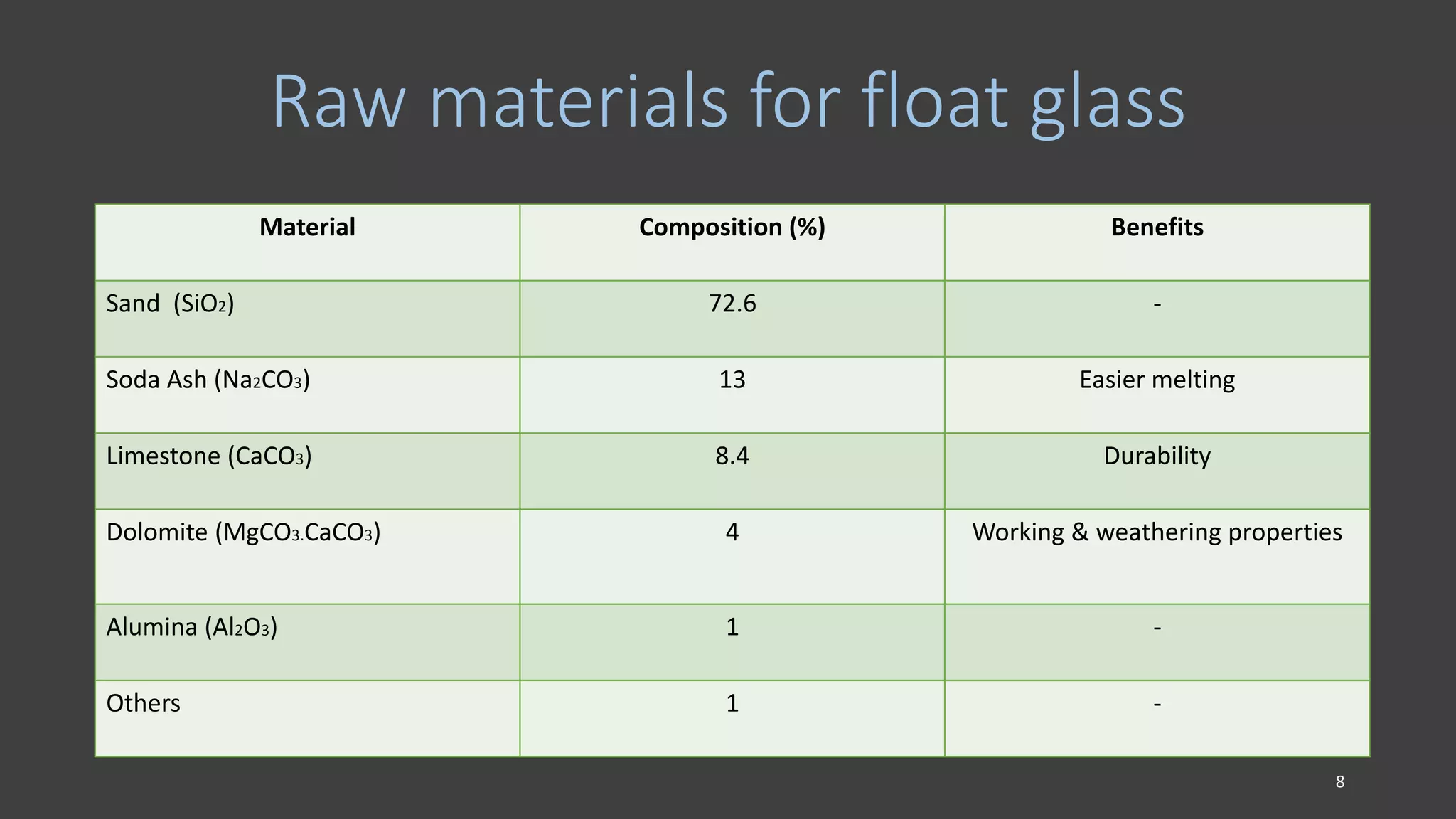
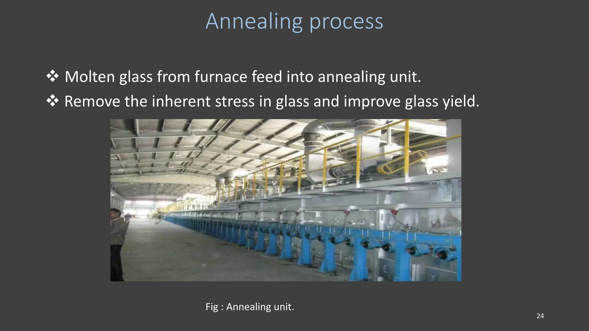
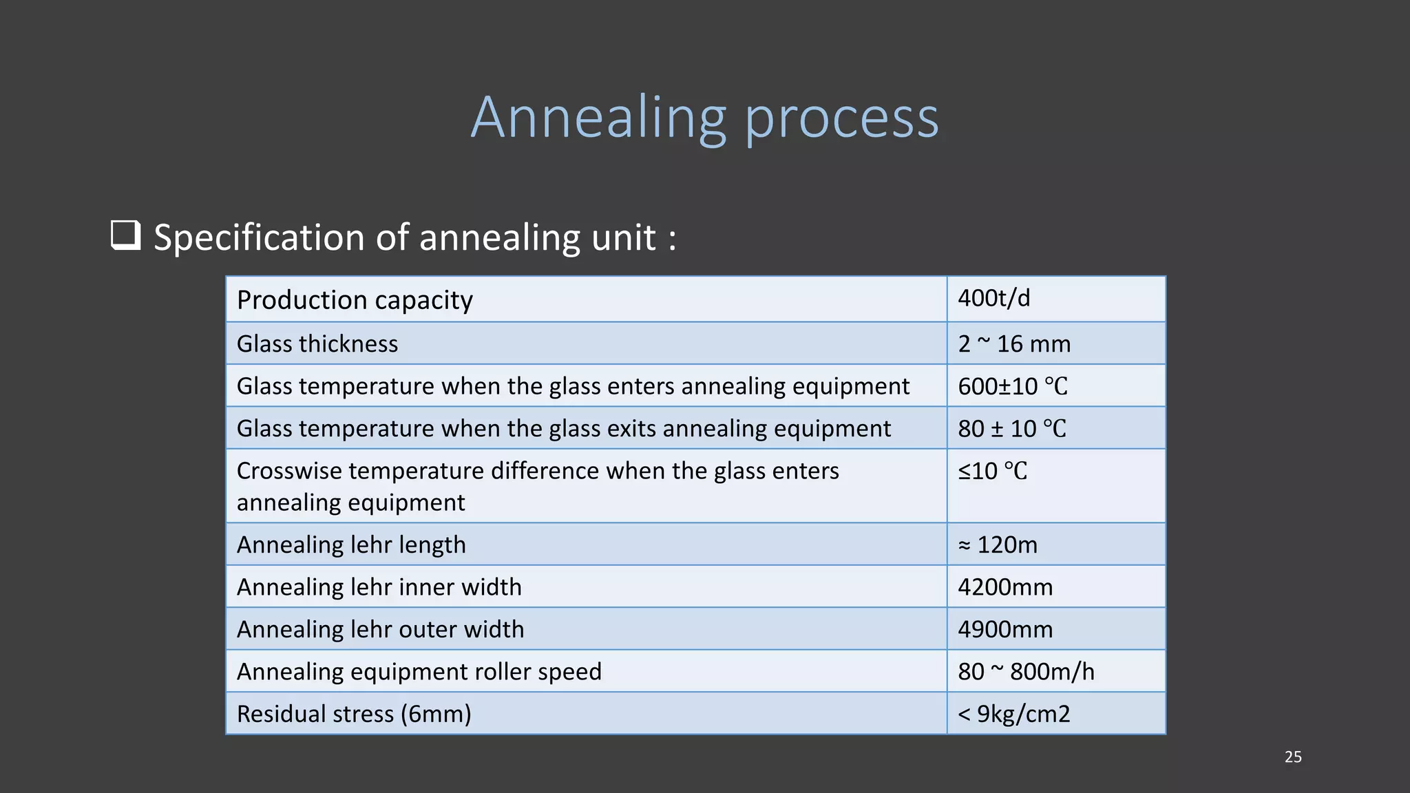
WELCOME
TO
OUR PRESENTATION
ON
Manufacturing process of glass
DEPARTMENT OF MECHANICAL ENGINEERING
DHAKA UNIVERSITY OF ENGINEERING &
TECHNOLOGY, GAZIPUR-1700.
1
TECHNICAL SEMINAR
ON
Nasir Glass Industries Limited
Joinabazar, Sreepur,
Gazipur, Bangladesh.
PRESENTED
BY
MD. Emamul Hossain
ID NO: 093100
MD. Rashadul Alam
ID NO: 093112
MD. Sultan Ahammed
ID NO: 093120
SUPERVISED BY
prof. Dr.Himangshu Bhowmik.
2
OBJECTIVES
 To take an idea about NGIL.
 To acquire knowledge on Glass manufacturing.
 To increase our knowledge about industrial application.
3
INTRODUCTION
Nasir Group, one of the largest renowned Group of Industries in Bangladesh .Specially it
is famous for its glass manufacturing Industries in Bangladesh and abroad .The Group is
proud of its lead for its many prestigious industries as a pioneer in Bangladesh. Nasir
Group is no longer simply a Group of Industries now-a-days, it has established its own
Brand Image in the country.
Fig : Nasir Glass Main Gate. Fig : Admin Building.
4
MISSION & VISION
The group’s mission and vision is to satisfy all of their clients providing quality
products with a competitive price through its companies innovation and
constant developments. This image has also crossed the border long before
,because some products are continuously being exported to some Asian,
Africa and Middle East countries like India, South Africa, Sri Lanka, Nepal,
Bhutan, Kenya etc. Nasir Group, originally a regional biri manufacturer based
in western Kushtia district, became a household name after setting up the
country’s first float glass factory. The Group is also the country’s biggest
melamine manufacturer, has a sports shoes plant and sells low-priced
cigarettes. The Group started January 1977. Nasir Group is also involved in
socio-cultural activities. Nasir Group has been operating some schools and
Colleges education in district town Kushtia. The Group has also acquired a
modern mother & children hospital.
5
Products of NGIL
 Float Glass (Clear &Tinted) : 100,000 MT/Annum/Under expansion
 Shade: clear, coffee bronze, Dark Gray, Ocean Blue, Green.
 Tempered Sheets: Clear/Tinted/Coated
 Mirrors: Standard sizes; Thickness 3, 4 & 5 mm; excellent finish.
 Thickness range: 3mm to 12mm (2mm also possible).
 Sizes of glass Product cut on line: Large size 84̋ X 144̋
Medium size 84̋ X 72̋
Small Size 42̋ X48̋
6
Flow chart of NGIL
7
Raw materials for float glass
Material Composition (%) Benefits
Sand (SiO2) 72.6 -
Soda Ash (Na2CO3) 13 Easier melting
Limestone (CaCO3) 8.4 Durability
Dolomite (MgCO3.CaCO3) 4 Working & weathering properties
Alumina (Al2O3) 1 -
Others 1 -
8
Raw material for glass
Fig: Silica Fig : Soda ash Fig : Dolomite
Fig : cullet. 9
Quality
International ; Strictly conforms to Chines National Standards GB11614-
1999 and GB/T 18701-2002 and Japanese National Standard J/S R3202.
Process
Fully automated with strict process control at every step from
sand processing to finished ware, backed up by highly trained
and experienced professionals. NGIL uses the best
technologies and the manufacturing process is strictly
controlled by the certified and skilled experts to ensure the
international standard.
10
Ore-dressing plant
 Main purpose of this plant is mainly to remove Iron & alumina.
 To maintain the size of silica.
 4 – 5% of water is maintained in the sand.
Fig : Slary pump. Fig : Sand crashing machine.
11
BATCH PLANT
 Batch plant is a very essential plant in NGIL.
 This plant is fully computerized.
 There are eight storage tank in this section.
 The amount of the elements are highly controlled.
 Specification of batch plant:
Weight of a batch 1300 Ton
Cullet (broken glass) 20%
Raw materials 80%
Fig : Raw material storage tank.
12
Regenerative furnace
 Specification of regenerative furnace
Capacity 400 t/d
Temperature 1500 -1600oc
Fuel (natural gas) 80000 – 90000 m3/day
Length 62 m
Width 25 m
Fuel : Air 1 : 7-10
Fig:- Regenerative furnace.
13
Regenerative furnace
Features
• high furnace capacity up to 400 t/d
• high quality glass for architecture or automotive purpose
• low energy consumption
• low emission values
14
Regenerative furnace
Working principle
• The furnace have two chamber.
• Refractory materials.
• Flow is reversed in every 20 min.
• Air is preheated heated by checker.
• preheat temperature 1200 – 1350 ˚C
Fig:- Regenerative furnace.
15
Tin bath
 Molten glass from furnace is fed into in bath.
 Tin bath contain molten tin.
 Density of glass is lower than tin.
 Glass is float on the tin.
 Viscous effect.
 N2 & H2 gasaresupplied.
 Specification
Length 50 m
Width 3-4 m
Depth 6 cm
Entering temperature 1100oc
Exit temperature 600oc
16
Fig : Inside view of the tin bath.
17
Nitrogen plant
 N2 is used to prevent corrosion of tin.
 The capacity of nitrogen plant is 2100 m3/h.
 Natural air is used as raw materials.
Fig: Nitrogen plant. 18
Working principle of nitrogen plant
Cleaning the air :
In a typical plant, air is drawn in through a filter to remove the dust,
compressed to about 6 atm and cooled to below ambient
temperature where much of the water vapour condenses.
Al2O3 : It is used to absorb CO2.
Zeolite molecule sieve : It is used to absorb H2O, CO, oil e.t.c.
19
Working principle of nitrogen plant
Liquefying the air
The manufacture of nitrogen, oxygen and argon from atmospheric air
involves liquefying the air and then separating it into its component
parts by fractional distillation. Since nitrogen and oxygen have very
low boiling points they liquefy at cryogenic temperatures.
Constituent helium neon nitrogen argon oxygen krypton xenon carbon
dioxide
Boiling
Point/K, at
atmospheri
c pressure
4 27 77 87 90 120 165 195
(sublimes)
Fig: The boiling points of the gases that make up dry air.
20
Working principle of nitrogen plant
Distillation of the liquid air
The liquid air is separated into its constituent components
by fractional distillation. At each distillation the vapour is richer in
nitrogen, while the liquid remaining contains more oxygen.
To produce pure oxygen the distillation system has two distillation
columns, a 'high' and a 'low' column. Nitrogen plants often use a
single column but some use two.
21
Hydrogen plant
 Hydrogen used in tin bath to prevent oxidation of glass.
 Chemical reaction : 2NH3 3H2 + N2
Fig : Ammonia cylinder. 22
Electric furnace
 Specification of electric furnace
Raw material NH3
Temperature 800 – 850 ᵒc
Power consumption 80 KW
Max. pressure 5.5 bar
Min. pressure 4 bar
Fig : Electric furnace.
23
Annealing process
 Molten glass from furnace feed into annealing unit.
 Remove the inherent stress in glass and improve glass yield.
Fig : Annealing unit.
24
Annealing process
 Specification of annealing unit :
Production capacity 400t/d
Glass thickness 2 ~ 16 mm
Glass temperature when the glass enters annealing equipment 600±10 ℃
Glass temperature when the glass exits annealing equipment 80 ± 10 ℃
Crosswise temperature difference when the glass enters
annealing equipment
≤10 ℃
Annealing lehr length ≈ 120m
Annealing lehr inner width 4200mm
Annealing lehr outer width 4900mm
Annealing equipment roller speed 80 ~ 800m/h
Residual stress (6mm) < 9kg/cm2
25
Annealing process
 Different zone of annealing unit :
Zone A, B & C No contact of air with glass.
Zone D, E Natural cooling.
Zone R1, R2, R3 Recirculation i.e direct contact of air supplied by blower.
Zone F1, F2 Direct contact of air supplied by nozzle.
Fig :Different zone of annealing unit.
26
Cutting & Finishing
 The cutting line is fully automatic.
 Carbide cutting tool is used.
 All roller are operated by main driving unit.
Fig : Main driving unit. Fig : Rollers connected with main driving unit.
27
Cutting & Finishing
Fig : carbide cutting tool. Fig : Automatic cutting line.
28
Final Product of NGIL
Fig : Final product of NGIL.
29
CONCLUSION
Today, more than ever, engineering are often interdisciplinary,
involving the interrelationship of several of the basic engineering
science. Therefore the modern engineer must have a fundamental
knowledge in each of these areas theoretical and practical. To make a
bridge between theoretical knowledge and practical knowledge by
arrange this type of industrial visiting resulted an engineer build up
own criteria very much widely in practical life.
30

Presentation on glass manufacturing

  • 1.
    WELCOME TO OUR PRESENTATION ON Manufacturing processof glass DEPARTMENT OF MECHANICAL ENGINEERING DHAKA UNIVERSITY OF ENGINEERING & TECHNOLOGY, GAZIPUR-1700. 1
  • 2.
    TECHNICAL SEMINAR ON Nasir GlassIndustries Limited Joinabazar, Sreepur, Gazipur, Bangladesh. PRESENTED BY MD. Emamul Hossain ID NO: 093100 MD. Rashadul Alam ID NO: 093112 MD. Sultan Ahammed ID NO: 093120 SUPERVISED BY prof. Dr.Himangshu Bhowmik. 2
  • 3.
    OBJECTIVES  To takean idea about NGIL.  To acquire knowledge on Glass manufacturing.  To increase our knowledge about industrial application. 3
  • 4.
    INTRODUCTION Nasir Group, oneof the largest renowned Group of Industries in Bangladesh .Specially it is famous for its glass manufacturing Industries in Bangladesh and abroad .The Group is proud of its lead for its many prestigious industries as a pioneer in Bangladesh. Nasir Group is no longer simply a Group of Industries now-a-days, it has established its own Brand Image in the country. Fig : Nasir Glass Main Gate. Fig : Admin Building. 4
  • 5.
    MISSION & VISION Thegroup’s mission and vision is to satisfy all of their clients providing quality products with a competitive price through its companies innovation and constant developments. This image has also crossed the border long before ,because some products are continuously being exported to some Asian, Africa and Middle East countries like India, South Africa, Sri Lanka, Nepal, Bhutan, Kenya etc. Nasir Group, originally a regional biri manufacturer based in western Kushtia district, became a household name after setting up the country’s first float glass factory. The Group is also the country’s biggest melamine manufacturer, has a sports shoes plant and sells low-priced cigarettes. The Group started January 1977. Nasir Group is also involved in socio-cultural activities. Nasir Group has been operating some schools and Colleges education in district town Kushtia. The Group has also acquired a modern mother & children hospital. 5
  • 6.
    Products of NGIL Float Glass (Clear &Tinted) : 100,000 MT/Annum/Under expansion  Shade: clear, coffee bronze, Dark Gray, Ocean Blue, Green.  Tempered Sheets: Clear/Tinted/Coated  Mirrors: Standard sizes; Thickness 3, 4 & 5 mm; excellent finish.  Thickness range: 3mm to 12mm (2mm also possible).  Sizes of glass Product cut on line: Large size 84̋ X 144̋ Medium size 84̋ X 72̋ Small Size 42̋ X48̋ 6
  • 7.
  • 8.
    Raw materials forfloat glass Material Composition (%) Benefits Sand (SiO2) 72.6 - Soda Ash (Na2CO3) 13 Easier melting Limestone (CaCO3) 8.4 Durability Dolomite (MgCO3.CaCO3) 4 Working & weathering properties Alumina (Al2O3) 1 - Others 1 - 8
  • 9.
    Raw material forglass Fig: Silica Fig : Soda ash Fig : Dolomite Fig : cullet. 9
  • 10.
    Quality International ; Strictlyconforms to Chines National Standards GB11614- 1999 and GB/T 18701-2002 and Japanese National Standard J/S R3202. Process Fully automated with strict process control at every step from sand processing to finished ware, backed up by highly trained and experienced professionals. NGIL uses the best technologies and the manufacturing process is strictly controlled by the certified and skilled experts to ensure the international standard. 10
  • 11.
    Ore-dressing plant  Mainpurpose of this plant is mainly to remove Iron & alumina.  To maintain the size of silica.  4 – 5% of water is maintained in the sand. Fig : Slary pump. Fig : Sand crashing machine. 11
  • 12.
    BATCH PLANT  Batchplant is a very essential plant in NGIL.  This plant is fully computerized.  There are eight storage tank in this section.  The amount of the elements are highly controlled.  Specification of batch plant: Weight of a batch 1300 Ton Cullet (broken glass) 20% Raw materials 80% Fig : Raw material storage tank. 12
  • 13.
    Regenerative furnace  Specificationof regenerative furnace Capacity 400 t/d Temperature 1500 -1600oc Fuel (natural gas) 80000 – 90000 m3/day Length 62 m Width 25 m Fuel : Air 1 : 7-10 Fig:- Regenerative furnace. 13
  • 14.
    Regenerative furnace Features • highfurnace capacity up to 400 t/d • high quality glass for architecture or automotive purpose • low energy consumption • low emission values 14
  • 15.
    Regenerative furnace Working principle •The furnace have two chamber. • Refractory materials. • Flow is reversed in every 20 min. • Air is preheated heated by checker. • preheat temperature 1200 – 1350 ˚C Fig:- Regenerative furnace. 15
  • 16.
    Tin bath  Moltenglass from furnace is fed into in bath.  Tin bath contain molten tin.  Density of glass is lower than tin.  Glass is float on the tin.  Viscous effect.  N2 & H2 gasaresupplied.  Specification Length 50 m Width 3-4 m Depth 6 cm Entering temperature 1100oc Exit temperature 600oc 16
  • 17.
    Fig : Insideview of the tin bath. 17
  • 18.
    Nitrogen plant  N2is used to prevent corrosion of tin.  The capacity of nitrogen plant is 2100 m3/h.  Natural air is used as raw materials. Fig: Nitrogen plant. 18
  • 19.
    Working principle ofnitrogen plant Cleaning the air : In a typical plant, air is drawn in through a filter to remove the dust, compressed to about 6 atm and cooled to below ambient temperature where much of the water vapour condenses. Al2O3 : It is used to absorb CO2. Zeolite molecule sieve : It is used to absorb H2O, CO, oil e.t.c. 19
  • 20.
    Working principle ofnitrogen plant Liquefying the air The manufacture of nitrogen, oxygen and argon from atmospheric air involves liquefying the air and then separating it into its component parts by fractional distillation. Since nitrogen and oxygen have very low boiling points they liquefy at cryogenic temperatures. Constituent helium neon nitrogen argon oxygen krypton xenon carbon dioxide Boiling Point/K, at atmospheri c pressure 4 27 77 87 90 120 165 195 (sublimes) Fig: The boiling points of the gases that make up dry air. 20
  • 21.
    Working principle ofnitrogen plant Distillation of the liquid air The liquid air is separated into its constituent components by fractional distillation. At each distillation the vapour is richer in nitrogen, while the liquid remaining contains more oxygen. To produce pure oxygen the distillation system has two distillation columns, a 'high' and a 'low' column. Nitrogen plants often use a single column but some use two. 21
  • 22.
    Hydrogen plant  Hydrogenused in tin bath to prevent oxidation of glass.  Chemical reaction : 2NH3 3H2 + N2 Fig : Ammonia cylinder. 22
  • 23.
    Electric furnace  Specificationof electric furnace Raw material NH3 Temperature 800 – 850 ᵒc Power consumption 80 KW Max. pressure 5.5 bar Min. pressure 4 bar Fig : Electric furnace. 23
  • 24.
    Annealing process  Moltenglass from furnace feed into annealing unit.  Remove the inherent stress in glass and improve glass yield. Fig : Annealing unit. 24
  • 25.
    Annealing process  Specificationof annealing unit : Production capacity 400t/d Glass thickness 2 ~ 16 mm Glass temperature when the glass enters annealing equipment 600±10 ℃ Glass temperature when the glass exits annealing equipment 80 ± 10 ℃ Crosswise temperature difference when the glass enters annealing equipment ≤10 ℃ Annealing lehr length ≈ 120m Annealing lehr inner width 4200mm Annealing lehr outer width 4900mm Annealing equipment roller speed 80 ~ 800m/h Residual stress (6mm) < 9kg/cm2 25
  • 26.
    Annealing process  Differentzone of annealing unit : Zone A, B & C No contact of air with glass. Zone D, E Natural cooling. Zone R1, R2, R3 Recirculation i.e direct contact of air supplied by blower. Zone F1, F2 Direct contact of air supplied by nozzle. Fig :Different zone of annealing unit. 26
  • 27.
    Cutting & Finishing The cutting line is fully automatic.  Carbide cutting tool is used.  All roller are operated by main driving unit. Fig : Main driving unit. Fig : Rollers connected with main driving unit. 27
  • 28.
    Cutting & Finishing Fig: carbide cutting tool. Fig : Automatic cutting line. 28
  • 29.
    Final Product ofNGIL Fig : Final product of NGIL. 29
  • 30.
    CONCLUSION Today, more thanever, engineering are often interdisciplinary, involving the interrelationship of several of the basic engineering science. Therefore the modern engineer must have a fundamental knowledge in each of these areas theoretical and practical. To make a bridge between theoretical knowledge and practical knowledge by arrange this type of industrial visiting resulted an engineer build up own criteria very much widely in practical life. 30