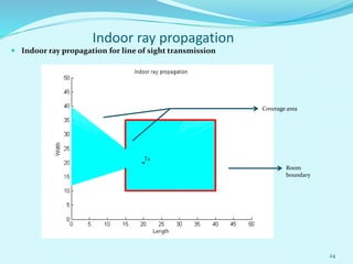
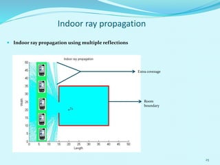
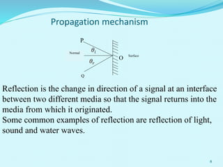
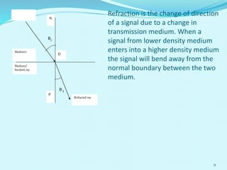
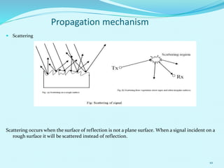
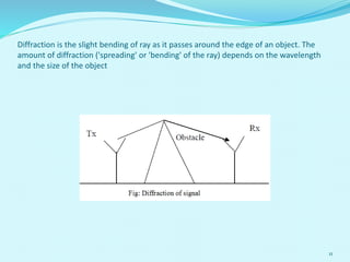
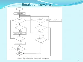
This document summarizes a thesis presentation on simulating indoor and outdoor radio wave propagation using MATLAB. The presentation covers propagation mechanisms like line of sight, reflection, refraction, scattering and diffraction. It describes simulating these mechanisms using MATLAB to calculate received power and signal strength. Validation of the simulation model is done by considering free space propagation. Indoor ray propagation is also simulated to analyze coverage using line of sight and multiple reflections.

![ Transmission
MATLAB code for Transmission
tx_x=16;
tx_y=20;
n_ray=input('Total number of rays:');
r=45;
for n=1:n_ray;
theta=(n-1)*360/n_ray*pi/180;
a(n)=r*cos(theta)+tx_x;
b(n)=r*sin(theta)+tx_y;
plot([tx_x a(n)],[tx_y b(n)],'k');
end
Obstacle
MATLAB code for obstacles
obstacle=[36 36];
obstacle=[12 40];
plot(obstacle_x,obstacle_y,'k','LineWidth',3);
14
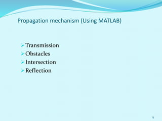
Propagation mechanism (Using MATLAB)](https://image.slidesharecdn.com/presentation-160314094207/85/Presentation-14-320.jpg)
![ Intersection
MATLAB code for Transmission
[xi,yi]=polyxpoly([20 a(n)],[20 b(n)],[36 36],[12 40]);
Reflection
MATLAB code for Transmission
for m=1:i;
theta=180*pi/180-reflect_angle;
c= r*cos(theta)+intersect_x(m);
d= r*sin(theta)+intersect_y(m);
plot([intersect_x(m) c(m)],[intersect_y(m) d(m)],'r');
end
15
Propagation mechanism (Using MATLAB)](https://image.slidesharecdn.com/presentation-160314094207/85/Presentation-15-320.jpg)