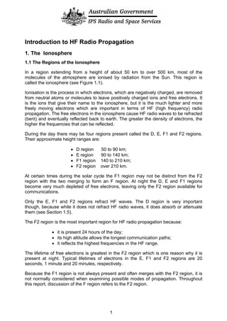
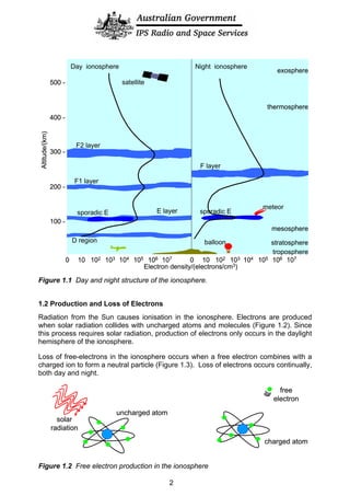
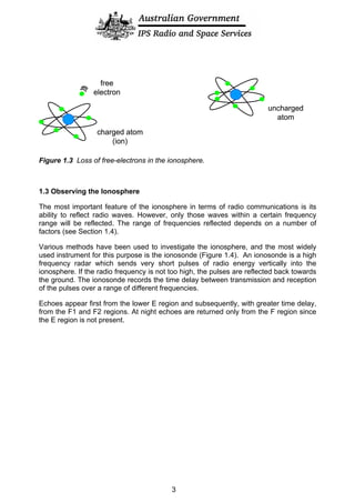
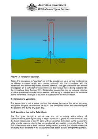
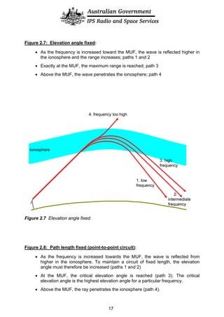
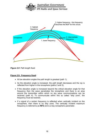
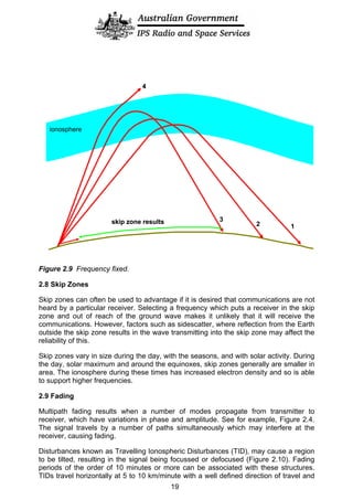
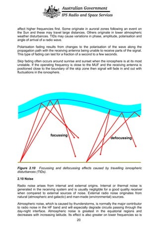
The document discusses the ionosphere, which is the region of Earth's atmosphere from about 50-500 km above the surface that is ionized by solar radiation. It has four main layers (D, E, F1, F2) that refract radio waves to different degrees. The F2 layer is most important for HF radio propagation as it is present day and night and can reflect the highest frequencies. The ionosphere varies based on the solar cycle, seasons, time of day, and latitude, which affects the usable radio frequencies for communication.
RADAR stands for Radio Detection and Ranging. It uses electromagnetic waves to detect the position, velocity, and characteristics of targets. RADAR was originally developed for military purposes during World War 2, when it was used by the British and US militaries to locate ships and airplanes. Today, RADAR is an essential tool for weather prediction and analysis. Different types of RADAR include pulse transmission RADAR and continuous wave RADAR. RADAR comes in various forms such as search RADAR for detection and tracking RADAR for following individual targets. The frequency used depends on the desired range, with lower frequencies allowing longer detection distances.
Design and Simulation Microstrip patch Antenna using CST Microwave StudioAymen Al-obaidi
The document describes the design and simulation of a microstrip patch antenna in CST Microwave Studio. It begins with an introduction to microstrip patch antennas and their applications. Then, it outlines the theoretical design of a rectangular patch antenna for 2.4 GHz WiFi using transmission line equations. Finally, it details the simulation process in CST Microwave Studio, including adding the patch, feedline, substrate and ground plane, assigning materials and frequencies, setting up the port and monitors, and solving to obtain results like the bandwidth and radiation pattern.
The document discusses various aspects of radio wave propagation. It explains that radio waves travel through the ionosphere and can be refracted back to Earth, allowing long distance communication. The ionosphere consists of several layers (D, E, F1, F2) that reflect radio waves of different frequencies depending on factors like solar activity and time of day. Radio propagation involves line-of-sight transmission as well as skywave propagation via reflection/refraction from ionospheric layers, which can allow signals to hop or skip distances beyond the horizon through multiple reflections. Absorption, fading, and noise affect signal strength over distance.
This document discusses various topics related to radio wave propagation including:
1. Modes of propagation such as ground wave, sky wave, and space wave propagation. Sky wave propagation involves signal reflection from ionized layers in the atmosphere.
2. Characteristics of the ionospheric layers including the D, E, F1, and F2 layers which vary in ionization levels and affect the maximum usable frequency.
3. Key concepts in sky wave propagation such as virtual height, skip distance, maximum usable frequency, and how daylight impacts absorption and refraction of signals.
An active phased array radar system uses a digital beamforming architecture with transmit/receive modules behind each radiating antenna element. This distributed amplifier approach improves noise figure and clutter attenuation compared to passive arrays. Digital beamforming allows formation of multiple simultaneous beams and improved dynamic range. Dual polarized arrays can operate in different modes like alternating transmit and simultaneous receive to measure linear depolarization ratios. Future trends include integrating more components into the antenna and using wideband semiconductor devices.
Millimeter wave mobile communication has several advantages over traditional cellular frequencies. It utilizes the 30-300GHz spectrum which has much larger channel bandwidths available, enabling significantly higher data rates. Key benefits include multi-Gbps speeds, narrow beams allowing frequency reuse, and inherent security. However, mm-waves also have challenges including higher attenuation over distance, difficulty passing through walls, and interference from rain and oxygen. Potential applications include small cell 5G networks, wireless backhaul between small cells, and outdoor coverage up to 300 meters using beamforming.
Satellite communication allows people to communicate across long distances. Arthur C. Clarke first proposed the idea of communication satellites in 1945. The first satellite launched was Sputnik 1 by Russia in 1957, though it did not have communication capabilities. Commercial satellite communication began with the launch of Early Bird in 1965. Satellites can be in low, medium or geostationary orbits and operate in different frequency bands like C-band and Ku-band. They provide advantages like global coverage and reliability over terrestrial networks.
The document discusses different types of radar systems and their components and principles of operation. It covers topics like pulse radar vs continuous wave radar, components of each type of system like transmitter, receiver, antennas, and how factors like pulse width, repetition frequency and power affect radar performance and capabilities. It also discusses modulation techniques, antenna beam formation, and different types of radar displays.
This document discusses electromagnetic waves and their propagation. It begins by defining electromagnetic waves and their properties such as being transverse waves that propagate through free space at the speed of light. It then discusses how EM waves spread uniformly in all directions from a point source, forming spherical wavefronts. The document goes on to describe different types of EM wave propagation including ground waves, space waves, and sky waves that propagate via reflection off the ionosphere. Key factors that influence EM wave propagation like frequency, transmitter power, and atmospheric conditions are also summarized.
Millimeter waves is considered as a key enabling technology for the future wireless networks, 5G network.
To that end, these simple slides go further in the motivation, characteristics, applications, and many others related to the mmWaves.
enjoy .. :)
The document summarizes key concepts about radio wave propagation including:
- Radio waves are transmitted from antennas and can propagate through line of sight transmission, reflection off the ionosphere (skywaves), or along the ground (groundwaves).
- The ionosphere, ionized by solar radiation, is made up of layers (D, E, F1, F2) that refract radio waves to different extents based on frequency and solar activity.
- Solar activity and sunspots influence ionization and radio propagation, with higher activity providing better long-distance propagation via skywaves.
This document provides an overview of wireless communication technologies. It discusses why wireless communication is useful by allowing freedom from wires and global coverage. It defines wireless communication as transmitting voice and data using electromagnetic waves. It then covers typical frequency ranges used, how communication takes place, types of wireless communication including radio transmission and infrared waves. Current wireless systems like cellular, wireless LANs, and satellite systems are described along with Bluetooth, NFC, Wi-Fi and Li-Fi technologies.
The document discusses the history and components of radar systems. It describes how radar works by transmitting pulses that reflect off targets and return to the radar's receiver. Key radar observables are discussed like target range, angle, size, speed and features. The document also covers different types of radar including pulse and continuous wave, and various applications such as air traffic control, weather monitoring, and military uses. It concludes by discussing emerging radar technologies.
1. Kepler's laws of planetary motion describe the motion of planets and satellites in orbit. The orbital period is determined by the semimajor axis of the elliptical orbit.
2. A geostationary orbit is circular, at an altitude that matches the orbital period to Earth's sidereal day, and in the equatorial plane. A geosynchronous orbit has the correct period but may have eccentricity or inclination.
3. Orbital elements like eccentricity, semimajor axis, inclination and nodes define the characteristics of Earth-orbiting satellites. Perturbations from factors like the Sun and Moon cause the orbital elements and position to change over time.
This document discusses different types of antennas, including horn antennas, slot antennas, microstrip or patch antennas, quad-helix antennas, and notch antennas. It provides details on the purpose, design, and applications of each antenna type. Horn antennas are used to direct radio waves in a beam from a waveguide and have high gain. Slot antennas consist of a metal surface with a cut-out hole or slot that radiates waves similarly to a dipole antenna. Microstrip antennas can be printed on circuit boards and are widely used in mobile devices due to their low cost. Quad-helix antennas have four connected helix antennas and transmit measurements from remote areas. Notch antennas operate based on a cut-out section similar to
MicroStrip Antenna
Introduction .
Micro-Strip Antennas Types .
Micro-Strip Antennas Shapes .
Types of Substrates (Dielectric Media) .
Comparison of various types of flat profile printed antennas .
Advantages & DisAdvantages of MSAs .
Applications of MSAs .
Radiation patterns of MSAs .
How to Optimizing the Substrate Properties for Increased Bandwidth ?
Comparing the different feed techniques .
1) Millimeter wave spectrum offers huge amounts of bandwidth that can enable multi-Gbps wireless networks. Advances in technology now make using millimeter wave spectrum possible for consumer devices.
2) Standards have been developed for the 60GHz unlicensed band, and compliant products are now available, achieving multi-Gbps speeds. However, they currently only support single-stream MIMO beamforming.
3) Millimeter wave networks can provide significantly higher data rates than traditional cellular networks through the use of large antenna arrays and beamforming to overcome propagation losses, along with wider channel bandwidths.
Geostationary satellites orbit approximately 22,300 miles above the Earth's equator. They maintain a constant position relative to locations on Earth's surface. This allows them to be used for telecommunications and weather observation applications. Geostationary satellites have advantages like high coverage area from a small number of satellites, but also disadvantages like inability to observe polar regions and weak signals from long distances.
Free space optical communication(final)kanusinghal3
This document provides an overview of free space optical communication (FSO). It discusses the motivation for using FSO due to increasing bandwidth needs and spectrum scarcity. FSO uses visible or infrared light to transmit broadband communications in a line-of-sight fashion. The document outlines key challenges of FSO including attenuation from environmental factors like fog and scattering. It also reviews the advantages of low cost and high security as well as disadvantages such as sensitivity to obstructions. The document concludes that FSO is a promising supplemental technology to wireless and fiber for short-range applications.
The document discusses signal selection criteria and remedies for satellite navigation systems like GPS. It covers 5 criteria: 1) acceptable received power levels with reasonable antenna patterns and ionospheric delay, remedied by choosing L-band frequency. 2) rejection of multipath signals using circular polarization. 3) meeting power spectral density constraints using spread spectrum signaling. 4) providing multiple access using code division multiple access (CDMA). 5) providing ionospheric correction using dual frequencies like L1 and L2. It provides details on GPS signal frequencies, modulation, and PRN codes.
Satellite communication provides long distance communication by using satellites to transmit signals between locations on Earth. There are three types of satellites - active satellites that amplify and change the frequency of signals, passive satellites that simply reflect signals, and broadcasting satellites used for radio and television. Satellites orbit Earth in different patterns depending on their inclination and eccentricity. Key elements of satellite communication systems are the space segment including satellites, and the ground segment including earth stations. Satellite communication services can be one-way, such as broadcasting, or two-way, such as telephone calls.
This document discusses the history and basics of satellite communication systems. It covers:
- The first satellites launched in the 1940s-1990s and the development of satellite phone systems.
- The types of satellite orbits including LEO, MEO, and GEO and how factors like altitude and inclination determine satellite period and coverage areas.
- How satellite systems extend cellular networks to provide global mobile communication through techniques like inter-satellite links and handovers between satellites and gateways.
- The challenges of satellite systems including higher latency compared to terrestrial networks and the need for complex routing and localization as satellites move.
This document provides information on fundamental antenna parameters and concepts. It discusses:
1. How antennas convert guided waves into radiating waves and vice versa.
2. Key antenna parameters including radiation pattern, directivity, radiation resistance, efficiency, gain, bandwidth, reciprocity, effective aperture, beamwidth, and polarization matching.
3. The Friis transmission formula for calculating received power between two antennas in free space based on their gains, wavelength, and distance.
A transponder is a device on a satellite that receives transmitted signals from an Earth station on an uplink frequency, amplifies the signals, and retransmits them on a downlink frequency to Earth. It functions as both a repeater and a frequency converter in space. Transponders are classified as either nonregenerative or regenerative. Nonregenerative transponders only alter the signal's amplitude and frequency, while regenerative transponders also alter the received signal before demodulation to offer flexibility in optimizing transmission link performance.
The document discusses satellite communications, including the basic components and orbits of communication satellites, how they are used to transmit signals, and some of their applications such as television, radio, and mobile phones. Key orbits discussed include LEO, MEO, and GEO orbits, and the advantages and disadvantages of each for communication purposes. The document also covers frequency allocation and some of the challenges of using satellites for communication.
The document discusses the benefits of exercise for mental health. Regular physical activity can help reduce anxiety and depression and improve mood and cognitive functioning. Exercise causes chemical changes in the brain that may help protect against mental illness and improve symptoms.
Nav Topic 2 modulation and propagation of radio wavesIzah Asmadi
The document discusses different types of radio wave modulation and propagation. It describes how a carrier wave carries information from the transmitter to the receiver using amplitude modulation (AM), frequency modulation (FM), or single sideband (SSB). It also explains the different paths radio waves can take, including surface waves, sky waves, and space waves, which depend on the frequency. Higher frequencies above 3 MHz use line-of-sight space wave propagation while lower frequencies may be reflected off the ionosphere as sky waves or follow the curvature of the Earth as surface waves. The length of the radio wave depends inversely on its frequency.
This is a presentation outlining the beginnings of Amateur radio in the early 1900s to the present day. There are 37 slides from the the Spark era to the rise of the internet within our hobby. Anyone is welcome to use any of this material if they presenting a similar talk.
Gujarat Institute of Amateur Radio provides training and resources for amateur ("ham") radio operators. During disasters, ham radio is often the only form of communication when other systems fail. The document outlines ham radio's role in past disasters in India and how it works, including requirements to become a licensed operator and typical communications methods like VHF, HF radio and satellites.
This document provides an introduction to HF (high frequency) radio for new amateur radio operators. It discusses key topics like HF propagation via reflection from ionosphere layers, different types of propagation, radio controls and features, antenna types, and getting started in HF radio with an inexpensive transceiver and simple wire antenna. The goal is to explain the basics of HF radio in an accessible way to spark interest in communicating over long distances using this mode of amateur radio.
This document discusses comets, asteroids, and meteors. Comets are dirty balls of ice that develop tails when passing near the sun. Asteroids are large chunks of rock and metal that orbit the sun. When asteroids and comet fragments enter Earth's atmosphere, they are called meteoroids. Most burn up and are seen as meteors, also known as shooting stars. If fragments survive entry and reach the ground, they are called meteorites. Large impacts from asteroids or comets in the past have created craters and possibly contributed to mass extinctions like the dinosaurs.
The International Telecommunication Union (ITU) coordinates global spectrum management and telecommunication standards between countries to enable radio communications worldwide. The Federal Communications Commission (FCC) regulates radio transmissions and issues licenses within the United States, setting technical standards and managing spectrum allocation for various services like amateur radio within U.S. borders. In amateur radio, signals from nearby stations are called local contacts while distant stations are referred to as DX contacts, with DX being an abbreviation for distance in Morse code.
The document outlines the topics to be covered in a Digital Technology Merit Badge program, including the history of computers, types of data storage and memory, computer networks and the internet, applications and programs, online safety, intellectual property rights, recycling, and computer-related careers. Participants will learn about early computers, the development of integrated circuits and microprocessors, and modern personal devices. They will also cover networking basics, file types and storage, and protecting devices from malware and privacy risks online.
The document discusses ionosphere modeling and tomography. It aims to learn the temporal and spatial variation of the ionosphere to improve GNSS performance and protect satellites from adverse space environments. Data from 183 stations on May 15, 2012 was used with a 15 degree, 15 order spherical harmonics function to model coefficients, satellite differential code biases, and receiver differential code biases. A simulation of local ionosphere tomography in Hong Kong on May 4, 2009 was also performed.
This document discusses the ionosphere and its role in radio propagation. It provides details on the different layers of the ionosphere (D, E, F1, and F2 layers), how they vary in temperature and electron densities. It explains that the ionosphere consists of ionized particles that behave as plasma and are affected by solar activity like flares and sunspots. The document also discusses how the ionosphere facilitates radio communication by reflecting radio waves back to Earth, allowing transmissions to travel farther than if they simply traveled in straight lines.
Digital Technology Merit Badge - Boy Scouts of America
Powerpoint used for the 2015 Carlisle Merit Badge College, Carlisle, PA, New Birth of Freedom Council, Pioneer District.
The document summarizes key aspects of amplitude modulation (AM) including:
1. AM varies the amplitude of a carrier wave based on the instantaneous amplitude of a modulating signal. This imparts the modulating signal's information onto the carrier wave.
2. The derivation of an AM wave shows it can be expressed as the carrier wave amplitude multiplied by the sum of 1 and the modulating signal, which varies the carrier amplitude.
3. The modulation index is defined as the ratio of the modulating signal amplitude to the carrier amplitude, and describes how much the carrier amplitude varies with respect to its unmodulated level.
This document discusses radio wave propagation and the ionosphere. It begins by introducing concepts like radio refractive index and how radio waves interact with and are reflected by the ionosphere. It then discusses how the ionosphere affects radio propagation by causing refraction, reflection, and absorption of radio waves. Specifically, it explains how radio waves are refracted or reflected depending on the electron density in different layers of the ionosphere. It also describes two types of high frequency radio propagation: ground-wave propagation over short distances and sky-wave propagation over longer distances via reflection from the ionosphere.
This slide contains the content about earth's atmosphere. You will able to know about different layers of atmosphere and radio wave propagation through atmospheric layers.
The document discusses various topics related to wave propagation including:
- Types of waves such as transverse and longitudinal waves.
- Electromagnetic waves and their properties like traveling through space without a medium and as vibrations in electric and magnetic fields.
- How sun activity and solar cycles impact the ionosphere and affect HF radio propagation over long distances.
- Atmospheric layers like the troposphere, stratosphere, and ionosphere that electromagnetic waves interact with.
There are two types of electronic communication: simplex and duplex. Simplex is one-way communication while duplex allows two-way communication.
Electromagnetic waves can propagate through the air in two ways: longitudinal and transverse. Radio waves can travel from the transmitting to receiving antenna through two paths: ground waves and sky waves. Ground waves travel along the earth's surface while sky waves are reflected back to earth by the ionosphere.
The ionosphere affects electromagnetic wave propagation at communication frequencies. It is divided into layers D, E, and F which refract radio waves differently based on factors like electron density, frequency, and angle of incidence.
This document discusses radio wave propagation through the ionosphere. It begins by outlining the syllabus which includes factors affecting propagation such as the ground wave, ionosphere effects, refraction, reflection, skip distance and fading. It then discusses these factors in more detail over 3 pages, explaining ground wave propagation, the structure of the ionosphere consisting of E, F1, F2 and D layers, and how radio waves are refracted and reflected by the ionosphere to allow communication beyond line of sight.
The document discusses radio wave propagation through the ionosphere. It describes the three main layers of the ionosphere - the D layer, E layer, and F layer. The D layer absorbs lower radio frequencies during the day. The E layer supports short-range propagation during the day. The F layer, divided into F1 and F2, is responsible for long-distance high frequency propagation, especially at night when the layers merge. Ground wave propagation travels along the ground, while skywave propagation involves reflection from the ionosphere.
Radio waves are electromagnetic waves characterized by frequency and wavelength. They propagate through various behaviors when interacting with different mediums, including reflection, refraction, and diffraction. Ground wave propagation involves direct and reflected waves traveling near the Earth's surface, while skywave propagation uses the ionosphere to refract signals back to Earth over greater distances. The ionosphere consists of layers that are ionized by solar radiation and influence maximum usable frequencies. Solar effects like daily variations, sunspots, and solar flares impact ionization levels and radio wave propagation. Different frequency bands like HF, VHF, UHF each have their own characteristics and uses for military communications.
Radio propagation is affected by various factors in the atmosphere including water vapor, ionization, and solar activity. Understanding how radio waves propagate under different conditions has practical applications for broadcasting, mobile phones, radar, and radio navigation. Propagation can occur through line-of-sight transmission, reflection from the ionosphere, or scattering from the troposphere, and the dominant mode depends on the frequency used and conditions in the atmosphere and ionosphere. Predicting radio propagation is complex due to changing environmental conditions.
Ground waves propagate along the Earth's surface and are used for medium wave (MW) transmissions. Space waves travel in straight lines but are limited by the curvature of the Earth. Sky waves are used for short wave (SW) transmissions and reflect off the ionosphere which consists of layers (D, E, F1, F2) that vary in density and thickness depending on the time of day and sun exposure. Different propagation modes are used depending on the frequency band and conditions to maximize transmission range.
Radio waves can propagate through free space or be guided by surfaces like the ground or the ionosphere. The key layers of the ionosphere that influence radio propagation are the D, E, and F layers. The F layer, consisting of the F1 and F2 sublayers, is the most important for long-distance radio communications as it remains partially ionized at night. Radio signals can be reflected or refracted by the ionized layers of the ionosphere, allowing skywave propagation over long distances beyond the horizon.
The document discusses photovoltaic devices and solar cells. It begins by introducing photovoltaic devices and how they convert solar radiation into electrical energy. It then discusses the solar energy spectrum and how sunlight intensity is affected by atmospheric absorption and scattering. The principles of photovoltaic devices are explained, including how photons are absorbed to generate charge carriers, and the operation of pn junction solar cells. Applications ranging from small electronics to large solar power plants are mentioned. Key factors that influence solar cell efficiency such as materials properties, surface recombination, and wavelength absorption are analyzed.
This document provides an overview of radio wave propagation and the ionosphere. It defines key concepts like ground wave propagation, sky wave propagation, space wave propagation, critical frequency, maximum usable frequency, and ray path. It describes how the ionosphere is structured in layers and how radio waves interact with and are refracted or reflected by the ionized layers, affecting long-distance radio communication. Factors that influence radio wave propagation like frequency, angle of incidence, and solar activity are also discussed.
The document discusses radio wave propagation and the factors that affect it. It covers topics like the ionosphere and how it influences radio waves, propagation modes like ground waves and sky waves, absorption and fading effects, and how solar activity impacts radio communications through changes in the ionosphere. Key points are that the ionosphere is made up of layers that refract radio waves to allow long distance communications, but that solar activity and sunspots impact the ionosphere's composition and ability to support different frequencies.
Sky wave propagation involves radio waves reflecting off ionized layers in the upper atmosphere, called the ionosphere, between 50-400km above the Earth's surface. This allows radio signals to travel beyond the horizon over very long distances of thousands of kilometers. The ionosphere is divided into D, E, and F layers based on ionization density, with the F layers primarily responsible for radio wave refraction. Sky wave propagation has enabled long-distance shortwave radio communication between 3-30MHz and amateur radio communication over long distances.
This document discusses electromagnetic wave propagation. Electromagnetic waves consist of oscillating electric and magnetic fields that propagate through space at the speed of light. They include radio waves, light, X-rays and gamma rays. Radio waves propagate through space as transverse electromagnetic waves and their speed depends on the medium. The wavelength is determined by the frequency and phase velocity. Power density decreases with distance from the source according to the inverse square law. Reflection, refraction, diffraction and polarization affect wave propagation. Terrestrial propagation is influenced by the curvature of the Earth and the atmosphere, especially the ionosphere.
This document discusses radio wave propagation. It begins by revisiting transverse electromagnetic waves and their properties. It then discusses different parameters of radio waves like frequency, wavelength, polarization, and intrinsic impedance. It describes various modes of propagation including ground waves, sky waves, and space waves. Ground waves travel along the Earth's surface up to 2 MHz. Sky waves are reflected by the ionosphere to propagate over longer distances on HF bands. Space waves use line-of-sight propagation on VHF and UHF bands. The document also reviews optical properties like reflection, diffraction and interference experienced by radio waves.
Communication - Space Communication Class 12 Part-5Self-employed
This document provides an overview of space communication and satellite technology. It discusses key topics such as electromagnetic wave propagation through ground waves, sky waves, and space waves. It describes how communication satellites in geostationary orbit facilitate global communication through transponders that receive and retransmit signals. Remote sensing satellites are also summarized, including their sun-synchronous orbits and wide range of applications in areas like geology, agriculture, defense, and environmental monitoring.
Radio waves propagating through space exhibit electric and magnetic fields that are oriented perpendicular to each other and the direction of propagation. Polarization describes the orientation of these oscillating fields and can be linear, circular, or elliptical. For Earth-Moon-Earth (EME) communications, linear polarization is typically used below 432MHz to minimize signal losses from polarization rotation caused by propagation through the ionosphere, which can exceed 1dB for rotations greater than 20-30 degrees. Faraday rotation, proportional to electron density and wavelength squared, further contributes to polarization rotation as radio waves pass through the ionosphere.
Radio waves can propagate from the transmitter to the receiver via three main ways: ground waves, sky waves, and space waves. Ground waves travel along the earth's surface for short-range communication. Sky waves travel upward and reflect off ionized layers in the ionosphere to allow long-range communication. Space waves travel directly through the air but are affected by factors like atmospheric conditions, earth curvature, and heights of transmitting and receiving antennas. The distance radio waves can propagate depends on the transmission method used and various environmental factors.
HCL Notes und Domino Lizenzkostenreduzierung in der Welt von DLAUpanagenda
Webinar Recording: https://www.panagenda.com/webinars/hcl-notes-und-domino-lizenzkostenreduzierung-in-der-welt-von-dlau/
DLAU und die Lizenzen nach dem CCB- und CCX-Modell sind für viele in der HCL-Community seit letztem Jahr ein heißes Thema. Als Notes- oder Domino-Kunde haben Sie vielleicht mit unerwartet hohen Benutzerzahlen und Lizenzgebühren zu kämpfen. Sie fragen sich vielleicht, wie diese neue Art der Lizenzierung funktioniert und welchen Nutzen sie Ihnen bringt. Vor allem wollen Sie sicherlich Ihr Budget einhalten und Kosten sparen, wo immer möglich. Das verstehen wir und wir möchten Ihnen dabei helfen!
Wir erklären Ihnen, wie Sie häufige Konfigurationsprobleme lösen können, die dazu führen können, dass mehr Benutzer gezählt werden als nötig, und wie Sie überflüssige oder ungenutzte Konten identifizieren und entfernen können, um Geld zu sparen. Es gibt auch einige Ansätze, die zu unnötigen Ausgaben führen können, z. B. wenn ein Personendokument anstelle eines Mail-Ins für geteilte Mailboxen verwendet wird. Wir zeigen Ihnen solche Fälle und deren Lösungen. Und natürlich erklären wir Ihnen das neue Lizenzmodell.
Nehmen Sie an diesem Webinar teil, bei dem HCL-Ambassador Marc Thomas und Gastredner Franz Walder Ihnen diese neue Welt näherbringen. Es vermittelt Ihnen die Tools und das Know-how, um den Überblick zu bewahren. Sie werden in der Lage sein, Ihre Kosten durch eine optimierte Domino-Konfiguration zu reduzieren und auch in Zukunft gering zu halten.
Diese Themen werden behandelt
- Reduzierung der Lizenzkosten durch Auffinden und Beheben von Fehlkonfigurationen und überflüssigen Konten
- Wie funktionieren CCB- und CCX-Lizenzen wirklich?
- Verstehen des DLAU-Tools und wie man es am besten nutzt
- Tipps für häufige Problembereiche, wie z. B. Team-Postfächer, Funktions-/Testbenutzer usw.
- Praxisbeispiele und Best Practices zum sofortigen Umsetzen
“An Outlook of the Ongoing and Future Relationship between Blockchain Technologies and Process-aware Information Systems.” Invited talk at the joint workshop on Blockchain for Information Systems (BC4IS) and Blockchain for Trusted Data Sharing (B4TDS), co-located with with the 36th International Conference on Advanced Information Systems Engineering (CAiSE), 3 June 2024, Limassol, Cyprus.
Observability Concepts EVERY Developer Should Know -- DeveloperWeek Europe.pdfPaige Cruz
Monitoring and observability aren’t traditionally found in software curriculums and many of us cobble this knowledge together from whatever vendor or ecosystem we were first introduced to and whatever is a part of your current company’s observability stack.
While the dev and ops silo continues to crumble….many organizations still relegate monitoring & observability as the purview of ops, infra and SRE teams. This is a mistake - achieving a highly observable system requires collaboration up and down the stack.
I, a former op, would like to extend an invitation to all application developers to join the observability party will share these foundational concepts to build on:
Full-RAG: A modern architecture for hyper-personalizationZilliz
Mike Del Balso, CEO & Co-Founder at Tecton, presents "Full RAG," a novel approach to AI recommendation systems, aiming to push beyond the limitations of traditional models through a deep integration of contextual insights and real-time data, leveraging the Retrieval-Augmented Generation architecture. This talk will outline Full RAG's potential to significantly enhance personalization, address engineering challenges such as data management and model training, and introduce data enrichment with reranking as a key solution. Attendees will gain crucial insights into the importance of hyperpersonalization in AI, the capabilities of Full RAG for advanced personalization, and strategies for managing complex data integrations for deploying cutting-edge AI solutions.
UiPath Test Automation using UiPath Test Suite series, part 6DianaGray10
Welcome to UiPath Test Automation using UiPath Test Suite series part 6. In this session, we will cover Test Automation with generative AI and Open AI.
UiPath Test Automation with generative AI and Open AI webinar offers an in-depth exploration of leveraging cutting-edge technologies for test automation within the UiPath platform. Attendees will delve into the integration of generative AI, a test automation solution, with Open AI advanced natural language processing capabilities.
Throughout the session, participants will discover how this synergy empowers testers to automate repetitive tasks, enhance testing accuracy, and expedite the software testing life cycle. Topics covered include the seamless integration process, practical use cases, and the benefits of harnessing AI-driven automation for UiPath testing initiatives. By attending this webinar, testers, and automation professionals can gain valuable insights into harnessing the power of AI to optimize their test automation workflows within the UiPath ecosystem, ultimately driving efficiency and quality in software development processes.
What will you get from this session?
1. Insights into integrating generative AI.
2. Understanding how this integration enhances test automation within the UiPath platform
3. Practical demonstrations
4. Exploration of real-world use cases illustrating the benefits of AI-driven test automation for UiPath
Topics covered:
What is generative AI
Test Automation with generative AI and Open AI.
UiPath integration with generative AI
Speaker:
Deepak Rai, Automation Practice Lead, Boundaryless Group and UiPath MVP
Unlock the Future of Search with MongoDB Atlas_ Vector Search Unleashed.pdfMalak Abu Hammad
Discover how MongoDB Atlas and vector search technology can revolutionize your application's search capabilities. This comprehensive presentation covers:
* What is Vector Search?
* Importance and benefits of vector search
* Practical use cases across various industries
* Step-by-step implementation guide
* Live demos with code snippets
* Enhancing LLM capabilities with vector search
* Best practices and optimization strategies
Perfect for developers, AI enthusiasts, and tech leaders. Learn how to leverage MongoDB Atlas to deliver highly relevant, context-aware search results, transforming your data retrieval process. Stay ahead in tech innovation and maximize the potential of your applications.
#MongoDB #VectorSearch #AI #SemanticSearch #TechInnovation #DataScience #LLM #MachineLearning #SearchTechnology
Let's Integrate MuleSoft RPA, COMPOSER, APM with AWS IDP along with Slackshyamraj55
Discover the seamless integration of RPA (Robotic Process Automation), COMPOSER, and APM with AWS IDP enhanced with Slack notifications. Explore how these technologies converge to streamline workflows, optimize performance, and ensure secure access, all while leveraging the power of AWS IDP and real-time communication via Slack notifications.
Communications Mining Series - Zero to Hero - Session 1DianaGray10
This session provides introduction to UiPath Communication Mining, importance and platform overview. You will acquire a good understand of the phases in Communication Mining as we go over the platform with you. Topics covered:
• Communication Mining Overview
• Why is it important?
• How can it help today’s business and the benefits
• Phases in Communication Mining
• Demo on Platform overview
• Q/A
Dr. Sean Tan, Head of Data Science, Changi Airport Group
Discover how Changi Airport Group (CAG) leverages graph technologies and generative AI to revolutionize their search capabilities. This session delves into the unique search needs of CAG’s diverse passengers and customers, showcasing how graph data structures enhance the accuracy and relevance of AI-generated search results, mitigating the risk of “hallucinations” and improving the overall customer journey.
Driving Business Innovation: Latest Generative AI Advancements & Success StorySafe Software
Are you ready to revolutionize how you handle data? Join us for a webinar where we’ll bring you up to speed with the latest advancements in Generative AI technology and discover how leveraging FME with tools from giants like Google Gemini, Amazon, and Microsoft OpenAI can supercharge your workflow efficiency.
During the hour, we’ll take you through:
Guest Speaker Segment with Hannah Barrington: Dive into the world of dynamic real estate marketing with Hannah, the Marketing Manager at Workspace Group. Hear firsthand how their team generates engaging descriptions for thousands of office units by integrating diverse data sources—from PDF floorplans to web pages—using FME transformers, like OpenAIVisionConnector and AnthropicVisionConnector. This use case will show you how GenAI can streamline content creation for marketing across the board.
Ollama Use Case: Learn how Scenario Specialist Dmitri Bagh has utilized Ollama within FME to input data, create custom models, and enhance security protocols. This segment will include demos to illustrate the full capabilities of FME in AI-driven processes.
Custom AI Models: Discover how to leverage FME to build personalized AI models using your data. Whether it’s populating a model with local data for added security or integrating public AI tools, find out how FME facilitates a versatile and secure approach to AI.
We’ll wrap up with a live Q&A session where you can engage with our experts on your specific use cases, and learn more about optimizing your data workflows with AI.
This webinar is ideal for professionals seeking to harness the power of AI within their data management systems while ensuring high levels of customization and security. Whether you're a novice or an expert, gain actionable insights and strategies to elevate your data processes. Join us to see how FME and AI can revolutionize how you work with data!
Building Production Ready Search Pipelines with Spark and MilvusZilliz
Spark is the widely used ETL tool for processing, indexing and ingesting data to serving stack for search. Milvus is the production-ready open-source vector database. In this talk we will show how to use Spark to process unstructured data to extract vector representations, and push the vectors to Milvus vector database for search serving.
Unlocking Productivity: Leveraging the Potential of Copilot in Microsoft 365, a presentation by Christoforos Vlachos, Senior Solutions Manager – Modern Workplace, Uni Systems
Essentials of Automations: The Art of Triggers and Actions in FMESafe Software
In this second installment of our Essentials of Automations webinar series, we’ll explore the landscape of triggers and actions, guiding you through the nuances of authoring and adapting workspaces for seamless automations. Gain an understanding of the full spectrum of triggers and actions available in FME, empowering you to enhance your workspaces for efficient automation.
We’ll kick things off by showcasing the most commonly used event-based triggers, introducing you to various automation workflows like manual triggers, schedules, directory watchers, and more. Plus, see how these elements play out in real scenarios.
Whether you’re tweaking your current setup or building from the ground up, this session will arm you with the tools and insights needed to transform your FME usage into a powerhouse of productivity. Join us to discover effective strategies that simplify complex processes, enhancing your productivity and transforming your data management practices with FME. Let’s turn complexity into clarity and make your workspaces work wonders!
In his public lecture, Christian Timmerer provides insights into the fascinating history of video streaming, starting from its humble beginnings before YouTube to the groundbreaking technologies that now dominate platforms like Netflix and ORF ON. Timmerer also presents provocative contributions of his own that have significantly influenced the industry. He concludes by looking at future challenges and invites the audience to join in a discussion.
Threats to mobile devices are more prevalent and increasing in scope and complexity. Users of mobile devices desire to take full advantage of the features
available on those devices, but many of the features provide convenience and capability but sacrifice security. This best practices guide outlines steps the users can take to better protect personal devices and information.
Removing Uninteresting Bytes in Software FuzzingAftab Hussain
Imagine a world where software fuzzing, the process of mutating bytes in test seeds to uncover hidden and erroneous program behaviors, becomes faster and more effective. A lot depends on the initial seeds, which can significantly dictate the trajectory of a fuzzing campaign, particularly in terms of how long it takes to uncover interesting behaviour in your code. We introduce DIAR, a technique designed to speedup fuzzing campaigns by pinpointing and eliminating those uninteresting bytes in the seeds. Picture this: instead of wasting valuable resources on meaningless mutations in large, bloated seeds, DIAR removes the unnecessary bytes, streamlining the entire process.
In this work, we equipped AFL, a popular fuzzer, with DIAR and examined two critical Linux libraries -- Libxml's xmllint, a tool for parsing xml documents, and Binutil's readelf, an essential debugging and security analysis command-line tool used to display detailed information about ELF (Executable and Linkable Format). Our preliminary results show that AFL+DIAR does not only discover new paths more quickly but also achieves higher coverage overall. This work thus showcases how starting with lean and optimized seeds can lead to faster, more comprehensive fuzzing campaigns -- and DIAR helps you find such seeds.
- These are slides of the talk given at IEEE International Conference on Software Testing Verification and Validation Workshop, ICSTW 2022.
1. Introduction to HF Radio Propagation
1. The Ionosphere
1.1 The Regions of the Ionosphere
In a region extending from a height of about 50 km to over 500 km, most of the
molecules of the atmosphere are ionised by radiation from the Sun. This region is
called the ionosphere (see Figure 1.1).
Ionisation is the process in which electrons, which are negatively charged, are removed
from neutral atoms or molecules to leave positively charged ions and free electrons. It
is the ions that give their name to the ionosphere, but it is the much lighter and more
freely moving electrons which are important in terms of HF (high frequency) radio
propagation. The free electrons in the ionosphere cause HF radio waves to be refracted
(bent) and eventually reflected back to earth. The greater the density of electrons, the
higher the frequencies that can be reflected.
During the day there may be four regions present called the D, E, F1 and F2 regions.
Their approximate height ranges are:
• D region 50 to 90 km;
• E region 90 to 140 km;
• F1 region 140 to 210 km;
• F2 region over 210 km.
At certain times during the solar cycle the F1 region may not be distinct from the F2
region with the two merging to form an F region. At night the D, E and F1 regions
become very much depleted of free electrons, leaving only the F2 region available for
communications.
Only the E, F1 and F2 regions refract HF waves. The D region is very important
though, because while it does not refract HF radio waves, it does absorb or attenuate
them (see Section 1.5).
The F2 region is the most important region for HF radio propagation because:
• it is present 24 hours of the day;
• its high altitude allows the longest communication paths;
• it reflects the highest frequencies in the HF range.
The lifetime of free electrons is greatest in the F2 region which is one reason why it is
present at night. Typical lifetimes of electrons in the E, F1 and F2 regions are 20
seconds, 1 minute and 20 minutes, respectively.
Because the F1 region is not always present and often merges with the F2 region, it is
not normally considered when examining possible modes of propagation. Throughout
this report, discussion of the F region refers to the F2 region.
1
2. meteor
balloon
F layer
sporadic E
Night ionosphere
100 -
200 -
300 -
400 -
500 -
Altitude/(km)
Day ionosphere
satellite
F2 layer
F1 layer
E layer
D region
thermosphere
mesosphere
stratosphere
troposphere
exosphere
sporadic E
0 10 102 103 106 107104 105 0 10 102 103 106 107104 105
Electron density/(electrons/cm3)
meteor
balloon
F layer
sporadic E
Night ionosphere
100 -
200 -
300 -
400 -
500 -
Altitude/(km)
Day ionosphere
satellite
F2 layer
F1 layer
E layer
D region
thermosphere
mesosphere
stratosphere
troposphere
exosphere
sporadic E
meteor
balloon
F layer
sporadic E
Night ionosphere
100 -
200 -
300 -
400 -
500 -
Altitude/(km)
100 -
200 -
300 -
400 -
500 -
100 -
200 -
300 -
400 -
500 -
Altitude/(km)
Day ionosphere
satellite
F2 layer
F1 layer
E layer
D region
thermosphere
mesosphere
stratosphere
troposphere
exosphere
thermosphere
mesosphere
stratosphere
troposphere
exosphere
sporadic E
0 10 102 103 106 107104 105 0 10 102 103 106 107104 1050 10 102 103 106 107104 105 0 10 102 103 106 107104 105
Electron density/(electrons/cm3)
Figure 1.1 Day and night structure of the ionosphere.
1.2 Production and Loss of Electrons
Radiation from the Sun causes ionisation in the ionosphere. Electrons are produced
when solar radiation collides with uncharged atoms and molecules (Figure 1.2). Since
this process requires solar radiation, production of electrons only occurs in the daylight
hemisphere of the ionosphere.
Loss of free-electrons in the ionosphere occurs when a free electron combines with a
charged ion to form a neutral particle (Figure 1.3). Loss of electrons occurs continually,
both day and night.
solar
radiation
uncharged atom
charged atom
free
electron
solar
radiation
uncharged atom
charged atom
free
electron
Figure 1.2 Free electron production in the ionosphere
2
3. uncharged
atom
charged atom
(ion)
free
electron
uncharged
atom
charged atom
(ion)
free
electron
Figure 1.3 Loss of free-electrons in the ionosphere.
1.3 Observing the Ionosphere
The most important feature of the ionosphere in terms of radio communications is its
ability to reflect radio waves. However, only those waves within a certain frequency
range will be reflected. The range of frequencies reflected depends on a number of
factors (see Section 1.4).
Various methods have been used to investigate the ionosphere, and the most widely
used instrument for this purpose is the ionosonde (Figure 1.4). An ionosonde is a high
frequency radar which sends very short pulses of radio energy vertically into the
ionosphere. If the radio frequency is not too high, the pulses are reflected back towards
the ground. The ionosonde records the time delay between transmission and reception
of the pulses over a range of different frequencies.
Echoes appear first from the lower E region and subsequently, with greater time delay,
from the F1 and F2 regions. At night echoes are returned only from the F region since
the E region is not present.
3
4. Tx delta
antenna
Rx delta
antenna
pulse
Ionosphere
Tx delta
antenna
Rx delta
antenna
pulse
Ionosphere
Figure 1.4 Ionosonde operation.
Today, the ionosphere is “sounded” not only by signals sent up at vertical incidence but
by oblique sounders which send pulses obliquely into the ionosphere with the
transmitter and receiver separated by some distance. This type of sounder can monitor
propagation on a particular circuit and observe the various modes being supported by
the ionosphere (see Section 2.5). Backscatter ionosondes rely on echoes reflected
from the ground and returned to the receiver, which may or may not be at the same site
as the transmitter. This type of sounder is used for over-the-horizon radar.
1.4 Ionospheric Variations
The ionosphere is not a stable medium that allows the use of the same frequency
throughout the year, or even over 24 hours. The ionosphere varies with the solar cycle,
the seasons and during any given day.
1.4.1 Variations due to the Solar Cycle
The Sun goes through a periodic rise and fall in activity which affects HF
communications; solar cycles vary in length from 9 to 14 years. At solar minimum, only
the lower frequencies of the HF band will be supported (reflected) by the ionosphere,
while at solar maximum the higher frequencies will successfully propagate (Figure 1.5).
This is because there is more radiation being emitted from the Sun at solar maximum,
producing more electrons in the ionosphere which allows the use of higher frequencies.
4
5. foF2 foF1 foE Sunspot number
Canberra
Year
Frequency/(MHz)
0
4
8
12
16
88 90 92 94 96 98 00 02 04
0
40
80
120
160
Sunspotno.
Sunspot number
foF2
foE
foF1
foF2 foF1 foE Sunspot numberfoF2 foF1 foE Sunspot number
Canberra
Year
Frequency/(MHz)
0
4
8
12
16
88 90 92 94 96 98 00 02 04
0
40
80
120
160
Sunspotno.
Sunspot number
foF2
foE
foF1
Figure 1.5 The relationship between solar cycles and maximum frequencies supported
by E, F1 and F2 regions. Vertical lines indicate the start of each year. Note also the
seasonal variations.
There are other consequences of the solar cycle. Around solar maximum there is a
greater likelihood of large solar flares occurring. Flares are huge explosions on the Sun
which emit radiation that ionises the D region, causing increased absorption of HF
waves. Since the D region is present only during the day, only those communication
paths which pass through daylight will be affected. The absorption of HF waves
travelling via the ionosphere after a flare has occurred is called a short wave fade-out
(see Section 3.1). Fade-outs occur instantaneously and affect lower frequencies the
most. If it is suspected or confirmed that a fade-out has occurred, it is advisable to try
using a higher frequency. The duration of fade-outs can vary between about 10 minutes
to several hours, depending on the duration and intensity of the flare.
1.4.2 Seasonal Variations
E region frequencies are greater in summer than winter (see Figure 1.5). However, the
variation in F region frequencies is more complicated. In both hemispheres, F region
noon frequencies generally peak around the equinoxes (March and September).
Around solar minimum the summer noon frequencies are, as expected, generally
greater than those in winter, but around solar maximum winter frequencies tend to be
higher than those in summer. In addition, frequencies around the equinoxes (March
and September) are higher than those in summer or winter for both solar maximum and
minimum. The observation of winter frequencies often being greater than those in
summer is called the seasonal anomaly.
5
6. 1.4.3 Variations with Latitude
Figure 1.6 shows the variations in the E and F region maximum frequencies at mid-day
(Day hemisphere) and mid-night (Night hemisphere) from the pole to the equator.
During the day, with increasing latitude, the solar radiation strikes the atmosphere more
obliquely, so the intensity of radiation and the daily production of free electrons
decreases with increasing latitude. In the F region this latitude variation persists
throughout the night due to the action of upper atmospheric wind currents from day-lit
to night-side hemispheres (see for example, IPS HF Radio Propagation Course and
Manual - http://www.ips.gov.au/Products_and_Services/2/2).
F
E
pole
equator
mid-latitude trough
equator
Night hemisphereDay hemisphere
equatorial
anomaly
Highestusablefrequency(MHz)
12
10
8
6
4
2
0 20 40 60 80 80 60 40 20
Geomagnetic latitude (degrees)
0
F
E
pole
equator
mid-latitude trough
equator
Night hemisphereDay hemisphere
equatorial
anomaly
Highestusablefrequency(MHz)
12
10
8
6
4
2
12
10
8
6
4
2
0 20 40 60 80 80 60 40 200 20 40 60 80 80 60 40 20
Geomagnetic latitude (degrees)
00
Figure 1.6 Latitudinal variations.
Deviations from the general low to high latitude decrease are also apparent. Daytime F
region frequencies peak not at the geomagnetic equator, but 15 to 20° north and south
of it. This is called the equatorial anomaly. Also, at night, frequencies reach a minimum
around 60° latitude north and south of the geomagnetic equator. This is called the mid-
latitude trough. Communicators who require communications near the equator during
the day and around 60° latitude at night, should be aware of these characteristics. For
example, from Figure 1.6 one can see how rapidly the frequencies can change with
latitude near the mid-latitude trough and equatorial anomaly, so a variation in the
reflection point near these by a few degrees may lead to a large variation in the
frequency supported.
6
7. 1.4.4 Daily Variations
Frequencies are normally higher during the day and lower at night (Figure 1.7). After
dawn, solar radiation causes electrons to be produced in the ionosphere and
frequencies increase rapidly to a maximum around noon. During the afternoon,
frequencies begin falling due to electron loss and with darkness the D, E and F1
regions disappear. Communication during the night is by the F2 (or just F) region only
and attenuation is very low. Through the night, maximum frequencies gradually
decrease, reaching their minimum just before dawn.
0
3
6
9
12
15
0 2 4 6 8 10 12 14 16 18 20 22 24
Local time/(hours)
Frequency/(MHz)
0
3
6
9
12
15
0 2 4 6 8 10 12 14 16 18 20 22 24
Local time/(hours)
Frequency/(MHz)
F1 F2E F1 F2E
Figure 1.7 E, F1 and F2 layer maximum frequencies throughout the day.
1.5 Variations in Absorption
Absorption was discussed in section 1.4.1 in relation to solar flares. Whilst absorption is
extremely high during a solar flare, a certain amount of D region absorption occurs all
the time. Absorption in the D region varies with the solar cycle, being greatest around
solar maximum. Signal absorption is also greater in summer and during the middle of
the day (Figure 1.8). There is a variation in absorption with latitude, with more
absorption occurring near the equator and decreasing towards the poles. Lower
frequencies are absorbed the most so it is always advisable to use the highest
frequency possible, particularly during the day when absorption is greatest.
7
8. summer (December 1980)
winter (June 1980)
Verticalabsorption/(dB)
Time/(LT)
50
40
30
20
10
0 2 4 6 8 10 12 14 16 18 20 22 24
summer (December 1980)
winter (June 1980)
summer (December 1980)
winter (June 1980)
Verticalabsorption/(dB)
Time/(LT)
50
40
30
20
10
50
40
30
20
10
0 2 4 6 8 10 12 14 16 18 20 22 240 2 4 6 8 10 12 14 16 18 20 22 24
Figure 1.8 Daily and seasonal variations in absorption at Sydney, 2.2 MHz.
Sometimes, high energy protons are ejected from the Sun during large solar flares.
These protons move down the Earth’s magnetic field lines, into the polar regions and
cause massive ionization of the polar D region leading to increased or total absorption
of HF waves. This effect may last for as long as 10 days and is called a Polar Cap
Absorption event (PCA) (see Section 3.2).
1.6 Sporadic E
Sporadic E refers to the largely unpredictable formation of regions of very high electron
density in the E region. Sporadic E may form at any time during the day or night
occurring at altitudes of 90 to 140 km (the E region). It varies greatly in the area it
covers (a few km to hundreds) and the time it persists for (minutes to many hours).
Sporadic E can have a comparable electron density to the F region which means it can
reflect the sort of high frequencies intended for F region communications. Sometimes a
sporadic E layer is transparent and allows most of the radio wave to pass through it to
the F region, however, at other times the sporadic E layer obscures the F region totally
and the signal does not reach the F region and hence the receiver (sporadic E
blanketing). If the sporadic E layer is partially transparent, the radio wave is likely to be
reflected at times from the F region and at other times from the sporadic E region. This
may lead to partial or intermittent transmission of the signal or fading (Figure 1.9).
Sporadic E in the low and mid-latitudes occurs mostly during the daytime and early
evening, and is more prevalent during the summer months. At high latitudes, sporadic
E tends to form at night.
8
9. 1F
F region
E region sporadic E
1F
F region
E region sporadic E
Figure 1.9 Sporadic E formation (night or day) may result in communications via the F
region being interrupted if the sporadic E electron density is high enough to reflect the
wave.
1.7 Spread F
Spread F occurs when the F region becomes diffuse due to irregularities which scatter
the radio wave. The received signal is the superposition of a number of waves reflected
from different heights and locations in the ionosphere at slightly different times. At low
latitudes, spread F occurs mostly during the night hours and around the equinoxes. At
mid-latitudes, spread F is less likely to occur than at low and high latitudes and is more
likely to occur at night and in winter. At latitudes greater than about 40°, spread F tends
to be a night time phenomenon, appearing mostly around the equinoxes, while around
the magnetic poles, spread F is often observed both day and night. At all latitudes there
is a tendency for spread F to occur when there is a decrease in F region maximum
frequencies (reduced electron density). That is, spread F is often associated with
ionospheric storms (see Section 3.3).
9
10. 2. HF Communications
2.1 Types of HF Propagation
High Frequency (3 to 30 MHz) radio signals can propagate to a distant receiver, Figure
2.1, via the:
• ground wave: near the ground for short distances, up to 100 km over land and 300
km over sea. Attenuation of the wave depends on antenna height, polarisation,
frequency, ground types, terrain and/or sea state;
• direct or line-of-sight wave: this wave may interact with the earth-reflected wave
depending on terminal separation, frequency and polarisation;
• sky wave: reflected by the ionosphere; all distances.
2.2 Frequency Limits of Sky Waves
Not all HF waves are reflected by the ionosphere; there are upper and lower frequency
bounds for communications between two terminals. If the frequency is too high, the
wave will pass straight through the ionosphere. If it is too low, the strength of the signal
will be very low due to absorption in the D region. The range of usable frequencies will
vary:
• throughout the day;
• with the seasons;
• with the solar cycle;
• from place to place;
The upper limit of frequencies varies mostly with the above factors, while the lower limit
also depends on receiver site noise, antenna efficiency, transmitter power, E layer
screening (Section 2.6) and absorption by the ionosphere.
10
11. Sky wave
Direct wave
Ground wave
Ionosphere
Sky wave
Direct wave
Ground wave
Ionosphere
Figure 2.1 Types of HF propagation.
2.3 The Usable Frequency Range
For any circuit there is a Maximum Usable Frequency (MUF) which is determined by
the state of the ionosphere in the vicinity of the reflection points and the length of the
circuit. The MUF is reflected from the maximum electron density within a given layer of
the ionosphere. Therefore, frequencies higher than the MUF for a particular region will
penetrate through that region entirely. During the day it is possible to communicate via
both the E and F layers using different frequencies. The highest frequency supported
by the E layer is the EMUF, while that supported by the F layer is the FMUF.
The F region MUF in particular varies greatly throughout the day, seasonally and with
the solar cycle. Historical data collected over many years displays the full range of
these variations for a given location. The historical data is averaged and organised to
give a MUF for every hour of the day (24 values), for each month of the year. These
can also be adjusted for the solar cycle. MUFs are quoted as a statistical range with the
“lower decile” (also called the Optimum Working Frequency OWF) working 90% of the
time, the “median” MUF working 50% of the time and the “upper decile” MUF working
just 10% of the time. IPS predictions usually cover a period of one month, so the OWF
for a given hour, should provide successful propagation 90% of the time or 27 days of
the that month. The median MUF should provide communications on 15 days of the
month and the upper decile MUF on just 3 days of the month. The upper decile MUF is
the highest frequency of the range and is most likely to penetrate the ionosphere, thus
only working 10% of the time (Figure 2.2).
11
12. Upper decile MUF (10%
chance of success)
RxTx
E region
F region
Median MUF (50%
chance of success)
OWF (90% chance
of success
Figure 2.2 Range of usable frequencies. If the frequency, f, is close to the ALF then
the wave may suffer absorption in the D region. If the frequency is above the EMUF
then propagation is via the F region. Above the FMUF the wave is likely to penetrate
the ionosphere.
The statistical MUFS described above correspond to “quiet background” conditions.
With short-term variations in solar activity however, away from quiet background levels,
usable frequencies change. This needs to be reflected in MUF predictions and one of
the roles of the Australian Space Forecast Centre (ASFC) at IPS is to modify the
historical MUFS to reflect the real-time observed space-weather conditions.
Sophisticated techniques have been developed at IPS over many years to combine the
effects of observed space-weather conditions with historically averaged data to provide
detailed and accurate predictions of ionospheric conditions.
D region absorption of HF radio waves increases rapidly with decreasing frequency.
The D region thus places a lower limit on the frequencies which can be used for
ionospheric propagation. This limit is called the Absorption Limiting Frequency (ALF).
The ALF is significant only for circuits with reflection points in the sunlit hemisphere. At
night, the ALF falls to zero, allowing frequencies which are not usable during the day to
successfully propagate.
2.4 Hop Lengths
The hop length is the ground distance covered by a radio signal after it has been
reflected once from the ionosphere and returned to Earth (Figure 2.3). The maximum
hop length is set by the height of the ionosphere and the curvature of the Earth. For E
and F region heights of 100 km and 300 km, the maximum hop lengths are about 1800
km and 3200 km, respectively (corresponding to an elevation angle of around 4°).
)
f near ALF
f ≤ EMUFf > EMUF
12
13. Distances greater than these will require more than one hop. For example, a distance
of 6100 km will require a minimum of 4 hops by the E region and 2 hops via the F
region. More hops are required again with larger antenna elevation angles.
E layer
F layer
3200 km
1800 km
100 km
300 km
E layer
F layer
3200 km
1800 km
100 km
300 km
E layer
F layer
3200 km
1800 km
E layer
F layer
3200 km
1800 km
100 km
300 km
Figure 2.3 Hop lengths based upon an antenna elevation angle of 4° and heights for
the E and F layers of 100 km and 300 km, respectively.
2.5 Propagation Modes
There are many paths by which a sky wave may travel from a transmitter to a receiver.
The mode reflected by a particular layer which requires the least number of hops
between the transmitter and receiver is called the first order mode. The mode that
requires one extra hop is called the second order mode, and so on. For a circuit with a
path length of 5000 km, the first order F mode has two hops (2F), while the second
order F mode has three hops (3F). The first order E mode has the same number of
hops as the first order F mode. If this results in a hop length of greater than 2050 km,
which corresponds to an elevation angle of 0°, then the E mode is not possible.
Simple modes are those propagated by one region, say the F region. IPS predictions
are made only for these simple modes (Figure 2.4). More complicated modes
consisting of combinations of reflections from the E and F regions, ducting and chordal
modes are also possible (Figure 2.5).
13
14. 1F
2F
1E 2E
F region
E region
1F
2F
1E 2E
F region
E region
Figure 2.4 Examples of simple propagation modes.
Chordal modes and ducting involve a number of reflections/refractions from the
ionosphere without intermediate reflections from the Earth. There is a tendency to think
of the regions of the ionosphere as being smooth, however, the ionosphere undulates
and moves, with waves passing through it which affects the refraction of radio signals.
When ionospheric layers tilt chordal and ducted modes may occur. Ionospheric tilting is
more likely near the equatorial anomaly, the mid-latitude trough and in the sunrise and
sunset sectors of the globe. When these types of modes occur, signals can be strong
since the wave spends less time traversing the D region or being attenuated by ground
reflections.
14
15. ducted
mode
1F1Es1F
chordal modeF region
E region
sporadic E
ionospheric tilt
1F1E
ducted
mode
1F1Es1F
chordal modeF region
E region
sporadic E
ionospheric tilt
1F1E
Figure 2.5 Complex propagation modes.
Because of the high electron density of the daytime ionosphere around 15° from the
magnetic equator (near the equatorial anomaly), trans-equatorial paths can propagate
on very high frequencies. Any tilting of the ionosphere in this region may result in
chordal modes (see Figure 2.5) which produce good signal strength over very long
distances.
Ducting may also result if tilting occurs and the wave becomes trapped between
reflecting regions of the ionosphere (see Figure 2.5). This is most likely to occur in the
equatorial ionosphere, near the auroral zone and mid-latitude trough. Disturbances to
the ionosphere, such as travelling ionospheric disturbances (see Section 2.9), may also
initiate ducting and chordal modes.
2.6 E Layer Screening
For daytime communications via the F region, the lowest usable frequency via the one
hop F mode (1F) is dependent upon the presence of the E region. If the operating
frequency is below the two hop EMUF, then the signal will propagate via the 2E mode
rather than the 1F mode (Figure 2.6). This is also because the antenna elevation
angles of the 1F and 2E modes are similar.
15
16. 1F
2E
F region
E region
f > 2 hop EMUF
f < 2 hop EMUF
1F
2E
F region
E region
1F
2E
F region
E region
f > 2 hop EMUF
f < 2 hop EMUF
Figure 2.6 E layer screening occurs if communications are intended by the 1F mode
but the operating frequency is close to or below the EMUF for the 2E mode. Note that
the 2 hop E mode travels twice as many times through the D region.
A sporadic E layer may also screen a HF wave from the F region. Sometimes sporadic
E can be quite transparent, allowing most of the wave to pass through it. At other times
it will partially screen the F region leading to a weak or fading signal, while at other
times sporadic E can totally obscure the F region with the result that the signal does not
arrive at the receiver (Figure 1.9).
2.7 Frequency, Range and Elevation Angle
For HF propagation path, there are three dependent variables:
• frequency;
• range or path length;
• antenna elevation angle.
The diagrams below illustrate the possible changes to the ray paths when each of
these is fixed in turn.
16
17. Figure 2.7: Elevation angle fixed:
• As the frequency is increased toward the MUF, the wave is reflected higher in
the ionosphere and the range increases; paths 1 and 2
• Exactly at the MUF, the maximum range is reached; path 3
• Above the MUF, the wave penetrates the ionosphere; path 4
ionosphere
1. low
frequency
2.
intermediate
frequency
3. high
frequency
4. frequency too high
ionosphere
1. low
frequency
2.
intermediate
frequency
3. high
frequency
4. frequency too high
Figure 2.7 Elevation angle fixed.
Figure 2.8: Path length fixed (point-to-point circuit):
• As the frequency is increased towards the MUF, the wave is reflected from
higher in the ionosphere. To maintain a circuit of fixed length, the elevation
angle must therefore be increased (paths 1 and 2)
• At the MUF, the critical elevation angle is reached (path 3). The critical
elevation angle is the highest elevation angle for a particular frequency.
• Above the MUF, the ray penetrates the ionosphere (path 4).
17
18. ionosphere
1. lower frequency
4. highest
frequency
2. intermediate
frequency
3. higher frequency - this frequency
becomes the MUF for this circuit.
ionosphere
1. lower frequency
4. highest
frequency
2. intermediate
frequency
3. higher frequency - this frequency
becomes the MUF for this circuit.
Figure 2.8 Path length fixed.
Figure 2.9: Frequency fixed:
• At low elevation angles the path length is greatest (path 1);
• As the elevation angle is increased, the path length decreases and the ray is
reflected from higher in the ionosphere (paths 2 and 3);
• If the elevation angle is increased beyond the critical elevation angle for that
frequency then the wave penetrates the ionosphere and there is an area
around the transmitter within which no sky wave communications can be
received (path 4). To communicate within this so called “skip zone”, the
frequency must be lowered.
• If a signal of a certain frequency is reflected when vertically incident on the
ionosphere, then there is no skip zone. The vertically incident maximum
frequency is referred to as f0F2 and is a key ionospheric parameter.
18
19. ionosphere
12
4
3skip zone results
ionosphere
12
44
3skip zone resultsskip zone results
Figure 2.9 Frequency fixed.
2.8 Skip Zones
Skip zones can often be used to advantage if it is desired that communications are not
heard by a particular receiver. Selecting a frequency which puts a receiver in the skip
zone and out of reach of the ground wave makes it unlikely that it will receive the
communications. However, factors such as sidescatter, where reflection from the Earth
outside the skip zone results in the wave transmitting into the skip zone may affect the
reliability of this.
Skip zones vary in size during the day, with the seasons, and with solar activity. During
the day, solar maximum and around the equinoxes, skip zones generally are smaller in
area. The ionosphere during these times has increased electron density and so is able
to support higher frequencies.
2.9 Fading
Multipath fading results when a number of modes propagate from transmitter to
receiver, which have variations in phase and amplitude. See for example, Figure 2.4.
The signal travels by a number of paths simultaneously which may interfere at the
receiver, causing fading.
Disturbances known as Travelling Ionospheric Disturbances (TID), may cause a region
to be tilted, resulting in the signal being focussed or defocused (Figure 2.10). Fading
periods of the order of 10 minutes or more can be associated with these structures.
TIDs travel horizontally at 5 to 10 km/minute with a well defined direction of travel and
19
20. affect higher frequencies first. Some originate in auroral zones following an event on
the Sun and these may travel large distances. Others originate in lower atmospheric
weather disturbances. TIDs may cause variations in phase, amplitude, polarisation and
angle of arrival of a radio wave.
Polarisation fading results from changes to the polarisation of the wave along the
propagation path with the receiving antenna being unable to receive parts of the signal.
This type of fading can last for a fraction of a second to a few seconds.
Skip fading often occurs around sunrise and sunset when the ionosphere is at its most
unstable. If the operating frequency is close to the MUF and the receiving antenna is
positioned close to the boundary of the skip zone then signal will fade in and out with
fluctuations in the ionosphere.
focussing
defocussing
focussing
defocussing
Figure 2.10 Focussing and defocussing effects caused by travelling ionospheric
disturbances (TIDs).
2.10 Noise
Radio noise arises from internal and external origins. Internal or thermal noise is
generated in the receiving system and is usually negligible for a good quality receiver
when compared to external sources of noise. External radio noise originates from
natural (atmospheric and galactic) and man-made (environmental) sources.
Atmospheric noise, which is caused by thunderstorms, is normally the major contributor
to radio noise in the HF band and will especially degrade circuits passing through the
day-night interface. Atmospheric noise is greatest in the equatorial regions and
decreases with increasing latitude. Its effect is also greater on lower frequencies so is
20
21. usually more of a problem around solar minimum and at night when lower frequencies
are needed.
Galactic noise arises from our galaxy. Since only the highest frequencies will pass
through the ionosphere (from above) galactic noise only effects high frequencies.
Man-made noise results from any large currents and voltages such as ignition systems,
neon signs, electrical cables, power transmission lines and welding machines. This
type of noise depends on the technology used by the society and its population.
Interference may be intentional (jamming), due to propagation conditions or the result
of others operating on the same frequency.
Man-made noise tends to be vertically polarised, so selecting a horizontally polarised
antenna may help in reducing man-made noise. Using a narrower bandwidth, or a
directional receiving antenna (with a lobe in the direction of the transmitting source and
a null in the direction of the unwanted noise source), will also aid in reducing the effects
of noise. Selecting a site with a low noise level and determining the major noise
sources are important factors in establishing a successful communications system.
2.11 VHF and 27 MHz Propagation
VHF and 27 MHz are used for line-of-sight or direct wave communication, for example,
ship-to-ship or ship-to-shore. The frequency bands are divided into channels and one
channel is usually as good as the next. This is in contrast to medium frequency (MF:
300 kHz to 3 MHz) and HF where the choice of a frequency channel may be crucial for
good communications.
Because VHF and 27 MHz operate mainly by line-of-sight, it is important to mount the
antenna as high as possible and free from obstructions. Shore stations are usually on
the tops of hills to provide maximum range, but even the highest hills do not provide
coverage beyond about 45 nautical miles (80 km), because of the Earth’s curvature.
Antennas for VHF and 27 MHz should usually concentrate radiation at low angles
(towards the horizon) as except when communicating with aircraft, radiation directed at
high angles will pass over the receiving antenna. VHF and 27 MHz do not usually suffer
from atmospheric noise except during severe electrical storms. Interference mainly
results from many users wishing to use the limited number of channels, and this can be
a significant problem in densely populated areas.
27 MHz and the lower frequencies in the VHF band can, at times, propagate over large
distances, well beyond the normal line-of-sight limitations. There are three ways that
this can take place:
• around solar maximum and during the day, the ionospheric F region will often
support long range sky wave communications on 27 MHz and above;
• sporadic E layers can often support 27 MHz and lower frequency VHF propagation
over circuits of about 500 to 1000 nautical miles (1000 to 2000 km) in length. This
kind of propagation is most likely to occur at mid-latitudes, during the daytime in
summer;
• 27 MHz and VHF can also propagate by means of temperature inversions (ducting)
at altitudes of a few kilometres. Under these conditions, the waves are gradually
21
22. bent by the temperature inversion to follow the curvature of the Earth. Distances of
several hundred nautical miles can be covered in this way.
2.12 Medium Frequency (MF) Sky Wave Propagation
Both the MF (300 kHz to 3 MHz) and HF bands can be used for long distance sky wave
communications at night. During the night the D region disappears, so absorption falls
to very low levels. This is why radio broadcast stations operating in the MF and 4 MHz
bands can be heard over long distances only at night.
2.13 Ground Wave MF and HF Propagation
It is possible to communicate up to distances of several hundred nautical miles on
MF/HF bands at sea by using ground wave propagation.
The ground wave follows the curvature of the Earth and its range does not depend
upon the height of the antenna. However, the range does depend upon the transmitter
power and also upon the operating frequency. Low frequencies travel further than high
frequencies. Thus under ideal (midday, during winter) low noise conditions, it is
possible to communicate over distances of about 500 nautical miles at 2 MHz by using
a 100 W transmitter. At 8 MHz, under the same conditions and using the same
transmitter power, the maximum range is reduced to about 150 nautical miles.
Note that ground wave propagation is much less efficient over land than it is over sea
because of the much lower conductivity of the ground and other factors. Consequently,
ranges over land are greatly reduced compared to ranges over sea water.
Ground wave communications vary daily and with the seasons. The greatest
communication ranges are achieved during the daytime in winter because background
noise levels are lowest at these times.
Successful ground wave communications over hundreds of nautical miles can only be
achieved if the transmitting and receiving antennas are chosen to direct and receive
radiation at low angles. Tall whips are ideal for this purpose.
2.14 Universal Time
Unless communications are always with another communicator on the same time
standard, it is considered more convenient to work in universal (UT) or Zulu (Z) time
since in many cases the transmitter and receiver are operating in different local time
zones. Universal time is the same as the Greenwich Mean Time (GMT) and 0000 UT
(0000 Z) is midnight at Greenwich, UK. For eastern Australia, operating on Eastern
Standard Time (EST), 10 am EST equals 0000 UT. Western Australia is 8 hours ahead
of Greenwich, UK, so 0800 WST = 0000 UT, and central Australia is 9.5 hours ahead of
Greenwich (0930 CST = 0000 UT).
22
23. 3. Summary of the Effects of Solar Disturbances
3.1 Short Wave Fade-outs (SWFs)
Radiation from the Sun during large solar flares causes increased ionisation in the D
region which results in higher absorption of HF radio waves (Figure 3.1). If the flare is
large enough, the whole of the HF spectrum can be rendered unusable for a period of
time. Fade-outs are more likely to occur around solar maximum than at solar minimum.
The main features of SWFs are:
• Only circuits with daylight sectors will be affected;
• Fade-outs usually last from a few minutes to a few hours, with a fast onset and a
slower recovery. The duration of the fade-out will depend on the duration of the
flare;
• The magnitude of the fade-out will depend on the size of the flare and the position
of the Sun relative to the point where the radio wave passes through the D region.
The higher the Sun with respect to that point, the greater the amount of
absorption;
• Absorption is greatest at lower frequencies, which are the first to be affected and
the last to recover. Higher frequencies are normally less affected and may still be
usable (Figure 3.2).
X rays from
flare site
D region ionised heavily
due to flare effects
Sun
HF radio waves
absorbed
in D region
Flare
Earth
Figure 3.1 Fade-outs affect propagation of HF waves on the day-lit hemisphere.
23
24. Flare onset
20 MHz
10 MHz
5 MHz
Time
~ 1 hour
Signal
strength
Figure 3.2 Fade-outs affect lower frequencies the most and these are the last to
recover. Higher frequencies are least affected and sometimes unaffected by smaller
flares.
Short-wave fadeouts are also called daylight fade-outs or sudden ionospheric
disturbances (SID).
3.2 Polar Cap Absorption Events (PCAs)
PCAs are attributed to high energy protons which escape from the Sun when a large
flare occurs and move along the Earth’s magnetic field lines to the polar regions. There
they ionise the D region, causing very high absorption of HF waves.
PCAs may commence as soon as 10 minutes after a flare and last for up to 10 days.
Even the winter polar zone (a region of perpetual darkness) can suffer the effects of
PCAs since the ionised D region is formed by protons rather than sunlight.
The effects of PCAs can sometimes be overcome by relaying messages on circuits
which do not require polar reflection points.
PCAs are most likely to occur around solar maximum, however, they are not as
frequent as fade-outs.
3.3 Ionospheric Storms
Due to events on the Sun, sometimes the Earth’s magnetic field becomes disturbed.
The geomagnetic field and the ionosphere are linked in complex ways and a
disturbance in the geomagnetic field can often cause a disturbance in the ionosphere.
24
25. These disturbances, called ionospheric storms, sometimes begin with increased
electron density allowing higher frequencies to be supported, followed by a decrease in
the electron density leading to only low frequencies being supported by the ionosphere.
An enhancement will not usually concern the HF communicator, but the depression
may cause frequencies normally used for communication to be too high with the result
that the wave penetrates the ionosphere.
Ionospheric storms may last a number of days and higher latitudes are generally
affected more than low latitudes. Unlike fade-outs, higher frequencies are most affected
by ionospheric storms. To reduce the effects on communications of an ionospheric
storm, a lower frequency should be used where possible.
25