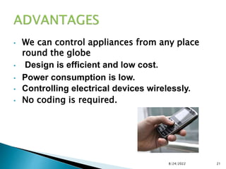
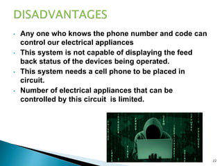
 SAYANTAN MAITRA
 SHYAMAL BANERJEE
 KRISHNENDRA BHATTACHARYYA
 CHANDRANI NAYAK
 ROLL-40,43,24,3058(LE)
 ECE-4th YEAR-KGEC
8/24/2022 1
 I hereby certify that the work which is being presented in the Minor project
entitled “DTMF BASED HOME APPLIANCE CONTROL” in partial fulfillment for
the award of the degree of B.Tech in ECE affiliated to MAKAUT and submitted
to the dept. of ECE of KGEC is an authentic record of my own work carried
out during a period from July 2015 to Dec.2015. The matter represented in
this report has not been submitted by me for award of any other degree of
this or any other institute.
 Dated :-8/24/2022
SAYANTAN MAITRA,SHYAMAL BANERJEE
KRISHNENDRA BHATTACHARYA,CHANDRANI NAYAK
This is to certify that the above statement made by the candidate is correct to
the best of our knowledge.
Date : I/c Minor Project Head-ECE
Examiner
8/24/2022 2
 It is indeed a great pleasure for us to express our gratitude
towards or mentor Shri Sandeep Nandi fro his priceless help
and moral support during the completion of project. We
would like to external our thanks to all the faculty members
for their valuable help during the project. We remember so
many students who participated actively in the teaching
learning process which, in effect, gave us tips and
suggestions on how this project should be. We thank them all
and place on record beyond mere superficially.
 SAYANTAN MAITRA
 SHYAMAL BANERJEE
 KRISHNENDRA BHATTACHARYYA
 CHANDRANI NAYAK
8/24/2022 3
 ABSTRACT 5
 INTRODUCTION 6
 OUR GOAL 7-14
 OUR PATHFLOW 15
 APPLICATIONS 16
 ADVANTAGES 17
 DISADVANTAGES 18
 OUR FUTURE PLANS AND
CONCLUSION 19
 REFERNCES 20
8/24/2022 4
 Traditionally electrical appliances in a home are
controlled via switches that regulate the electricity to
these devices. As the world gets more and more
technologically advanced, we find new technology
coming in deeper and deeper into our personal lives even
at home. Home automation is becoming more and more
popular around the world and is becoming a common
practice. The process of home automation works by
making everything in the house automatically controlled
using technology to control and do the jobs that we would
normally do manually. Home automation takes care of a
lot of different activities in the house.
this project we propose a unique System for Home
automation utilizing Dual Tone Multi Frequency (DTMF)
that is paired with a wireless module to provide seamless
wireless control over many devices in a house. The block
diagram is a shown below. This user console has many
keys , each corresponding to the device that needs to be
activated. The encoder encodes the user choice and sends
via a FM transmitter. The FM receiver receives the
modulated signal and demodulates it and the user choice
is determined by the DTMF decoder. Based upon this the
required appliance is triggered.
8/24/2022 5
 The aim of the proposed system is to develop a cost
effective
solution that will provide controlling of home
appliances
remotely and enable home security against intrusion
in the
absence of homeowner. The system provides
availability due to development of a low cost system.
The home appliances control system with an
affordable cost was thought to be built that should be
mobile providing remote access to the appliances and
allowing home security. Though devices connected as
home and office appliances consume electrical
power. These devices should be controlled as well as
turn on/off if required. Most of
the times it was done manually. Now it is a necessity
to control devices more effectively and efficiently at
anytime from anywhere.
8/24/2022 6
 REGULATED POWER SUPPLY
 DTMF DECODER IC(IC 8870)
 RESISTERS AND CAPACITOR
 CRYSTAL OSCILLATOR
 IC 7474 D FLIP FLOP
 BC 547 TRANSISTOR
 6 VOLT RELAY
8/24/2022 7
 OUR GOAL IS TO DESIGN SUCH A CIRCUIT SO
THAT WE CAN MAKE THE REAL CIRCUIT PROPERLY
WITHOUT ANY SIGNIFICANT VARIATION FROM THE
THEORTICAL PART AND WE CAN IMPLEMENT OUR
IDEAS IN OUR PROJECT ‘DTMF BASED HOME
APPLIANCE CONTROL’
 VARIOUS BLOCK DIAGRAMS AND COMPONENTS
FOR DESIGNING THE CIRCUITS ARE GIVEN
BELOW…….
8/24/2022 8
 BLOCK DIAGRAM
8/24/2022 9
Pin Function
Name Function Description
IN+,IN- Non-inverting, Inverting
input
Connection to front-end differential
amplifier
GS Gain select Access to output of OpAmp to
feedback connection
Vref Ref. o/p voltage(vdd/2) For biasing
INH Inhibits detection of tones Represents keys A,B,C,D
OSC3 Digital oscillator o/p
PD Power down Inhibits oscillator
OSC1,OSC2 Clk. i/p, Clk. o/p 3.57MHz crystal oscillator
Vss Negative power supply Normally connected to 0V.
TOE Three stage output enable High logic enables Q1-Q4
Q1,Q2,Q3,Q4 Three stage output Code corresponding to the last valid
tone pair received
StD , Est Delay , Early steering o/p Presents a logic high when a receive
tone pair has been reigstered
St/Gt Steering i/p, Guard time
output
St causes to register tone pair and G
causes to reset external steering.
Vdd, IC +ve power supply,Internal Must be tied to vss.
8/24/2022 10
8/24/2022 11
Button Low DTMF
Frequency
(Hz)
High DTMF
Frequency(
Hz)
Binary Coded Output
Q1 Q2 Q3 Q4
1 697 1209 0 0 0 1
2 697 1336 0 0 1 0
3 697 1477 0 0 1 1
4 770 1209 0 1 0 0
5 770 1336 0 1 0 1
6 770 1477 0 1 1 0
7 852 1209 0 1 1 1
8 852 1336 1 0 0 0
9 852 1477 1 0 0 1
0 941 1336 1 0 1 0
* 941 1209 1 0 1 1
# 941 1477 1 1 0 0
8/24/2022 12

The relay takes advantage of the fact that when electricity flows
through a coil, it becomes an electromagnet.
 The electromagnetic coil attracts a steel plate, which is attached to a
switch. So the switch's motion (ON and OFF) is controlled by the
current flowing to the coil.
 A very useful feature of a relay is that it can be used to electrically
isolate different parts of a circuit. It will allow a low voltage circuit
(e.g. 5VDC) to switch the power in a high voltage circuit (e.g. 100
VAC or more).
 The relay operates mechanically, so it can not operate at highspeed.
8/24/2022 13
8/24/2022 14
8/24/2022 15
 CIRCUIT DIAGRAM
8/24/2022 16
 The output Q4 from the DTMF decoder IC is fed to
the clock input of IC 7474 D flip flop which acts as a
buffer to the output from M8870 DTMF decoder IC.
 IC7474 is configured as Toggling mode, that is if it
gets a clock pulse the output of this IC (Pin 5) sets to
high and further clock pulse resets back the IC. (The
outputs toggle whenever a key is pressed).
 When we press and release any of the keys among 1,
3, 5, 7, 9 and *, the DTMF decoder IC generates a
high pulse which acts as a clock to our flip flop and
sets the output flip flop to high.
 The output of flip flop is connected to the relay driver
circuit via 100Ω resistor; this output energizes the
relay coil through BC547 transistor and turns ON the
bulb that is connected at the normally open terminal
of relay circuit.
8/24/2022 17
 Our project uses M-8870 DTMF decoder IC which decodes
tone generated by the keypad of cell phone.
 When you press any key on your mobile phone while call is
in progress, the other person will hear some tones
corresponding to the keys pressed. These tones are based
on the DTMF (Dual Tone Multi Frequency) technology.
 Data is transmitted as pairs of tones. The receiver detects
the valid frequency pair and gives the appropriate BCD
code as the output of the DTMF decoder IC.
 DTMF signal can be tapped directly from the microphone
pin of cell phone device.
 See the figure below. Cut the microphone wire and you will
be able to see 4 wires. Among these wires you need only 2
wires- Ground and Right as shown in figure.
 Select the right wire and connect it as the DTMF input to
the decoder circuit. Ground should be connected to
common ground of our circuit.
 The signals from the microphone wire are processed by
the DTMF decoder IC which generates the equivalent
binary sequence as a parallel output of Q1, Q2, Q3, and
Q4.
8/24/2022 18
• This system can be used in industrial applications.
• This system can be employed in houses ,where people often
forget to switch off electrical appliances
• This system can be used to control AC’s to set the room
temperature when we are outside
• We can extend this circuit to control many electrical
devices with some modifications using 4 x16 decoder IC.
8/24/2022 19
• Saves electricity (when we forget to switch off and
go out).
• Quick response is achieved.
• Construction is easy.
• Easy to maintain and repair.
• Comparatively the operation cost is less.
•
8/24/2022 20
• We can control appliances from any place
round the globe
• Design is efficient and low cost.
• Power consumption is low.
• Controlling electrical devices wirelessly.
• No coding is required.
8/24/2022 21
• Any one who knows the phone number and code can
control our electrical appliances
• This system is not capable of displaying the feed
back status of the devices being operated.
• This system needs a cell phone to be placed in
circuit.
• Number of electrical appliances that can be
controlled by this circuit is limited.
8/24/2022 22
 As we are at the beginning of our project we
will continue our project as to our next
semester where we will complete the
remaining works of the projects and will
submit the final report as per the
requirement………
8/24/2022 23
 http://www.atmel.com/devices/at89s52.aspx
 https://en.wikipedia.org/wiki/Dual-
tone_multi-frequency_signaling
 http://www.smerobot.org/08_scientific_pape
rs/papers/Calcagno_et-al_ISR-Robotik06.pdf
 http://www.datasheetdir.com/NATIONAL-
DM74LS373+Latches
 http://www.princeton.edu/~achaney/tmve/wi
ki100k/docs/Dual-tone_multi-
frequency.html
8/24/2022 24
8/24/2022 25

DTMFJOYHO.pptx

  • 1.
     SAYANTAN MAITRA SHYAMAL BANERJEE  KRISHNENDRA BHATTACHARYYA  CHANDRANI NAYAK  ROLL-40,43,24,3058(LE)  ECE-4th YEAR-KGEC 8/24/2022 1
  • 2.
     I herebycertify that the work which is being presented in the Minor project entitled “DTMF BASED HOME APPLIANCE CONTROL” in partial fulfillment for the award of the degree of B.Tech in ECE affiliated to MAKAUT and submitted to the dept. of ECE of KGEC is an authentic record of my own work carried out during a period from July 2015 to Dec.2015. The matter represented in this report has not been submitted by me for award of any other degree of this or any other institute.  Dated :-8/24/2022 SAYANTAN MAITRA,SHYAMAL BANERJEE KRISHNENDRA BHATTACHARYA,CHANDRANI NAYAK This is to certify that the above statement made by the candidate is correct to the best of our knowledge. Date : I/c Minor Project Head-ECE Examiner 8/24/2022 2
  • 3.
     It isindeed a great pleasure for us to express our gratitude towards or mentor Shri Sandeep Nandi fro his priceless help and moral support during the completion of project. We would like to external our thanks to all the faculty members for their valuable help during the project. We remember so many students who participated actively in the teaching learning process which, in effect, gave us tips and suggestions on how this project should be. We thank them all and place on record beyond mere superficially.  SAYANTAN MAITRA  SHYAMAL BANERJEE  KRISHNENDRA BHATTACHARYYA  CHANDRANI NAYAK 8/24/2022 3
  • 4.
     ABSTRACT 5 INTRODUCTION 6  OUR GOAL 7-14  OUR PATHFLOW 15  APPLICATIONS 16  ADVANTAGES 17  DISADVANTAGES 18  OUR FUTURE PLANS AND CONCLUSION 19  REFERNCES 20 8/24/2022 4
  • 5.
     Traditionally electricalappliances in a home are controlled via switches that regulate the electricity to these devices. As the world gets more and more technologically advanced, we find new technology coming in deeper and deeper into our personal lives even at home. Home automation is becoming more and more popular around the world and is becoming a common practice. The process of home automation works by making everything in the house automatically controlled using technology to control and do the jobs that we would normally do manually. Home automation takes care of a lot of different activities in the house. this project we propose a unique System for Home automation utilizing Dual Tone Multi Frequency (DTMF) that is paired with a wireless module to provide seamless wireless control over many devices in a house. The block diagram is a shown below. This user console has many keys , each corresponding to the device that needs to be activated. The encoder encodes the user choice and sends via a FM transmitter. The FM receiver receives the modulated signal and demodulates it and the user choice is determined by the DTMF decoder. Based upon this the required appliance is triggered. 8/24/2022 5
  • 6.
     The aimof the proposed system is to develop a cost effective solution that will provide controlling of home appliances remotely and enable home security against intrusion in the absence of homeowner. The system provides availability due to development of a low cost system. The home appliances control system with an affordable cost was thought to be built that should be mobile providing remote access to the appliances and allowing home security. Though devices connected as home and office appliances consume electrical power. These devices should be controlled as well as turn on/off if required. Most of the times it was done manually. Now it is a necessity to control devices more effectively and efficiently at anytime from anywhere. 8/24/2022 6
  • 7.
     REGULATED POWERSUPPLY  DTMF DECODER IC(IC 8870)  RESISTERS AND CAPACITOR  CRYSTAL OSCILLATOR  IC 7474 D FLIP FLOP  BC 547 TRANSISTOR  6 VOLT RELAY 8/24/2022 7
  • 8.
     OUR GOALIS TO DESIGN SUCH A CIRCUIT SO THAT WE CAN MAKE THE REAL CIRCUIT PROPERLY WITHOUT ANY SIGNIFICANT VARIATION FROM THE THEORTICAL PART AND WE CAN IMPLEMENT OUR IDEAS IN OUR PROJECT ‘DTMF BASED HOME APPLIANCE CONTROL’  VARIOUS BLOCK DIAGRAMS AND COMPONENTS FOR DESIGNING THE CIRCUITS ARE GIVEN BELOW……. 8/24/2022 8
  • 9.
  • 10.
    Pin Function Name FunctionDescription IN+,IN- Non-inverting, Inverting input Connection to front-end differential amplifier GS Gain select Access to output of OpAmp to feedback connection Vref Ref. o/p voltage(vdd/2) For biasing INH Inhibits detection of tones Represents keys A,B,C,D OSC3 Digital oscillator o/p PD Power down Inhibits oscillator OSC1,OSC2 Clk. i/p, Clk. o/p 3.57MHz crystal oscillator Vss Negative power supply Normally connected to 0V. TOE Three stage output enable High logic enables Q1-Q4 Q1,Q2,Q3,Q4 Three stage output Code corresponding to the last valid tone pair received StD , Est Delay , Early steering o/p Presents a logic high when a receive tone pair has been reigstered St/Gt Steering i/p, Guard time output St causes to register tone pair and G causes to reset external steering. Vdd, IC +ve power supply,Internal Must be tied to vss. 8/24/2022 10
  • 11.
  • 12.
    Button Low DTMF Frequency (Hz) HighDTMF Frequency( Hz) Binary Coded Output Q1 Q2 Q3 Q4 1 697 1209 0 0 0 1 2 697 1336 0 0 1 0 3 697 1477 0 0 1 1 4 770 1209 0 1 0 0 5 770 1336 0 1 0 1 6 770 1477 0 1 1 0 7 852 1209 0 1 1 1 8 852 1336 1 0 0 0 9 852 1477 1 0 0 1 0 941 1336 1 0 1 0 * 941 1209 1 0 1 1 # 941 1477 1 1 0 0 8/24/2022 12
  • 13.
     The relay takesadvantage of the fact that when electricity flows through a coil, it becomes an electromagnet.  The electromagnetic coil attracts a steel plate, which is attached to a switch. So the switch's motion (ON and OFF) is controlled by the current flowing to the coil.  A very useful feature of a relay is that it can be used to electrically isolate different parts of a circuit. It will allow a low voltage circuit (e.g. 5VDC) to switch the power in a high voltage circuit (e.g. 100 VAC or more).  The relay operates mechanically, so it can not operate at highspeed. 8/24/2022 13
  • 14.
  • 15.
  • 16.
  • 17.
     The outputQ4 from the DTMF decoder IC is fed to the clock input of IC 7474 D flip flop which acts as a buffer to the output from M8870 DTMF decoder IC.  IC7474 is configured as Toggling mode, that is if it gets a clock pulse the output of this IC (Pin 5) sets to high and further clock pulse resets back the IC. (The outputs toggle whenever a key is pressed).  When we press and release any of the keys among 1, 3, 5, 7, 9 and *, the DTMF decoder IC generates a high pulse which acts as a clock to our flip flop and sets the output flip flop to high.  The output of flip flop is connected to the relay driver circuit via 100Ω resistor; this output energizes the relay coil through BC547 transistor and turns ON the bulb that is connected at the normally open terminal of relay circuit. 8/24/2022 17
  • 18.
     Our projectuses M-8870 DTMF decoder IC which decodes tone generated by the keypad of cell phone.  When you press any key on your mobile phone while call is in progress, the other person will hear some tones corresponding to the keys pressed. These tones are based on the DTMF (Dual Tone Multi Frequency) technology.  Data is transmitted as pairs of tones. The receiver detects the valid frequency pair and gives the appropriate BCD code as the output of the DTMF decoder IC.  DTMF signal can be tapped directly from the microphone pin of cell phone device.  See the figure below. Cut the microphone wire and you will be able to see 4 wires. Among these wires you need only 2 wires- Ground and Right as shown in figure.  Select the right wire and connect it as the DTMF input to the decoder circuit. Ground should be connected to common ground of our circuit.  The signals from the microphone wire are processed by the DTMF decoder IC which generates the equivalent binary sequence as a parallel output of Q1, Q2, Q3, and Q4. 8/24/2022 18
  • 19.
    • This systemcan be used in industrial applications. • This system can be employed in houses ,where people often forget to switch off electrical appliances • This system can be used to control AC’s to set the room temperature when we are outside • We can extend this circuit to control many electrical devices with some modifications using 4 x16 decoder IC. 8/24/2022 19
  • 20.
    • Saves electricity(when we forget to switch off and go out). • Quick response is achieved. • Construction is easy. • Easy to maintain and repair. • Comparatively the operation cost is less. • 8/24/2022 20
  • 21.
    • We cancontrol appliances from any place round the globe • Design is efficient and low cost. • Power consumption is low. • Controlling electrical devices wirelessly. • No coding is required. 8/24/2022 21
  • 22.
    • Any onewho knows the phone number and code can control our electrical appliances • This system is not capable of displaying the feed back status of the devices being operated. • This system needs a cell phone to be placed in circuit. • Number of electrical appliances that can be controlled by this circuit is limited. 8/24/2022 22
  • 23.
     As weare at the beginning of our project we will continue our project as to our next semester where we will complete the remaining works of the projects and will submit the final report as per the requirement……… 8/24/2022 23
  • 24.
     http://www.atmel.com/devices/at89s52.aspx  https://en.wikipedia.org/wiki/Dual- tone_multi-frequency_signaling http://www.smerobot.org/08_scientific_pape rs/papers/Calcagno_et-al_ISR-Robotik06.pdf  http://www.datasheetdir.com/NATIONAL- DM74LS373+Latches  http://www.princeton.edu/~achaney/tmve/wi ki100k/docs/Dual-tone_multi- frequency.html 8/24/2022 24
  • 25.