Download as PDF, PPTX


![Intensity Transformations
The spatial domain processes can be denoted by the expression
g(x, y) = T[f (x, y)]
where f (x, y) is the input image and g(x, y) is the output image
M K Kar (BCET) Digital Image Processing July 12, 2020 10 / 26](https://image.slidesharecdn.com/presentation1-200714110922/75/Presentation-1-10-2048.jpg)
![Image Negatives
The negative of an image with intensity levels in the range [0, L − 1]
is obtained by using the negative transformation, given by the
expression s = (L − 1) − r.
Figure: image negetive
M K Kar (BCET) Digital Image Processing July 12, 2020 11 / 26](https://image.slidesharecdn.com/presentation1-200714110922/75/Presentation-1-11-2048.jpg)


![Image Histogram
The histogram of a digital image with intensity levels in the range
[0,L-1] is a discrete function h(rk) = nk, where rk is the kth intensity
value and nkis the number of pixels in the image with intensity rk.
M K Kar (BCET) Digital Image Processing July 12, 2020 15 / 26](https://image.slidesharecdn.com/presentation1-200714110922/75/Presentation-1-15-2048.jpg)
![Histogram Equalization
The histogram equalization of a digital image with intensity levels in
the range [0, L − 1] is a discrete function sk = T(rk), where rk is the
kth intensity value and nkis the number of pixels in the image with
intensity rk is.
sk = T(rk) = (L − 1)
k
j=0
pr (rj ) =
(L − 1)
MN
k
j=0
(nj )
M K Kar (BCET) Digital Image Processing July 12, 2020 16 / 26](https://image.slidesharecdn.com/presentation1-200714110922/75/Presentation-1-16-2048.jpg)


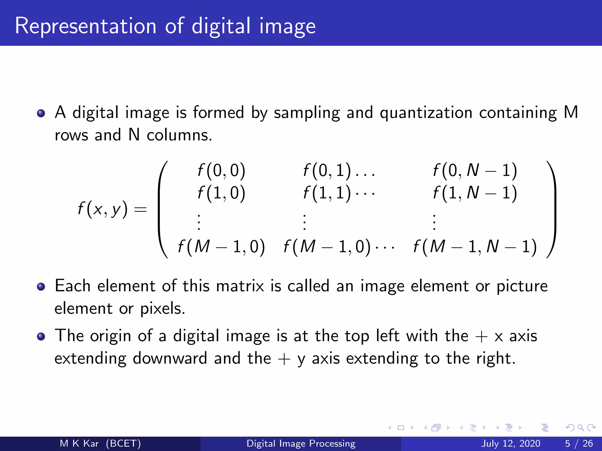
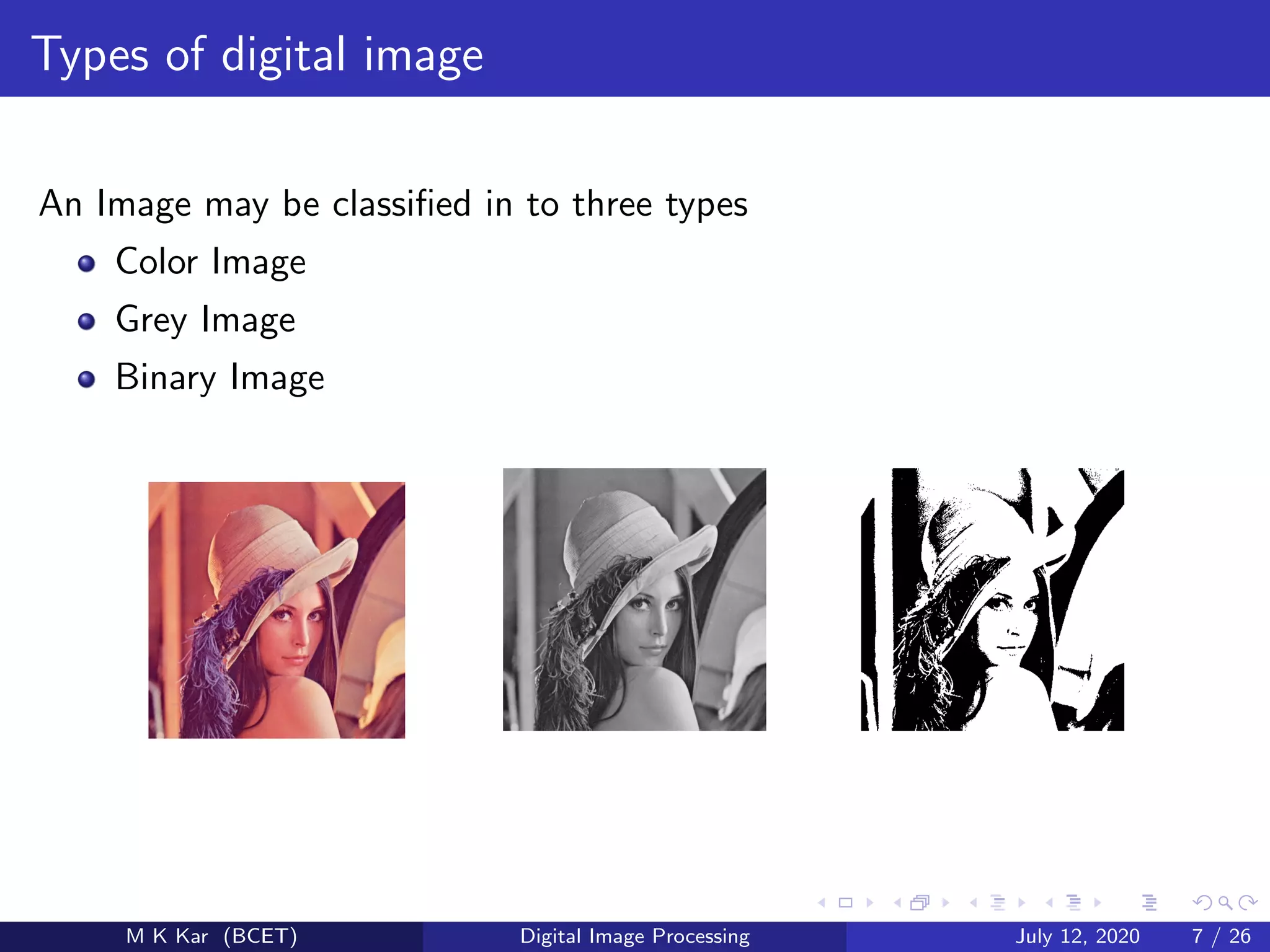
The document discusses digital image processing and is presented by M K Kar of Balasore College of Engineering and Technology. It covers fundamentals of digital image processing including representation of digital images, intensity transformations, spatial filtering, frequency domain representation, and applications in medicine, agriculture, industry and more. Transformation techniques like contrast stretching and histogram equalization are described. Spatial filters like averaging, median and Laplacian filters are covered along with sharpening and smoothing effects.


![[PDF] Automatic Image Co-segmentation Using Geometric Mean Saliency (Top 10% ...](https://cdn.slidesharecdn.com/ss_thumbnails/gmsicip-150218012406-conversion-gate01-thumbnail.jpg?width=640&height=640&fit=bounds)


