Contents:
1.history
2.what is precast concrete and why it is called so?
3.properties
4.features
5.precast concrete structural elements
6.types
7.advantages
8.disadvantages
Running Head BRIDGE DESIGN1BRIDGE DESIGN31.docxtoddr4
Running Head: BRIDGE DESIGN 1
BRIDGE DESIGN 31
Title:
Student Name:
Institution:
Course:
Date:
BRIDGE DESIGN FOR THE MOTOR WAY BELOW
8m
Embankment
A
Motorway
16m
10m
Central Reservation
Motorway
16m
Grass Verge
Existing Factory Units
Footway
A
Carriagewaym
Existing Factory Units
Fixed Factory Entrance
Fixed Factory Entrance
3m
2m
3m
2m
10mm
Existing Highway to Proposed Bridge
Existing Development
Proposed Development
Existing Development
Existing Retaining Wall – 500mm thick rc construction indicated by old record drawings
Central Reservation
10m
10m
Section A-A
2m footway
1.2m high parapets
10m carriageway
Bridge Deck Section
Figure 1
Bridge design
Most suitable bridge forms
· Beam bridge
· Arch bridge
The beam bridge: Beam and slab with ladder decks
This form of bridges comprises of slab which sits on top of steel I-beams. This form is mostly used for mid span highway bridge which is where our required bridge falls in.
Slab in this system is supported on tow main girders with a spacing of about 3.5m and it lies longitudinally between the girders as per the below diagram.
Figure 1
The bridge will use plate girders giving us a scope to vary the flange and web sizes to fit and suit the bridge load carrying capabilities. In the design process, ability of the bridge to carry the maximum load expected and the loading at the various stages of construction will guide on the proportion of girders that is their depth, width of tension and compression flanges and web thickness.
The girders are erected firmly on the ground and have stud connectors welded on the top flange to provide composite action between the slab and girder. The number of studs and spacing vary depending on expected level of shear flow between steel girder and concrete slab.
The girders rest on bearings fastened to the bottom flange. The girders are stiffened to carry the bearing loads at these points. Some cases apply bracing between the girders at support to carry lateral forces and provide torsional restraint.
Bridge description
· The bridge will have a span of 50m.
· The bridge will be raised to a height of 10m on both sides to be in level with the existing highway. The girders will have constant height.
· The bridge cross section will have the reinforced concrete slab sitting on top of two main abutment substructures and an extra substructure which will be on the central reservation. The main substructure will be located at the embarkment of the road.
Construction sequence
Abutment substructure construction
Girder construction
The bridge will consist of two main girder I beams. The girders will be of the same height. To make the I-beam, steel plates will be used. The steel plate is cut into the required sizes for the bottom flange and top flange and for the web. The cut pieces are then fillet welded into the I-section. This is done either by machine manual assembling in jig or through improved pressing machine .
A short and elaborate Case Study on High Rise Buildings for the course of Advanced Building Construction from students of 8th Semester Architecture at VNIT, Nagpur (January- April 2017)
This slide explains different structural systems used in high rise buildings.what is the true meaning of high rise building ?
aims of high rise? objectives of high rise?
Information over different types of Formworks, RMC, Reinforcements and cement types used in the process of Speedy Construction.one way two way slab & waffle slab.
Conventional Indian construction industry has been forced to look for technology to address its demand & supply gap, diminishing skilled labour and stringent time frame.
Precast concrete construction methodology fits perfectly as an alternative for traditional construction with shorter construction duration and reduction in labor, while exceeding quality standards of conventional construction practices in India.
The success of this technology fully depends on the Architects, the Structural engineers and the Execution team who are willing to adapt this change from convention method of construction to the precast construction. Change gives us a lot of opportunity to adapt, innovate and implement new efficient technology which will be beneficial to the society at large margin.
This technology is becoming trend due to its huge advantages. But in recent past hazards attended to such construction due to collapse. So from the Structural Engineering point of view we have to design keeping in mind the structural safety against this type of collapse.
After viewing this program, you will be able to:
• Identify the difference between precast/pre-stressed concrete and tilt up concrete structures
• Explain the benefits of using tilt up concrete
• Discuss the design considerations for tilt up concrete structures
• BIM into precast / Tilt up concrete
Hello everyone! I am thrilled to present my latest portfolio on LinkedIn, marking the culmination of my architectural journey thus far. Over the span of five years, I've been fortunate to acquire a wealth of knowledge under the guidance of esteemed professors and industry mentors. From rigorous academic pursuits to practical engagements, each experience has contributed to my growth and refinement as an architecture student. This portfolio not only showcases my projects but also underscores my attention to detail and to innovative architecture as a profession.
Between Filth and Fortune- Urban Cattle Foraging Realities by Devi S Nair, An...Mansi Shah
This study examines cattle rearing in urban and rural settings, focusing on milk production and consumption. By exploring a case in Ahmedabad, it highlights the challenges and processes in dairy farming across different environments, emphasising the need for sustainable practices and the essential role of milk in daily consumption.
You could be a professional graphic designer and still make mistakes. There is always the possibility of human error. On the other hand if you’re not a designer, the chances of making some common graphic design mistakes are even higher. Because you don’t know what you don’t know. That’s where this blog comes in. To make your job easier and help you create better designs, we have put together a list of common graphic design mistakes that you need to avoid.
White wonder, Work developed by Eva TschoppMansi Shah
White Wonder by Eva Tschopp
A tale about our culture around the use of fertilizers and pesticides visiting small farms around Ahmedabad in Matar and Shilaj.
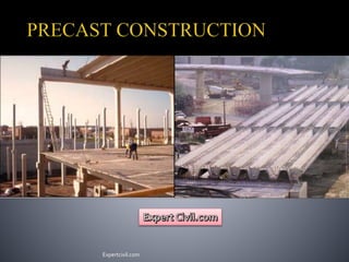
2. Precast Concrete is a construction product
produced by casting concrete in a reusable
mold or "form" which is then cured in a
controlled environment, transported to the
construction site and lifted into place. In
contrast, standard concrete is poured into
site-specific forms and cured on site.
also known as "prefabricated“
produced in plants in a location away from
the construction site
These components are manufactured by
industrial methods based on mass
production in order to build a large number
of buildings in a short time at low cost.
Expertcivil.com
3. Precast concrete building
components and site amenities
Earth retaining systems
Sanitary and Storm water
management products
Precast concrete transportation
products
Marine Products
Pre-stressed / Structural Products
Expertcivil.com
4. Concrete is cast off site
Identical forms can used several times
Batter quality control
Control on curing
Un affected by weather , when casting
Construction in less time
Less cost
Waste materials can be used
( fly ash)
Fire resistant
Can avoid air born pollution on site
( dusting )
Expertcivil.com
5. Costlier for small projects
Required skilled workers
Transportation is costly of large members for
small projects.
It’s required to be design and detailed for
transportation, erection.
Required different site for its production
Expertcivil.com
6. A whole building can be construct.
Precast beams, columns, footings,
floors, roofs, walls and stairs
Erection on site with care
Depending on the load-bearing
structure, Precast buildings by former
Soviet Union and Eastern European
countries can be divided into the
following categories:
· Large-panel systems
· Frame systems
· Slab-column systems
Expertcivil.com
7. "large-panel system“ composed of large
wall and floor concrete panels connected
in the vertical and horizontal.
Panels form a box-like structure .
Both vertical and horizontal panels resist
gravity load.
Wall panels are usually one story high.
Horizontal floor and roof panels span
either as one-way or two-way slabs.
When properly joined together, these
horizontal elements act as diaphragms
that transfer the lateral loads to the walls.
Expertcivil.com
10. Precast frames can be constructed using either linear elements or spatial beam-column
sub-assemblages.
The connecting faces are at the beam-column junctions.
The beams can be seated on corbels at the columns, for ease of construction.
To aid the shear transfer from the beam to the column. The beam-column joints
accomplished in this way are hinged.
However, rigid beam-column connections are used in some cases, when the continuity
of longitudinal reinforcement through the beam-column joint needs to be ensured.
Expertcivil.com
16. These systems rely on shear walls to sustain lateral load effects, whereas the slab-
column structure resists mainly gravity loads.
Pre-stressed slab-column system were introduced in the last decade of the Soviet
Union (period 1980)
Reinforced concrete slabs are poured on the ground in forms.
The slab panels are lifted to the top of the column and then moved downwards to the
final position. Temporary supports are used to keep the slabs in the position until the
connection with the columns has been achieved.
In the connections, the steel bars (dowels) that project from the edges of the slabs are
welded to the dowels of the adjacent components and transverse reinforcement bars
are installed in place. The connections are then filled with concrete that is poured at
the site.
Most buildings of this type have some kind of lateral load-resisting elements, mainly
consisting of cast-in-place or precast shear walls
Expertcivil.com
18. Good formwork to be used
Lubricant should be applied to forms
Quality concrete to be used
Suitable method of vibration should be used
Water for Curing should be good
Steam curing can be use for mass production, if cost is available
Expertcivil.com
19. Once a piece has been fabricated, it is
necessary to remove it from the mold without
being damaged.
Breakaway forms should be used to allow a
member to lift away from the casting bed
without becoming wedged within the form
Orientation of members during storage,
shipping and final in-place position is critical
Sand bed will help protect edge
Tilt tables or turning rigs are used to reduce
stripping stresses
Warpage in storage may be caused by
temperature or shrinkage differential
between surfaces
creep
The member should be oriented in the yard so
that the sun does not overheat one side
Expertcivil.com
20. The loads and forces on precast and
pre-stressed concrete members
during production, transportation or
erection will frequently require a
separate analysis
Support points and orientation are
usually different from members in
their final position
it may be necessary to cast in extra
lifting devices to facilitate these
maneuvers.
The number and location of lifting
devices are chosen to keep stresses
within the allowable limits
special handling required by the
design should be clearly shown on
drawings
Expertcivil.com
21. Lifting points must be located to keep
member stresses within limits and to ensure
proper alignment of the piece as it is being
lifted
Members with unsymmetrical geometry or
projecting sections may require
supplemental lifting points to achieve even
support during handling
“Come-alongs” or “chain-falls” are
frequently used for these auxiliary lines
When the member has areas of small cross
section or large cantilevers, it may be
necessary to add a structural steel “strong
back” to the piece to provide added strength
temporary loads
Expertcivil.com
22. Columns with eccentric loads from other
framing members produce side-sway which
means the columns lean out of plumb
A similar condition can exist when cladding
panels are erected on one
side of a multistory structure
Unbalanced loads due to partially complete
erection may result in beam rotation
The erection drawings should address these
Conditions
Some solutions are:
Install wood wedges between flange of tee
and top of beam,
Use connection to columns that prevent
rotation,
Erect tees on both sides of beam
Expertcivil.com
23. Rotations and deflections of framing
members may be caused by cladding
panels. This may result in alignment
problems and require connections that
allow for alignment adjustment after
all panels are erected
Careful planning of the erection
sequence is important
Expertcivil.com
24. The project can be economical, considering the following factors:
Stability and stresses on the element during handling
Transportation size and weight regulations and equipment restrictions
Available crane capacity at both the plant and the project site.
Position of the crane must be considered, since capacity is a function of reach
Storage space, truck turning radius, and other site restrictions
Expertcivil.com
25. Koshland Integrated Natural Science
Center
Located on the Haverford College campus
4-story laboratory facility with basement
Also contains classrooms, offices, &
communal spaces
Total area 185,423 ft2
Total project cost of $42.6 Million
Construction was done in phases
The work was completed in 6 months
Expertcivil.com
26. Superstructure – Precast concrete framing
Precast beams : 24”x12” spanning 21’
Precast columns : 16”x16” & 20”x20”
Foundation – (concrete masonry unit) CMU foundation/retaining walls, precast piers
Floor System – 10” precast plank with 2” topping
Façade – Stone & precast panels
Roof System – Steel framing with metal deck; precast plank
Typical story height of 13’
Expertcivil.com
31. Bridge can also construct with
precast.
Parts of a bridge, Substructures and
superstructures
In India growth of precast in bridge
is slow
But, Precast is growing continues
very rapidly in other countries, not
only for bridges in the short span
range, but also for spans in excess
of 45 meters.
Based on type of bridge and site
condition method of construction is
to be adopted.
Expertcivil.com
33. Prestressed concrete bridges are usually lower in first cost than all other types of
bridges.
With savings in maintenance, precast bridges offer maximum economy.
Every operation in the manufacturing process provides a point of inspection and
control over quality
Faster construction
Formwork of the superstructure can be eliminate
Piers, Abutments and wing walls can be made of precast concrete pieces quickly
assembled on the field.
Precast concrete bridges can be installed during all seasons
The durability of precast prestressed concrete bridge is good and the resulting low
maintenance requirements.
No painting is needed.
Superstructure can be made as shallow as possible in order to provide maximum
clearance with good structural designing
Greater fire resistance and design aesthetic is another advantage.
Expertcivil.com
34. T-Beam deck slab bridge
Simplest type of Precast bridge, most
of the bridges in India are of this type
Sub- structure is cast in situ
In superstructure, Main girders are
precast post tensioned, casted away
from site and are transported to site.
Secondary girders and Deck slab are
casted on Precast post tensioned
girders on site or precast slab can be
used.
Expertcivil.com
35. Post tensioning technique is to be used
in girders
In post tensioning, the concrete units
are casted bye incorporating duct to
house the tendons, when concrete
attains sufficient strength, high-tension
wires are tensioned bye means of
jacks, after then the duct is grouted.
Forces are transmitted to the concrete
at the end anchorage
Expertcivil.com
47. During designing all the loads are to
considered and losses are also to be
considered as per IS1343 for pre-
stressed concrete.
Casting and curing is to be done
properly for quality concrete. Suitable
method of post tensioning is to be
adopted.
Casted elements are to be stoked care
fully, details should be given by
designer
for storing members.
Transportation is to be done carefully to
avoid damage to the precast elements.
Erection process is to be well decided
and planed based on type of bridge and
site condition.
Expertcivil.com
48. Hangzhou Bay Bridge
Longest trans-oceanic highway bridge in the world, with a cable-stayed portion
across Hangzhou bay in the eastern coastal region of China (6-lanes)
Total length of bridge is 35.67mt.
Construction of the bridge was completed on June 14, 2007.
The bridge shortened the highway travel distance between Ningbo and Shanghai
from 400 km to 280 km and reduced travel time from 4 to 2.5 hours.
40 piers with large number of girders
Girder is of 70m length and 16.5m wide in plan
830 cubic meter of concrete for one girder and took 8 hours to cast one girder
Barge crane was used for erection of girders for 25 km. and for other portion
special machine was built
Expertcivil.com
54. Director - Martin P. Korn, President - Douglas ConeInitially, PCI, 1954
John Diaz & Ron Tola, Professor Parfitt – Thesis Advisor, Haverford College
Book, N. Krishna Raju, “Prestressed Concrete”, McGraw-Hill, 2008
Book, Rangwala, ”Bridge Engineering”, Charotar, 2010
Internet , “Google”,– Images
Internet, “Youtude”,- Videos
Expertcivil.com