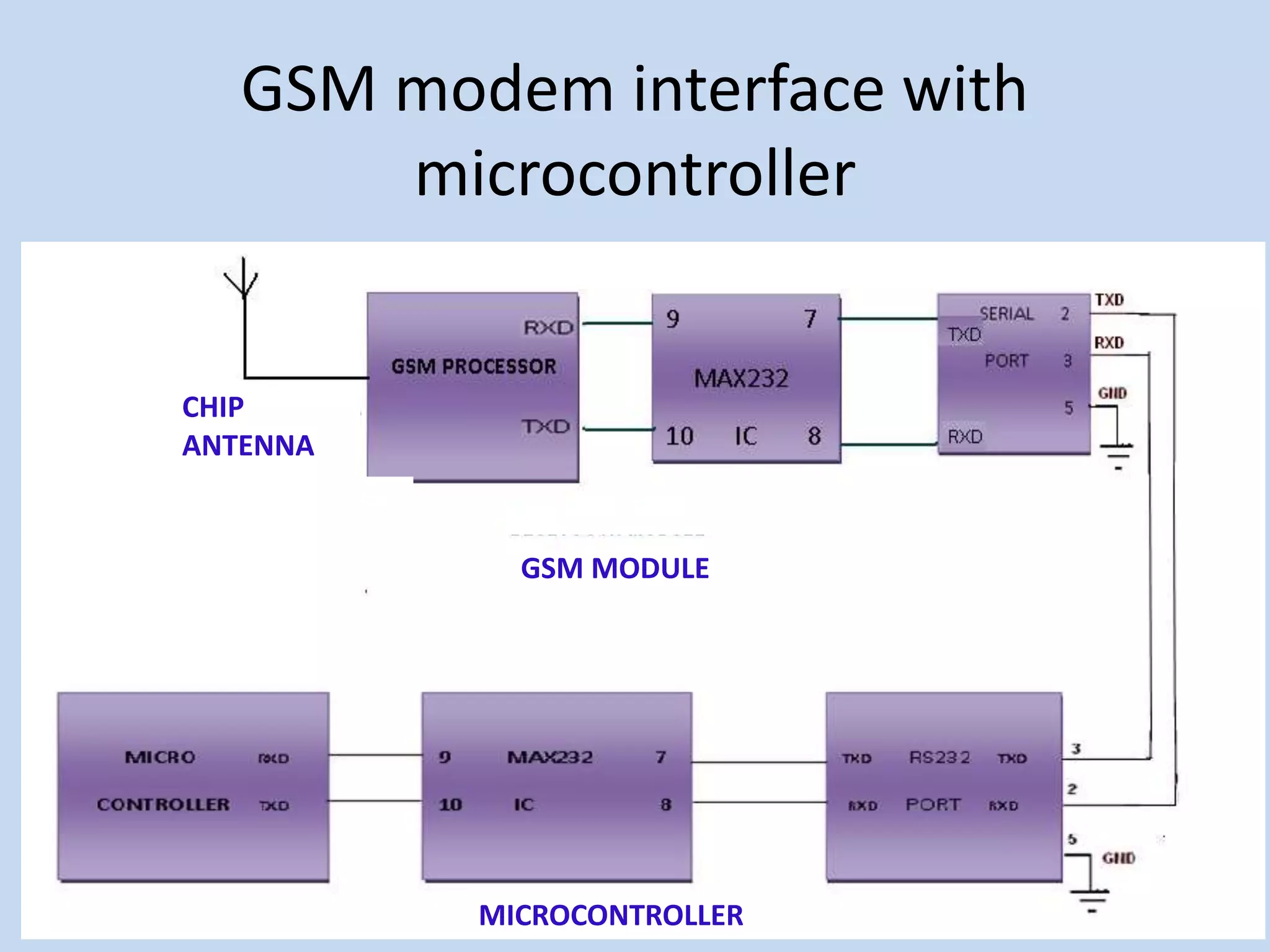
INTRODUCTION
Power utilities in different countries especially in the developing ones
are incurring huge losses due to electricity theft. To overcome this, a smart energy
metering system is employed to control electricity theft. In this system a smart
energy meter is installed in every consumer unit and a server is maintained at the
service provider side. Both the meter and the server are equipped with GSM
module which facilitates bidirectional communication between the two ends using
the existing GSM infrastructure.
Facilities to control meter bypassing and tampering are present. The
bidirectional GSM communication using SMS ensures the effectiveness of these
facilities. Pilferage of electricity can be substantially reduced by incorporating the
proposed measures along with the prepaid metering scheme, which is optional.
Consumers can easily recharge their energy meter by sending a PIN number
hidden in a scratch card to the server using SMS. Legal actions against dishonest
consumers can also be taken in this system
EXISTING PROJECT
Link method of on-spot monitoring facility:
It is a series link method which is used between standard electric energy meter and the user’s
single phase electric energy meter. Standard electricity measure module is connected in series
between the user single-phase electric energy meter and fire wire, zero wire of enter user, the
output of standard electricity measure module and the user’s single phase electric energy
meter are separately photoelectric isolated, then outputted to the microcontroller to measure
electricity
Electricity-stealing defense principle of link method facility:
Circuital voltage and current are monitored by standard electricity
measure module in real time. When loaded by using electricity, standard
electricity measure module outputs impulse which has a proportional
relationship with power (the number of output impulse per kilowatt), the
output of user single phase electric energy meter also has a proportional
relationship with power.
If electricity stealing is took place, the user single phase electric
energy meter cannot measure accurately, then discrepancies will come up
between the number of output impulse in standard electricity measure
module and user single-phase electric energy meter in unit time, it is
considered electricity-stealing happen or user electric energy abnormal when
the discrepancies accumulative total arrives certain level.
PROJECT DESCRIPTION
In our project the power utility maintains a server and each consumer is
provided an energy meter. The server and energy meters use GSM modem and
GSM module respectively to communicate with each other using the GSM network.
This project is designed for power theft prevention. First we measure the output
power of EB station and send this power level to the microcontroller through signal
conditioner. Mainly power theft occurs in the middle of the two distribution
systems. Each distribution output power level is sensed and sent to the
microcontroller through signal conditioner. If both the power levels are equal,
there is no power theft but if the power level is unequal power theft has occurred in
the transmission line.
When we detect the unequal power level of transmission line, the
microcontroller is connected to the alarm. If power theft occurs then the controller
sends the information through GSM. To receive the SMS and alert to the EB
persons and take immediate action to drop the power theft. And also in this project
the EB meter reading that is Unit and amount through sensing unit(Digital energy
meter) and Update Mobile.
BLOCK DIAGRAM
OUR MODULE
P89C51RD2BN
Microcontroller
Blocks of 89c51
PSEN-
PSEN
29ALE
30
VCC
40
EA
31
X1
19
X2
18
RST
9
P0.0/AD0
39
P0.1/AD1
38
P0.2/AD2
37
P0.3/AD3
36
P0.4/AD4
35
P0.5/AD5
34
P0.6/AD6
33
P0.7/AD7
32
P1.0
1
P1.1
2
P1.2
3
P1.3
4
P1.4
5
P1.5
6
P1.6
7
P1.7
8
P2.0/A8
21
P2.1/A9
22
P2.2/A10
23
P2.3/A11
24
P2.4/A12
25
P2.5/A13
26
P2.6/A14
27
P2.7/A15
28
P3.0/RXD
10
P3.1/TXD
11
P3.2/INT0
12
P3.3/INT1
13
P3.4/T0
14
P3.5/T1
15
P3.6/WR
16
P3.7/RD
17
U1
89C51
1
2
3
4
5
6
7
8
9
10
11
12
13
14
15
16
LCD
5
4
3
2
1
6
7
8
9
Connector DB9
VCC
10K POT
VCC
VCC
P1.1
P1.0
P2.6
P2.5
P2.4
P2.3
P2.2
P2.1
P2.0
P1.2
P2.7
CTS
P3.2
P3.3
20
VCC
P3.4
R1OUT
12
T1OUT
14
T2OUT
7
T2IN
10
T1IN
11
GND
15
VCC
16
R1IN
13
R2IN
8
R2OUT
9
C1+
1
C1-
3
C2+
4
C2-
5
V+
2
V-
6
ICL232
P3.5
P3.6
RST
P3.7
0.1MF
P0.0
0.1MF
ALE
P0.1
PSEN-
P0.2
P0.4
RTS
P0.3
P0.5
P0.6
CTS
RTS
P0.7
P1.3
P1.4
P1.5
P1.6
P1.7
11.0592MHz
0.1MF
0.1MF
RXD
RXD
TXD
TXD
VCC
1
2
3
Tiny Switch
33pF
33pF
P89C51RD2BN
ENERGY METER
Electronic Energy Meter
Electronic meters display the energy used on an LCD or LED or cyclometer display, and
some can also transmit readings to remote places. In addition to measuring energy used, electronic
meters can also record other parameters of the load and supply such as instantaneous and maximum
rate of usage demands, voltages, power factor and reactive power used etc. They can also support
time-of-day billing, for example, recording the amount of energy used during on-peak and off-peak
hours. Electric utilities use electric meters installed at customers premises to measure electric energy
delivered to their customers for billing purposes. They are typically calibrated in billing units, the
most common one being the kilowatt hour [kWh]. They are usually read once each billing period.
In settings when energy savings during certain periods are desired, meters may measure
demand, the maximum use of power in some interval. "Time of day" metering allows electric rates to
be changed during a day, to record usage during peak high-cost periods and off-peak, lower-cost,
periods. Also, in some areas meters have relays for demand response load shedding during peak load
periods.
GSM
GSM is an open, digital cellular technology used for transmitting
mobile voice and data services. GSM differs from first generation wireless
systems in that it uses digital technology and time division multiple access
transmission methods. GSM is a circuit-switched system that divides each
200kHz channel into eight 25kHz time-slots. GSM operates in the
900MHz.
GSM (Global System for Mobile communications) is the
technology that underpins most of the world's mobile phone networks.
The GSM platform is a hugely successful wireless technology and an
unprecedented story of global achievement and cooperation. GSM has
become the world's fastest growing communications technology of all
time and the leading global mobile standard, spanning 210 countries.
GSM
Operating frequency
Standard Bandwidth Used
• Asia & Europe : - 900MHz-1800MHz
• America : - 850MHz-1800MHz
• India (900MHz/1800MHz)
GSM INTERFACED WITH
MICROCONTROLLER
GSM modem interface with
microcontroller
GSM MODULE
CHIP
ANTENNA
MICROCONTROLLER
GSM Pin Diagram
Commands used in GSM:
Commands always start with AT (which means ATtention) and finish with
a <commands> character.
Commands Details
AT To initialize
ATD mob.no; To call
ATA To attend the call
ATH To hang the call
AT+CMGF=1 To set frame
AT+CMGS=“mob no” To send msg edit the mob no.
AT+CMGD=1 To delete the first msg
AT+CMGR=1 To read the first msg.
RS 232 DRIVER CIRCUIT
A standard serial interfacing for PC, RS232C, requires negative logic, i.e., logic '1' is -3V to -
12V and logic '0' is +3V to +12V. To convert a TTL logic, say, TxD and RxD pins of the uC
chips, thus need a converter chip. A MAX232 chip has long been using in many uC boards. It
provides 2-channel RS232C port and requires external 10uF capacitors.
RS232 DRIVER CIRCUIT
Pin Diagram :
1
2
3
4
5
6
7
8
16
15
14
13
12
11
10
9
C1+
V
S+
C1−
C2+
C2−
V
S−
T2OUT
R2IN
V
CC
GND
T1OUT
R1IN
R1OUT
T1IN
T2IN
R2OUT
Voltage levels:
Compilers
There are various C compilers are available in the market for each processor
families. For MCS-51 series the famous compilers are:
RIDE-51 from Raisonance
KEIL-51 from Keil
IAR-51 from IAR Compilers
PHYTHON
Here we use RIDE-51 for 89c51.
The programming in high-level language like embedded C, Embedded Linux will be
converted to hex code with the help of these compilers.
RIDE51 Sample program
Contd…
Downloader
• Flash Magic is a PC tool for programming flash based
microcontrollers from NXP using a serial or Ethernet protocol
while in the target hardware.
• It was created for Windows byEmbedded Systems Academy,
Inc..
Downloading…
THANK YOU!!

Electricity theft control

  • 1.
    INTRODUCTION Power utilities indifferent countries especially in the developing ones are incurring huge losses due to electricity theft. To overcome this, a smart energy metering system is employed to control electricity theft. In this system a smart energy meter is installed in every consumer unit and a server is maintained at the service provider side. Both the meter and the server are equipped with GSM module which facilitates bidirectional communication between the two ends using the existing GSM infrastructure. Facilities to control meter bypassing and tampering are present. The bidirectional GSM communication using SMS ensures the effectiveness of these facilities. Pilferage of electricity can be substantially reduced by incorporating the proposed measures along with the prepaid metering scheme, which is optional. Consumers can easily recharge their energy meter by sending a PIN number hidden in a scratch card to the server using SMS. Legal actions against dishonest consumers can also be taken in this system
  • 2.
    EXISTING PROJECT Link methodof on-spot monitoring facility: It is a series link method which is used between standard electric energy meter and the user’s single phase electric energy meter. Standard electricity measure module is connected in series between the user single-phase electric energy meter and fire wire, zero wire of enter user, the output of standard electricity measure module and the user’s single phase electric energy meter are separately photoelectric isolated, then outputted to the microcontroller to measure electricity
  • 3.
    Electricity-stealing defense principleof link method facility: Circuital voltage and current are monitored by standard electricity measure module in real time. When loaded by using electricity, standard electricity measure module outputs impulse which has a proportional relationship with power (the number of output impulse per kilowatt), the output of user single phase electric energy meter also has a proportional relationship with power. If electricity stealing is took place, the user single phase electric energy meter cannot measure accurately, then discrepancies will come up between the number of output impulse in standard electricity measure module and user single-phase electric energy meter in unit time, it is considered electricity-stealing happen or user electric energy abnormal when the discrepancies accumulative total arrives certain level.
  • 4.
    PROJECT DESCRIPTION In ourproject the power utility maintains a server and each consumer is provided an energy meter. The server and energy meters use GSM modem and GSM module respectively to communicate with each other using the GSM network. This project is designed for power theft prevention. First we measure the output power of EB station and send this power level to the microcontroller through signal conditioner. Mainly power theft occurs in the middle of the two distribution systems. Each distribution output power level is sensed and sent to the microcontroller through signal conditioner. If both the power levels are equal, there is no power theft but if the power level is unequal power theft has occurred in the transmission line. When we detect the unequal power level of transmission line, the microcontroller is connected to the alarm. If power theft occurs then the controller sends the information through GSM. To receive the SMS and alert to the EB persons and take immediate action to drop the power theft. And also in this project the EB meter reading that is Unit and amount through sensing unit(Digital energy meter) and Update Mobile.
  • 5.
  • 7.
  • 8.
  • 9.
  • 10.
    PSEN- PSEN 29ALE 30 VCC 40 EA 31 X1 19 X2 18 RST 9 P0.0/AD0 39 P0.1/AD1 38 P0.2/AD2 37 P0.3/AD3 36 P0.4/AD4 35 P0.5/AD5 34 P0.6/AD6 33 P0.7/AD7 32 P1.0 1 P1.1 2 P1.2 3 P1.3 4 P1.4 5 P1.5 6 P1.6 7 P1.7 8 P2.0/A8 21 P2.1/A9 22 P2.2/A10 23 P2.3/A11 24 P2.4/A12 25 P2.5/A13 26 P2.6/A14 27 P2.7/A15 28 P3.0/RXD 10 P3.1/TXD 11 P3.2/INT0 12 P3.3/INT1 13 P3.4/T0 14 P3.5/T1 15 P3.6/WR 16 P3.7/RD 17 U1 89C51 1 2 3 4 5 6 7 8 9 10 11 12 13 14 15 16 LCD 5 4 3 2 1 6 7 8 9 Connector DB9 VCC 10K POT VCC VCC P1.1 P1.0 P2.6 P2.5 P2.4 P2.3 P2.2 P2.1 P2.0 P1.2 P2.7 CTS P3.2 P3.3 20 VCC P3.4 R1OUT 12 T1OUT 14 T2OUT 7 T2IN 10 T1IN 11 GND 15 VCC 16 R1IN 13 R2IN 8 R2OUT 9 C1+ 1 C1- 3 C2+ 4 C2- 5 V+ 2 V- 6 ICL232 P3.5 P3.6 RST P3.7 0.1MF P0.0 0.1MF ALE P0.1 PSEN- P0.2 P0.4 RTS P0.3 P0.5 P0.6 CTS RTS P0.7 P1.3 P1.4 P1.5 P1.6 P1.7 11.0592MHz 0.1MF 0.1MF RXD RXD TXD TXD VCC 1 2 3 TinySwitch 33pF 33pF P89C51RD2BN
  • 11.
    ENERGY METER Electronic EnergyMeter Electronic meters display the energy used on an LCD or LED or cyclometer display, and some can also transmit readings to remote places. In addition to measuring energy used, electronic meters can also record other parameters of the load and supply such as instantaneous and maximum rate of usage demands, voltages, power factor and reactive power used etc. They can also support time-of-day billing, for example, recording the amount of energy used during on-peak and off-peak hours. Electric utilities use electric meters installed at customers premises to measure electric energy delivered to their customers for billing purposes. They are typically calibrated in billing units, the most common one being the kilowatt hour [kWh]. They are usually read once each billing period. In settings when energy savings during certain periods are desired, meters may measure demand, the maximum use of power in some interval. "Time of day" metering allows electric rates to be changed during a day, to record usage during peak high-cost periods and off-peak, lower-cost, periods. Also, in some areas meters have relays for demand response load shedding during peak load periods.
  • 13.
    GSM GSM is anopen, digital cellular technology used for transmitting mobile voice and data services. GSM differs from first generation wireless systems in that it uses digital technology and time division multiple access transmission methods. GSM is a circuit-switched system that divides each 200kHz channel into eight 25kHz time-slots. GSM operates in the 900MHz. GSM (Global System for Mobile communications) is the technology that underpins most of the world's mobile phone networks. The GSM platform is a hugely successful wireless technology and an unprecedented story of global achievement and cooperation. GSM has become the world's fastest growing communications technology of all time and the leading global mobile standard, spanning 210 countries.
  • 14.
  • 15.
    Operating frequency Standard BandwidthUsed • Asia & Europe : - 900MHz-1800MHz • America : - 850MHz-1800MHz • India (900MHz/1800MHz)
  • 16.
  • 17.
    GSM modem interfacewith microcontroller GSM MODULE CHIP ANTENNA MICROCONTROLLER
  • 18.
  • 19.
    Commands used inGSM: Commands always start with AT (which means ATtention) and finish with a <commands> character. Commands Details AT To initialize ATD mob.no; To call ATA To attend the call ATH To hang the call AT+CMGF=1 To set frame AT+CMGS=“mob no” To send msg edit the mob no. AT+CMGD=1 To delete the first msg AT+CMGR=1 To read the first msg.
  • 20.
    RS 232 DRIVERCIRCUIT A standard serial interfacing for PC, RS232C, requires negative logic, i.e., logic '1' is -3V to - 12V and logic '0' is +3V to +12V. To convert a TTL logic, say, TxD and RxD pins of the uC chips, thus need a converter chip. A MAX232 chip has long been using in many uC boards. It provides 2-channel RS232C port and requires external 10uF capacitors.
  • 21.
    RS232 DRIVER CIRCUIT PinDiagram : 1 2 3 4 5 6 7 8 16 15 14 13 12 11 10 9 C1+ V S+ C1− C2+ C2− V S− T2OUT R2IN V CC GND T1OUT R1IN R1OUT T1IN T2IN R2OUT
  • 22.
  • 23.
    Compilers There are variousC compilers are available in the market for each processor families. For MCS-51 series the famous compilers are: RIDE-51 from Raisonance KEIL-51 from Keil IAR-51 from IAR Compilers PHYTHON Here we use RIDE-51 for 89c51. The programming in high-level language like embedded C, Embedded Linux will be converted to hex code with the help of these compilers.
  • 24.
  • 25.
  • 26.
    Downloader • Flash Magicis a PC tool for programming flash based microcontrollers from NXP using a serial or Ethernet protocol while in the target hardware. • It was created for Windows byEmbedded Systems Academy, Inc..
  • 27.
  • 28.