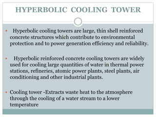
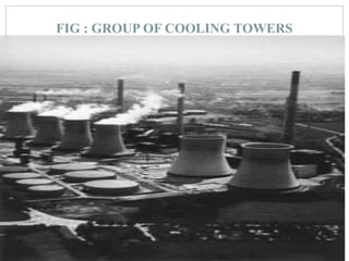
SEMINAR ON
TO STUDY TH E B EH A VIOUR OF H YP ERBOLIC
COOLING TOWER SH ELL WITH PIPEOPENING S
SC A LEDOWN MODEL OF 1:50 SUBJECTED TO
SEISMIC LOA DS
UNDER THE GUIDENCE OF,
SYEED SULAIMAN
(Associate. Professor)
HYPERBOLIC COOLING TOWER
 Hyperbolic cooling towers are large, thin shell reinforced
concrete structures which contribute to environmental
protection and to power generation efficiency and reliability.
 Hyperbolic reinforced concrete cooling towers are widely
used for cooling large quantities of water in thermal power
stations, refineries, atomic power plants, steel plants, air
conditioning and other industrial plants.
 Cooling tower -Extracts waste heat to the atmosphere
through the cooling of a water stream to a lower
temperature
FIG : GROUP OF COOLING TOWERS
TYPES OF COOLING TOWER
 NATURAL DRAFT COOLING TOWER:
 The natural draft or hyperbolic cooling tower makes use of the
difference in temperature between the ambient air and the hotter
air inside the tower.
 As hot air moves upwards through the tower (because hot air
rises), fresh cool air is drawn into the tower through an air inlet at
the bottom.
 Due to the layout of the tower, no fan is required and there is
almost no circulation of hot air that could affect the performance.
NATURAL DRAFT COOLING TOWER
 These cooling towers are mostly only for large heat
duties because large concrete structures are expensive.
 There are two main types of natural draft towers:
 1. Cross flow tower : air is drawn across the falling
water and the fill is located outside the tower
 2. Counter flow tower : air is drawn up through the
falling water and the fill is therefore located inside the
tower, although design depends on specific site
 conditions.
FIG :CROSS FLOW TOWER AND COUNTER FLOW TOWER
MECHANICAL DRAFT COOLING TOWER
 Because of their huge shape, construction difficulties and cost, natural
draft towers have been replaced by mechanical draft towers in many
installations.
 Mechanical draft towers have large fans to force or draw air through
circulated water.
 The water falls downwards over fill surfaces, which helps increase the
contact time between the water and the air.
 There are two different classes of mechanical draft cooling towers:
 1. Forced draft
 2. Induced draft
COMPONENTS OF COOLING TOWER
The most prominent component of a natural draft
cooling tower is the huge, towering shell.
This shell is supported by diagonal, meridional, or
vertical columns bridging the air inlet.
 In order to achieve sufficient resistance against
instability, large cooling tower shells may be
stiffened by additional internal or external rings.
These stiffeners may also serve as a repair or
rehabilitation tool.
FIG : FABRICATION OF SUPPOSTING COLUMANAND
CLIMBING CONSTRUCTION OF SHELL
COOLING TOWER MATERIALS
1. Galvanized steel :
The most cost-effective material of construction for cooling tower
offers a substantial amount of protection as compared to the
lighter zinc thickness used several decades ago.
2. Stainless steel:
Type 304 stainless steel construction is recommended for cooling
tower that are to be used in a highly corrosive environment.
3. Fiber Reinforced plastic towers:
 Currently the first growing segment of the cooling tower market
is structure built with FRP sections.
 This inert inorganic material is strong, light weight, chemically
resistant and able to handle a range of PH values fire-retardant.
 FRP can eliminate the cost of a fire protection system, which can
equal 5-12% of the cost of a cooling tower.
ADVANTAGES OF COOLING TOWER
 1. Light weight, high strength — may reduce support requirements
 2. Corrosion resistant — a good match for the cooling tower
environment
 3. Long-lasting — lower lifetime cost than traditional building
materials
 4. Easy fabrication — weighs less to transport and is quick and easy to
install
 5. Nonconductive and non sparking — won’t conduct electricity and
contains no metal.
 7. Low thermal conductivity — does not easily conduct heat or cold
 8. Industry commitment — Bedford is a member of the Cooling
Technology Institute
DESCRIPTION OF 1:3 SCALE MODEL
The model consisted of six segments; each segment
was3.05 m (10 ft) wide, 1.67 m (5 ft-6 5/8 in.) long and
externally post tensioned together .
Each end segment is provided with an end diaphragm
101.6 mm (4 in.) thick
The model thus has an overall length of 10.36 m (34 ft).
To reduce the volume of the connection between the
shell and the deck ,the top surface of the deck was
fabricated tangent to the bottomsurface of the shell
leaving the middle part of the shell flat.
Segment Fabrication
 For fabrication of the shell-bridge model, a reusable wooden form was
constructed. The segments were cast vertically.
 Handheld vibrators as well as form vibrators were used to consolidate
the concrete in the forms.
 In the first segment, however, large voids in the shell portion of the
cross section were observed after stripping the form. These voids were
caused by air trapped inside the forms
 To avoid trapping air while casting the remaining segments,the forms
were provided with a grid of 3.18 rom (118 in.)diameter holes at
approximately 127 rom (5 in.) on centers,thus permitting the air to
escape.
MODEL TEST AND INSTRUMENT
 The model was instrumented using 61 mm (2.4 in.) longstrain
gauges mounted on the concrete surfaces.
 These gaugeswere positioned to measure the longitudinal and
transversestrains at several longitudinal and transverse sections.
 Strain gauges were also mounted on the posttensioningtendons
and on the two truss elements that connect the curband the edge
beams.
 To determine vertical deflections at several critical
locations,direct current displacement transducers (DCDT)
wereplaced along the curbs, edge beams, and across the width
ofthe model at midspan.
RESPONSE-SPECTRUM SEISMIC ANALYSIS
 This method is presented for a simplified seismic analysis of
nonlinear multidegree-of-freedom structures.
 The method represents an improvement over an earlier attempt to
extend the use of the conventional response-spectrum method to
nonlinear structures.
 It involves the computation of their natural frequencies and
modeshapes on the basis of their initial elastic properties
.
 The procedure is formulatedfor plane rigid frames, but limited to
elastoplasticforce-deformation behavior
FACTORS INFLUENCING RESPONSE SPECTRA
The response spectral values depends upon the following
parameters,
I) Energy release mechanism
II) Epicentral distance
III) Focal depth
IV) Soil condition
V) Richter magnitude
VI) Damping in the system
VII) Time period of the system
FACTORS INFLUENCING RESPONSE SPECTRA
The response spectral values depends upon the following
parameters,
I) Energy release mechanism
II) Epicentral distance
III) Focal depth
IV) Soil condition
V) Richter magnitude
VI) Damping in the system
VII) Time period of the system
SHAKE TABLE
 The shake table is an indispensable testing facility for development of
earthquakeresistanttechniques.
 A shaking table is a platform excited with servo-hydraulic actuators
to simulate different types of periodic and random motions, such as artificial
earthquakesand other dynamic testing signals of interest in the laboratory.
 This is the onlyexperimental technique for direct simulation of inertia forces,
which can be used to simulate different types of motion such as recorded
earthquake ground motions, harmonic motions,sine sweeps (increasing,
decreasing), Sine, Random etc..
 Shaketable test results enhance further the understanding of the behavior of
structures andcalibration of various numerical tools used for analysis.
MAJOR PARTS OF SHAKE TABLE

 SHAKE TABLE WITH LINEAR RAIL GUIDE
 ACTUATOR ASSEMBLY UNIT
a) Actuator with Servo valve
b) Load Cell
c) Displacement Transducer
 HYDRAULIC POWER PACK
 ELECTRICAL CONTROL CABINET : Consisting of electrical
components like :-
(1) Contactors
(2) Time delay relays
(3) Power inlet points
(4) Indicating lamps(RYB)
(5) Temperature Controller
CONCLUSION
 A shake table can be used to test the resistance of structures to
shaking.
It is evident from the sysmic analysis the principle stress observed to
be least.
It can also be used to demonstrate the sensitivity of structures of
different heights to the frequency of the ground motion.
The use of shake tables to demonstrate earthquake hazards largely has
been pioneered by the earthquake engineering community, which
possesses considerable experience in this area.
If the dimension is less deflection is less and if the dimension is more
REFRENCES
1) G. Murali, C. M. Vivek Vardhan and B. V. Prasanth Kumar ReddyRESPONSE OF
COOLING TOWERS TO WIND LOADS, ARPN Journal of Engineering
andApplied Sciences
2) D. Makovička, Response Analysis of RC cooling tower under seismic and wind
storm effect, Acta Polytechnica Vol. 46 No. 6/2006.
3) A. M. El Ansary, A. A. El Damatty, and A. O. Nassef, Optimum Shape and Design
of Cooling Towers, World Academy of Science, Engineering and Technology 60
2011.
4) R.L.Norton, & v.i Weingarten, the effect of asymmetric imperfections on the
earthquake response of hyperbolic cooling towers.
5) Shailesh S. Angalekar, Dr. A. B. Kulkarni, Analysis of natural draught
hyperboliccooling tower by finite element method using equivalent plate method.
6) IS: 11504:1985, Criteria for structural design of reinforced concrete natural draught
cooling tower, New Delhi, India: Bureau of Indian standards.
Ppt

Ppt

  • 1.
    SEMINAR ON TO STUDYTH E B EH A VIOUR OF H YP ERBOLIC COOLING TOWER SH ELL WITH PIPEOPENING S SC A LEDOWN MODEL OF 1:50 SUBJECTED TO SEISMIC LOA DS UNDER THE GUIDENCE OF, SYEED SULAIMAN (Associate. Professor)
  • 2.
    HYPERBOLIC COOLING TOWER Hyperbolic cooling towers are large, thin shell reinforced concrete structures which contribute to environmental protection and to power generation efficiency and reliability.  Hyperbolic reinforced concrete cooling towers are widely used for cooling large quantities of water in thermal power stations, refineries, atomic power plants, steel plants, air conditioning and other industrial plants.  Cooling tower -Extracts waste heat to the atmosphere through the cooling of a water stream to a lower temperature
  • 3.
    FIG : GROUPOF COOLING TOWERS
  • 4.
    TYPES OF COOLINGTOWER  NATURAL DRAFT COOLING TOWER:  The natural draft or hyperbolic cooling tower makes use of the difference in temperature between the ambient air and the hotter air inside the tower.  As hot air moves upwards through the tower (because hot air rises), fresh cool air is drawn into the tower through an air inlet at the bottom.  Due to the layout of the tower, no fan is required and there is almost no circulation of hot air that could affect the performance.
  • 5.
    NATURAL DRAFT COOLINGTOWER  These cooling towers are mostly only for large heat duties because large concrete structures are expensive.  There are two main types of natural draft towers:  1. Cross flow tower : air is drawn across the falling water and the fill is located outside the tower  2. Counter flow tower : air is drawn up through the falling water and the fill is therefore located inside the tower, although design depends on specific site  conditions.
  • 6.
    FIG :CROSS FLOWTOWER AND COUNTER FLOW TOWER
  • 7.
    MECHANICAL DRAFT COOLINGTOWER  Because of their huge shape, construction difficulties and cost, natural draft towers have been replaced by mechanical draft towers in many installations.  Mechanical draft towers have large fans to force or draw air through circulated water.  The water falls downwards over fill surfaces, which helps increase the contact time between the water and the air.  There are two different classes of mechanical draft cooling towers:  1. Forced draft  2. Induced draft
  • 8.
    COMPONENTS OF COOLINGTOWER The most prominent component of a natural draft cooling tower is the huge, towering shell. This shell is supported by diagonal, meridional, or vertical columns bridging the air inlet.  In order to achieve sufficient resistance against instability, large cooling tower shells may be stiffened by additional internal or external rings. These stiffeners may also serve as a repair or rehabilitation tool.
  • 9.
    FIG : FABRICATIONOF SUPPOSTING COLUMANAND CLIMBING CONSTRUCTION OF SHELL
  • 10.
    COOLING TOWER MATERIALS 1.Galvanized steel : The most cost-effective material of construction for cooling tower offers a substantial amount of protection as compared to the lighter zinc thickness used several decades ago. 2. Stainless steel: Type 304 stainless steel construction is recommended for cooling tower that are to be used in a highly corrosive environment. 3. Fiber Reinforced plastic towers:  Currently the first growing segment of the cooling tower market is structure built with FRP sections.  This inert inorganic material is strong, light weight, chemically resistant and able to handle a range of PH values fire-retardant.  FRP can eliminate the cost of a fire protection system, which can equal 5-12% of the cost of a cooling tower.
  • 11.
    ADVANTAGES OF COOLINGTOWER  1. Light weight, high strength — may reduce support requirements  2. Corrosion resistant — a good match for the cooling tower environment  3. Long-lasting — lower lifetime cost than traditional building materials  4. Easy fabrication — weighs less to transport and is quick and easy to install  5. Nonconductive and non sparking — won’t conduct electricity and contains no metal.  7. Low thermal conductivity — does not easily conduct heat or cold  8. Industry commitment — Bedford is a member of the Cooling Technology Institute
  • 12.
    DESCRIPTION OF 1:3SCALE MODEL The model consisted of six segments; each segment was3.05 m (10 ft) wide, 1.67 m (5 ft-6 5/8 in.) long and externally post tensioned together . Each end segment is provided with an end diaphragm 101.6 mm (4 in.) thick The model thus has an overall length of 10.36 m (34 ft). To reduce the volume of the connection between the shell and the deck ,the top surface of the deck was fabricated tangent to the bottomsurface of the shell leaving the middle part of the shell flat.
  • 13.
    Segment Fabrication  Forfabrication of the shell-bridge model, a reusable wooden form was constructed. The segments were cast vertically.  Handheld vibrators as well as form vibrators were used to consolidate the concrete in the forms.  In the first segment, however, large voids in the shell portion of the cross section were observed after stripping the form. These voids were caused by air trapped inside the forms  To avoid trapping air while casting the remaining segments,the forms were provided with a grid of 3.18 rom (118 in.)diameter holes at approximately 127 rom (5 in.) on centers,thus permitting the air to escape.
  • 14.
    MODEL TEST ANDINSTRUMENT  The model was instrumented using 61 mm (2.4 in.) longstrain gauges mounted on the concrete surfaces.  These gaugeswere positioned to measure the longitudinal and transversestrains at several longitudinal and transverse sections.  Strain gauges were also mounted on the posttensioningtendons and on the two truss elements that connect the curband the edge beams.  To determine vertical deflections at several critical locations,direct current displacement transducers (DCDT) wereplaced along the curbs, edge beams, and across the width ofthe model at midspan.
  • 15.
    RESPONSE-SPECTRUM SEISMIC ANALYSIS This method is presented for a simplified seismic analysis of nonlinear multidegree-of-freedom structures.  The method represents an improvement over an earlier attempt to extend the use of the conventional response-spectrum method to nonlinear structures.  It involves the computation of their natural frequencies and modeshapes on the basis of their initial elastic properties .  The procedure is formulatedfor plane rigid frames, but limited to elastoplasticforce-deformation behavior
  • 16.
    FACTORS INFLUENCING RESPONSESPECTRA The response spectral values depends upon the following parameters, I) Energy release mechanism II) Epicentral distance III) Focal depth IV) Soil condition V) Richter magnitude VI) Damping in the system VII) Time period of the system
  • 17.
    FACTORS INFLUENCING RESPONSESPECTRA The response spectral values depends upon the following parameters, I) Energy release mechanism II) Epicentral distance III) Focal depth IV) Soil condition V) Richter magnitude VI) Damping in the system VII) Time period of the system
  • 18.
    SHAKE TABLE  Theshake table is an indispensable testing facility for development of earthquakeresistanttechniques.  A shaking table is a platform excited with servo-hydraulic actuators to simulate different types of periodic and random motions, such as artificial earthquakesand other dynamic testing signals of interest in the laboratory.  This is the onlyexperimental technique for direct simulation of inertia forces, which can be used to simulate different types of motion such as recorded earthquake ground motions, harmonic motions,sine sweeps (increasing, decreasing), Sine, Random etc..  Shaketable test results enhance further the understanding of the behavior of structures andcalibration of various numerical tools used for analysis.
  • 19.
    MAJOR PARTS OFSHAKE TABLE   SHAKE TABLE WITH LINEAR RAIL GUIDE  ACTUATOR ASSEMBLY UNIT a) Actuator with Servo valve b) Load Cell c) Displacement Transducer  HYDRAULIC POWER PACK  ELECTRICAL CONTROL CABINET : Consisting of electrical components like :- (1) Contactors (2) Time delay relays (3) Power inlet points (4) Indicating lamps(RYB) (5) Temperature Controller
  • 20.
    CONCLUSION  A shaketable can be used to test the resistance of structures to shaking. It is evident from the sysmic analysis the principle stress observed to be least. It can also be used to demonstrate the sensitivity of structures of different heights to the frequency of the ground motion. The use of shake tables to demonstrate earthquake hazards largely has been pioneered by the earthquake engineering community, which possesses considerable experience in this area. If the dimension is less deflection is less and if the dimension is more
  • 21.
    REFRENCES 1) G. Murali,C. M. Vivek Vardhan and B. V. Prasanth Kumar ReddyRESPONSE OF COOLING TOWERS TO WIND LOADS, ARPN Journal of Engineering andApplied Sciences 2) D. Makovička, Response Analysis of RC cooling tower under seismic and wind storm effect, Acta Polytechnica Vol. 46 No. 6/2006. 3) A. M. El Ansary, A. A. El Damatty, and A. O. Nassef, Optimum Shape and Design of Cooling Towers, World Academy of Science, Engineering and Technology 60 2011. 4) R.L.Norton, & v.i Weingarten, the effect of asymmetric imperfections on the earthquake response of hyperbolic cooling towers. 5) Shailesh S. Angalekar, Dr. A. B. Kulkarni, Analysis of natural draught hyperboliccooling tower by finite element method using equivalent plate method. 6) IS: 11504:1985, Criteria for structural design of reinforced concrete natural draught cooling tower, New Delhi, India: Bureau of Indian standards.