Downloaded 25 times
![MECHANICAL DRIVES &
TRANSMISSION USED FOR TEXTILE
PROCESS MACHINES
BY
UMESH PATEL.[AGM
ENGG]HIMATSINGKA,[9980017879]
<umeshpatel123@yahoo.com>](https://image.slidesharecdn.com/mech-170606144251/85/Mech-drives-Transmission-for-textile-process-machines-1-320.jpg)
![MECHANICAL DRIVES &
TRANSMISSION USED FOR TEXTILE
PROCESS MACHINES
BY
UMESH PATEL.[AGM
ENGG]HIMATSINGKA,[9980017879]
<umeshpatel123@yahoo.com>](https://image.slidesharecdn.com/mech-170606144251/75/Mech-drives-Transmission-for-textile-process-machines-1-2048.jpg)
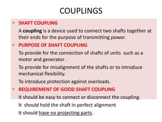
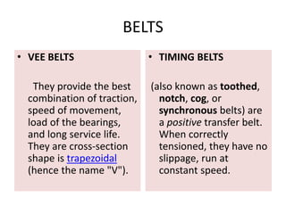

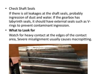
![How to Inspect a Gearbox
• [a] Good Housekeeping is Essential
Many gearboxes operate in dirty environments
during inspection which may mislead to oil level,
ventilation plug, etc.
• [b] Walkaround Visual Inspection
Before cleaning the gear housing, inspect it for
signs of overheating, corrosion, contamination,
oil leaks and damage.
Measure the tightening torque of structural
fasteners that carry significant loads such as
torque arm bolts.](https://image.slidesharecdn.com/mech-170606144251/85/Mech-drives-Transmission-for-textile-process-machines-48-320.jpg)

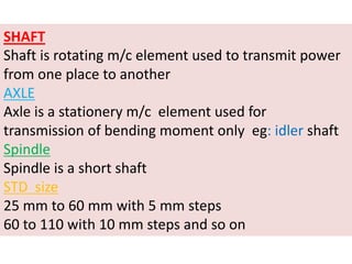
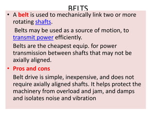
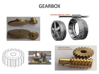
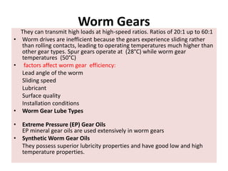
This document discusses mechanical drives and transmissions used for textile process machines. It covers various components used such as shafts, axles, spindles, keys, couplings, belts, chains, gears and gearboxes. It provides details on the types of each component, governing equations, material selection, inspection methods, common failures and maintenance practices. The document is an informative reference for the mechanical components used to transmit power in textile machinery.


