SlideShare a Scribd company logo
1 of 33
Download to read offline
Principle of Operation
DC motor operates on the principle that when a current carrying is placed in a magnetic field, it
experiences a mechanical force given by F = BIL newton. Where
the current and ‘L’ is the length of the conductor. The direction of force can be found by
left hand rule. Constructionally, there is no difference between a DC generator and DC motor.
conductors. The collective force produces a driving torque which sets the armature into rotation.
The function of a commutator in DC motor is to provide a contin
In DC generator the work done in overcoming the magnetic drag is converted into electrical energy.
Conversion of energy from electrical form to mechanical form by a DC motor takes place by the
work done in overcoming the opposition which is called the
BACK EMF: is the dynamically induced emf in the armature conductors of a dc motor when the
armature is rotated. The direction of the induced emf as found by Flemings right hand rule is in
opposition to the applied voltage. Its value is same as that
i.e.,  


volts. This emf is called as back
opposition is converted into mechanical energy.
SIGNIFICANCE OF BACK EMF
generating the back emf′

is like a
From Figure 2.2,  


where 


Volts.  ∝ .
Figure 2.1
UNIT – 2
DC MOTORS
DC motor operates on the principle that when a current carrying is placed in a magnetic field, it
experiences a mechanical force given by F = BIL newton. Where ‘B’ = flux density in wb/
is the length of the conductor. The direction of force can be found by
left hand rule. Constructionally, there is no difference between a DC generator and DC motor.
Figure 2.1 shows a multipolar DC motor. Armature
conductors are carrying current downwards under
North Pole and upwards under South Pole. When the
field coils are excited, with current carrying armature
conductors, a force is experienced by each armature
conductor whose direction can be found by Fleming’s
left hand rule. This is shown by arrows
. The collective force produces a driving torque which sets the armature into rotation.
The function of a commutator in DC motor is to provide a continuous and unidirectional torque.
In DC generator the work done in overcoming the magnetic drag is converted into electrical energy.
Conversion of energy from electrical form to mechanical form by a DC motor takes place by the
work done in overcoming the opposition which is called the ‘back emf’.
is the dynamically induced emf in the armature conductors of a dc motor when the
armature is rotated. The direction of the induced emf as found by Flemings right hand rule is in
opposition to the applied voltage. Its value is same as that of the induced emf in a DC generator
volts. This emf is called as back emf′

. The work done in overcoming this
opposition is converted into mechanical energy.
SIGNIFICANCE OF BACK EMF: Figure 2.2 shows a DC shunt motor. The rot
battery of emf ′

connected across a supplyvoltage of ‘
   ! !#$%!.
DC motor operates on the principle that when a current carrying is placed in a magnetic field, it
= flux density in wb/'
, ‘I’ is
is the length of the conductor. The direction of force can be found by Fleming’s
left hand rule. Constructionally, there is no difference between a DC generator and DC motor.
shows a multipolar DC motor. Armature
conductors are carrying current downwards under
North Pole and upwards under South Pole. When the
field coils are excited, with current carrying armature
conductors, a force is experienced by each armature
hose direction can be found by Fleming’s
left hand rule. This is shown by arrows on top of the
. The collective force produces a driving torque which sets the armature into rotation.
uous and unidirectional torque.
In DC generator the work done in overcoming the magnetic drag is converted into electrical energy.
Conversion of energy from electrical form to mechanical form by a DC motor takes place by the
is the dynamically induced emf in the armature conductors of a dc motor when the
armature is rotated. The direction of the induced emf as found by Flemings right hand rule is in
of the induced emf in a DC generator
. The work done in overcoming this
The rotating armature
connected across a supplyvoltage of ‘V’ volts.
www.getmyuni.com
If  is large, armature current will be less and vice versa. Hence  acts like a governor i.e., it
makes the motor self- regulating so that it draws as much current as required by the motor.
VOLTAGE EQUATION OF A MOTOR:
The voltage ‘V’ applied across the motor armature has to
i) Overcome the back emf  and
ii) Supply the armature ohmic drop 
Hence (   ) …..1 This is known as voltage
equation of DC motor.
Multiplying both sides of voltage equation by 
(   ) 
'
…….2
(  !*!%#%* #$+  , -!  !.
  ./  !*!%#%* !0 #1*!$ ,2 !%-$#%*
+,3! 4!1!*,+!4 #$ -!  !.

'
   ! %,++! *,
CONDITION FOR MAXIMUM POWER
Mechanical power developed by the motor is ./  ( 5 
'
…….3
Condition for maximum power is
6 7
68
 0
4.
/
4
 ( 5 2  0
(
2
 
(   )

'
 

'
………4
Thus the mechanical power developed by the motor is maximum when the back emf is equal to half
the applied voltage.
Figure 2.2
www.getmyuni.com
TORQUE:
Torque is the twisting moment about an axis. It is measured by the product of the force and the
radius at which the force acts. Consider a pulley of radius ‘r’ metre acted upon a circumferential
force of ‘F’ newton which causes it to rotate at ‘N’ rotations per second (r.p.s) as show in Figure. 2.3
T = F X r N-metre
Work done by this force in one revolution = Force X Distance = F X 2π r joule.
Power Developed = F X 2 π r X N joule/sec.
= (F X r) 2π N joule/sec
2πN = angular revolution ω in rad/sec. And F X r = Torque ‘T’
Therefore Power Developed = T X ω joule/sec or watts…….. 5
ARMATURE TORQUE OF A MOTOR:
Let Ta = armature torque in N –m developed by the armature of a motor running at N.rps.
Therefore P = Ta X 2π N Watts …….. 6
Electrical equivalent of mechanical power developed Pm = 
  ; 2
Ta =
=
'
8

N – m ……....7
= 0.0162
8

kg-m ……..8
Also, on substituting for Eb i.e., ФZN  
ФZN    ; 2
Therefore Ta =
=
'
Ф?  N-mtrs
Figure 2.3
www.getmyuni.com
26
Ta = 0.159 Ф Z   N-mtrs …..9
=0.162 Ф Z   kg-mtrs ……..10
(1 Kg = 9.81 N)
From the above equation for torque, it is seen that
(i) T Ф 
(ii) T∝ 
'
- For series motor (because Ф∝ ) before saturation. After saturation ; ∝ .
(iii) ; ∝  - For shunt motor. (because Ф is constant in a shunt motor)
SHAFT TORQUE (TSH):
Some of the torque developed in the armature will be lost in supplying the iron and friction losses in
the motor. The torque which is available for doing useful work is known as shaft torque ‘Tsh’. The
horse power obtained by using the shaft torque is called as Brake Horse Power (BHP).
BHP =
@ABC '
DEF.F
………..11
Tsh =
GH C DEF.F
'
=
IJKLJK M NKKO
'
N-m
Lost torque = ;−;OP
= 0.159 X
8I 6 QMRKMI SIOOTO M UKKO

N-mtrs ………12
= 0.162 X
8I 6 QMRKMI SIOOTO M UKKO

kg-mtrs ………13
SPEED OF A DC MOTOR:
 = ( −  Or ФZN = ( − 
N =

Ф
 r.p.s
N= K

Ф
N ∝

Ф
; ∝ ∅ 
∅ = W,$$, if ∅ = constant, then ; ∝  ………….14
www.getmyuni.com
27
(i) For series motor, = ∝
X
ФX
N2∝
Y
ФY
where = = ( − =
' = ( − '
Y
X
=
Y
X
8X
8Y
Or
Y
X
=
Y
X
ФX
ФY
………..15
(ii) For shunt motor.
'
=
=
'
=
Ф=
Ф'
Ф = constant for shunt motor
Ф1 = Ф2
Y
X

Y
X
………….16
Speed regulation: is defined as the change in speed from No-load to full load when the rated load on
the motor is reduced to zero, expressed as a percentage of rated speed.
% speed regulation =
ISI6OLTT6QJZZ ZI6OLTT6
QJZZSI6OLTT6
=
6

100
CHARACTERISTICS OF DC MOTORS:
There are three important characteristics.
1. Armature torque vs Armature current ;vs  (Electrical characteristics)
2. Speed vs armature current characteristic
3. Speed vs torque N vs; (Mechanical characteristics)
CHARACTERISTICS OF SHUNT MOTORS
i)
@
8
ii)

8
###)

@

N
;


;
Figure 2.4 Figure 2.5 Figure 2.6
www.getmyuni.com
28
N α

∅
or N = h(
8i
∅
) ; N =
jk
∅
-
jk8
∅
------- (a)
 
@
jl∅
-------(b)
Substituting (b) in(a)
N =
jk
∅
-
jk
jl∅Y ; --------- (17)
m. nopq roCHARACTERISTICS
For a shunt motor flux can be assumed practically constant (at heavy loads, decreases, due to
increased armature reaction)
; ∝ ∅ 
∅ = %,$$, ; ∝ 
Therefore electrical characteristic of a shunt motor is a straight line through origin shown by dotted
line in Figure 2.4. Armature reaction weakens the flux hence ;1  characteristic bends as shown
by dark line in figure 2.4, Shunt motors should never be started on heavy loads, since it draws heavy
current under such condition.
t. u pq roCHARACTERISTICS
 ∝  ; is practically almost constant.
Hence the speed is constant. However,  decreases slightly more than with increase in load and
thus there is slight decrease in speed. This decrease in speed varies from 5 to 15% of full load speed
and it depends on armature reaction and saturation. This characteristics is shown in Figure 2.5
v. u pq noCHARACTERISTICS
This characteristic can be deduced from 1 and 2, shown in figure 2.6
www.getmyuni.com
Performance curves of DC shunt motor
The four essential characteristics of shunt motor i.e., torque, speed, current and efficiency plotted as
a function of horse power are known as performance curves of the motor, shown in figure 2.7
Shunt motor has a definite No-load speed hence can be used where a load is suddenly thrown off
with field circuit remaining close. The drop in speed from No-load to full load is small and hence
referred to as constant speed motor. The efficiency curve is usually of the same shape for all motors
and generators. It is advantageous to have an efficiency curve which is fairly flat and the maximum
efficiency near to full load. Certain value of minimum current is required even when the output is
zero as the input under No-load condition has to meet the losses within the machine.
The shunt motor is also capable of starting under heavy load condition but the current drawn by the
motor will be very high (; ∝ )compared to DC series motor. As the series motor draws only one
and half times the full load current; ∝ 
'
,  ∝ w;.
CHARACTERISTICS OF SERIES MOTORS
m. nopq ro CHARACTERISTICS
; ∝ ∅ 
∅ ∝ 
; ∝ 
'
– upto saturation ………. 18
; ∝  – after saturation ………. 19

;
;
;OP
Figure 2.7
Figure 2.8
www.getmyuni.com
30
At light loads, and hence is small. But as increases ; increases as the square of the current up
to saturation. After saturation becomes constant, the characteristic becomes a straight line as
shown in Figure 2.8. Therefore a series motor develops a torque proportional to the square of the
armature current. This characteristic is suited where huge starting torque is required for accelerating
heavy masses.
Ex. Hoists, electric trains, etc.
t. u pq roCHARACTERISTICS
 ∝

∅
 # ++,x#!*y %,$$
 ∝
=
∅
………….20
If  increases, ∅ increases and hence speed decreases.
This characteristic is shown in figure 2.9(a). Change in
 for various load currents is small. Hence may be neglected. Therefore the speed is inversely
proportional to flux, because  ∝

∅
. When the load is heavy,  is large and speed is low. When the
load is low, current and hence flux will be small. Therefore speed becomes dangerously high. Hence
a series motor should never be started without load on it.
v. u pq noCHARACTERISTICS
; ∝ 
# %,$$
Hence, ; ∝ . Therefore, N vs ;characteristic
can be deduced from 1 and 2 as shown in Figure 2.9 (b)


Figure 2.9 (a)

;
Figure 2.9 (b)
www.getmyuni.com
PERFORMANCE CURVES OF DC SERIES MOTOR
The performance curves of DC series motor are
Figure 2.10. The machine is so designed that it is having
maximum efficiency near rated load.
For a given input current, the starting torque developed by
a DC series motor is greater than that developed by a
shunt motor. Hence series motors are used where huge
starting torques are necessary. Ex. Cranes, hoists, electric
traction etc. The DC series motor responds by decreasing
its speed for the increased in load. The current drawn by
the DC series motor for the given increase in load
than DC shunt motor. The drop in speed with increased
load is much more prominent in series motor than that in a
shunt motor. Hence series motor is not suitable for applications requiring a constant speed.
COMPOUND MOTOR CHARACTERISTICS
Cumulative compound motors:
characteristics are required and in addition the load is likely to be
removed totally such as in some types of coal cutting machines or
for driving heavy machine tools which have to take sudden deep
cuts quite often. Speed will not become excessively high due to
shunt winding and the motor will be able to take heavy loads
because of series winding.
Differential compound motors: Series field opposes the shunt
field; therefore the flux is decreased as the load is ap
motor. This results in the motor speed remaining almost constant
or even increasing with increase in load.
Summarizing,
1.

8
Lies between shunt ( = constant) and series (
characteristics as shown in figure 2.11
2. Used in rolling mills where light and heavy loads are thrown on
the motor.
PERFORMANCE CURVES OF DC SERIES MOTOR
The performance curves of DC series motor are shown in
Figure 2.10. The machine is so designed that it is having
maximum efficiency near rated load.
For a given input current, the starting torque developed by
a DC series motor is greater than that developed by a
es motors are used where huge
starting torques are necessary. Ex. Cranes, hoists, electric
traction etc. The DC series motor responds by decreasing
its speed for the increased in load. The current drawn by
the DC series motor for the given increase in load is lesser
than DC shunt motor. The drop in speed with increased
load is much more prominent in series motor than that in a
shunt motor. Hence series motor is not suitable for applications requiring a constant speed.
COMPOUND MOTOR CHARACTERISTICS
are used where series
characteristics are required and in addition the load is likely to be
removed totally such as in some types of coal cutting machines or
for driving heavy machine tools which have to take sudden deep
ten. Speed will not become excessively high due to
shunt winding and the motor will be able to take heavy loads
Series field opposes the shunt
therefore the flux is decreased as the load is applied to the
motor. This results in the motor speed remaining almost constant
or even increasing with increase in load.
= constant) and series (∅ ∝ )
in figure 2.11.
rolling mills where light and heavy loads are thrown on
Figure 2.10
Figure 2.11
shunt motor. Hence series motor is not suitable for applications requiring a constant speed.
Figure 2.10
Figure 2.11
www.getmyuni.com
3. Cumulative compound motor has a finite No-load speed and has a load – relieving
characteristics of a series motor under heavy load conditions.
4. Differential compound motors are seldom used in practice.(because of rising speed
characteristics)
SPEED CONTROL OF DC MOTORS
DC motors are in general much more adaptable speed drives than AC motors. Speed of a DC motor
can be controlled in a wide range.
  h

∅
 h
8g
∅
Since armature resistance drop is small, N = h

∅
………….21
From the above equation, two methods of speed control are possible.
1. Variation of field current which varies the flux/pole (Ф) and is known as field control.
2. Variation of terminal voltage ‘V’ known as armature voltage control.
FIELD CONTROL:
For a fixed terminal voltage,
Y
X

ФX
ФY

8{X
8{Y
(for linear magnetization) …………..22
Limitations of speed control by field control:
1. ‘N’ below rated speed is not possible. Because Ф can be decreased and cannot increase.
2. N∝
=
Ф
; ∝ } for a given armature current, this method suits for constant kW drives only
where ‘T’ decreases if speed decreases.
3. Not suited for speed reversal.
DC SHUNT MOTOR:
N =
jk
Ф
5 
jk
jlФY T ………23
Figure 2.13
Figure 2.12
www.getmyuni.com
Speed control is achieved by means of a rheostat in the field circuit as shown in the Figure 2.12. The
speed torque characteristics have a small linear drop due to the second term (ra effect) in the above
equation. The field is weakened due to the armature reaction. The working range of the speed torque
characteristics reduces with increasing speed in order for the armature current not to exceed the full
load value with a weakening field. The speed – torque curves are shown in Figure 2.13
DC SERIES MOTOR:
Speed control is achieved by adjusting the field ampere turns. There are three ways for varying the
field ampere turns.
1. DIVERTER FIELD CONTROL:
Diverter resistance Rdis connected across the
field winding as shown in Figure 2.14. By
varying Rd the field current and hence the field
ampere turns can be reduced. Therefore, the field
current is given by
If = Ia
i~
i~ iA€
KdIa……24
Where Kd =
i~
i~ iA€
Kd =
=
=
A€
~
We know that, for series motor N =
8( A€)
Ф
And T 0∝ Ф or T = h@Ф
T = h@h‚
'
, Ia = ƒ
@
jlj{
If there is no Rd, then Ф = h‚
N = h „

Ф
5
8( )
Ф
†
N=KN‡

j{8
√@( A€)
wjlwj{ .j{
√l
w‰lƒ‰{
Š
Figure 2.14
www.getmyuni.com
N =
jk
j{
„

8
5 ( ) OT)† …….25
If Rd is introduced then,
Ф = KdKf Ia.
Therefore N = h „

Ф
5
8( A€)
Ф
†
KN‹

j~j{8
5
8( A€||i~)
j~j{8

Substituting   ƒ
@
j~j{
N 
jk
j{
‹
wj{jl
√@wj~
5
(  A€||i~)
j~
 ………..26
From the above equation speed torque characteristics for decreasing values of Kd are plotted which is
shown in above Figure 2.15.
2. Tapped field control:
The field ampere turns are adjusted in steps by varying the number of turns included in the circuit as
shown in figure 2.16, the following relations are obtained from the circuit.
AT (effective) =
A€
|
A€
Ia = hOT
Therefore Ф = h‚hOT ………… 27
Decreasing Kd
N
T
Figure 2.15
Figure 2.16
www.getmyuni.com
Nse
|
= turns with rse
|
= Kserse
T = h‚hOThK
'
  ƒ
@
jlj{jA€
………28
From equation 25, N =
jk
j{
„

8
5 () OT)†
Substituting   ƒ
@
jlj{jA€
,
N =
jk
j{
‹
wjlj{jA€
√@
5 ( ) hOTOT)
The speed torque characteristics are shown in figure 2.17 and are of similar to those of diverter field
control.
3. Series parallel control:
In this method, the field windings are divided into two equal halves and then connected in series or
parallel to control the field ampere turns as shown in figure 2.18 and 2.19 respectively.
2
A€
'
8
'
= AT parallel …………. 30
AT parallel =
=
'
(Ž;!#!) ………. 31
Ф =
=
'
h‚
Kse = 1 or
=
'
i.e., only two speeds are possible; parallel field connection gives the higher speed, series
field connection gives the lower speed.
Decreasing Kse
N
T
Figure 2.17
Figure 2.18 Figure 2.19
www.getmyuni.com
COMPARISION OF TORQUE DEVELOPED BY MOTORS IN SERIES AND PARALLEL
CONNECTION:
MOTORS IN SERIES:
 ∝

Y
8
∝

'8
………… 32
This speed is 1/4th
of the speed of the motor, when in parallel.
T ∝ ФI ∝ '
………... 33
Torque is four times that produced by motors when in parallel.
MOTORS IN PARALLEL:


Ф



(!#! ,,)
Since  ≅ (;  ∝

’
Y
∝
'
8
; Torque Ф I ∝ '
;
Therefore T ∝ 
8
'
'
; T ∝
8Y
“
……… 34
From equations 33 and 34 torque developed in series connection is four times that of motors in
parallel connection.
ARMATURE VOLTAGE CONTROL:
In this method, applied voltage across the armature of the DC motor is varied. This method is
superior to field control in the following aspects:
1. This method provides a constant torque drive.(if the Ф and Ia are maximum, maximum torque
can be obtained as T Ф )
2. Since main field ampere turns are maintained at large value, flux density distortion caused by
armature reaction is limited.
3. Unlike field control scheme, speed reversal can be easily implemented.
This method requires a variable voltage supply which makes this method costlier.
DC SHUNT MOTOR:
Following are the armature control schemes for DC shunt motor.
1. Rheostatic control:
Figure 2.20
Figure 2.21
www.getmyuni.com
Here the applied armature voltage is varied by placing an adjustable resistance ‘R’ in series with the
armature as shown in the Figure 2.22. N vs T for varying ‘R’ is shown in figure 2.23.
Some of the limitations of the rheostatic method are:
1. Speeds only below rated speed
2. Range of speeds is limited because efficiency reduces drastically for large speed reductions
η/


(

(( 5 T)
(

1 5 T
(
3. Speed regulation is poor. Because for a given resistance re, N varies directly with load.
Therefore this method is suitable for very small (fractional kW) or for short-time, intermittent
slowdowns for medium sized motors.
I ∝ (5I
= ∝ (- ( ) ”)


( 5 ( ) ”)
( 5  


( 5 ( ) ”)
(
The load current for which N= 0 is
0 =  1 5
8Xi•

0  1 5
8Xi•

;
8Xi•

 1 ; = 

i•
……… 35
This is the maximum current and  is the No-load speed shown in figure 2.24
N
Ia
N0
Figure 2.22
Figure 2.23
Figure 2.24
www.getmyuni.com
1. Shunted armature control:
In the armature rheostatic control method, the change in armature current due to change in load will
affect the speed. Hence in this method the armature is shunted by an adjustable resistance as shown
in Figure 2.25.
Advantages of this method are
a. Speed regulation will be better.
b. The changes in the armature current due to
load will not be as effective as the armature is connected
across a resistance.
SERIES PARALLEL CONTROL OF SHUNT MOTOR:
In this method the two identical motors are coupled together mechanically to a common load. Two
speeds at constant torque are possible in this method – one by connecting motor armature in series
and the other by connecting them in parallel as shown in figures 2.26 and 2.27 respectively. When
connected in series the voltage across each motor is half the supply voltage and when in parallel,
each armature carries full supply voltage.
This method is superior to rheostatic control so far as efficiency is concerned but the speeds that can
be obtained can only be two steps. This method is commonly employed for speed control of series
traction motors.
Figure 2.25
Figure 2.26 Figure 2.27
www.getmyuni.com
WARD-LEONARD METHOD OF SPEED CONTROL:
It is a combined armature and field control and is therefore operationally the most efficient method
of speed control with a wide range. ‘M’ is the main motor whose speed control is required. The field
of this motor is permanently connected across the DC supply lines. Its armature is supplied by a
variable voltage derived by a polyphase Induction Motor-DC generator set. The field of the DC
generator is excited from an exciter coupled to the extension of the induction motor shaft. The entire
arrangement is shown in the figure 2.28. The reversible switch provided for the generator makes it
possible to easily reverse the generator excitation thereby reversing the voltage polarity for reversing
the direction of rotation of motor. Though expensive, this arrangement can be easily adapted to
feedback schemes for automatic control of speed. This method provides both constant torque and
constant HP (or kW) drive.
The motor armature and its field winding are fed at
maximum values at the base speed Nbase. Reducing
armature voltage provides a constant torque speed control
where the speed can be reduced below the base value,
while the motor has full torque capability. For obtaining
speeds above Nbase the field is gradually weakened. The
motor torque therefore reduces as its speed increases
which corresponds to constant kW (or HP) drive. This is
shown in the Figure 2.29.
Figure 2.28
Figure 2.29
www.getmyuni.com
40
Some of the features of the Ward Leonard system are given below:
1. Absence of external resistance improves efficiency at all speeds and also when the generator
emf becomes less than the back emf of the motor, the electrical power flows back from motor
to generator, is converted to mechanical form and is returned to the mains via the driving AC
motor.
2. Motor starts up smoothly therefore No starting device is required.
3. Speed reversal is smoothly carried out.
4. Fine speed control from zero to rated value in both the directions.
This method of speed control is used in
a. High speed elevators
b. Colliery winders
Advantages
1. Absence of external resistance improves efficiency at all speeds
2. Motor starts up smoothly. No starting device is required
3. Speed reversal is smoothly carried out
STARTERS FOR DC MOTORS
Necessity of starter:
The current drawn by the armature is given by  
 
i
. At starting,   0 because N = 0.
Armature resistance will be very low. Therefore, the current drawn by the motor will be very high. In
order to limit this high current, a starting resistance is connected in series with the armature. The
starting resistance will be excluded from the circuit after the motor attains its rated speed. From there
on back emf limits the current drawn by the motor. The arrangement is shown in the figure 2.30
which is a three point starter for shunt motor.
Three Point Starter:
It consists of resistances arranged in steps, ”=to ”Fconnected in series with the armature of the shunt
motor. Field winding is connected across the supply through a protective device called ‘NO – Volt
Coil’. Another protection given to the motor in this starter is ‘over load release coil’. The
arrangement is shown in Figure 2.30
30
www.getmyuni.com
To start the motor the starter handle is moved from OFF position to Run position gradually against
the tension of a hinged spring. An iron piece is attached to the starter handle which is kept hold by
the No-volt coil at Run position. The
function of No volt coil is to get
deenergised and release the handle when
there is failure or disconnection or a
break in the field circuit so that on
restoration of supply, armature of the
motor will not be connected across the
lines without starter resistance. If the
motor is over loaded beyond a certain
predetermined value, then the
electromagnet of overload release will
exert a force enough to attract the lever
which short circuits the electromagnet of
No volt coil. Short circuiting of No volt
coil results in deenergisation of it and hence the starter handle will be released and return to its off
position due to the tension of the spring. In this type of starter, the shunt field current has to flow
back through the starter resistance thus decreasing the shunt field current. This can be avoided by
placing a brass arc on which the handle moves as shown in Figure 2.31.
Figure 2.30
Figure 2.31
www.getmyuni.com
FOUR POINT STARTER: Figure 2.32 shows a four point starter.
One important change is the No Volt Coil has been taken out of the shunt field and has been
connected directly across the line through a Protecting resistance ‘R’. When the arm touches stud
one. The current divides into three paths, 1. Through the starter resistance and the armature, 2.
Through shunt field and the field rheostat and 3.Through No-volt Coil and the protecting resistance
‘R’. With this arrangement, any change of current in shunt field circuit does not affect the current
passing though the NO-volt coil because, the two circuits are independent of each other. Thus the
starter handle will not be released to its off position due to changes in the field current which may
happen when the field resistance is varied.
Application of DC Motors:
DC Series Motor:
1. Starting torque is very high up to the five times the full load torque.
2. Speed regulation of the DC series motor can be varied widely.
3. Are used in hoists, cranes, battery powered vehicles, electric traction, etc.
DC Shunt Motor:
1. Has a medium starting torque.
2. Speed regulation is 5 to 15%.
Figure 2.32
www.getmyuni.com
43
3. It is essentially used for constant speed applications requiring medium starting torques such
as centrifugal pumps, fans, blowers, conveyors, machine tools, printing presses etc.
DC Compound Motor:
1. Its characteristics depend on degree of compounding.
2. It has considerably high starting torque and drooping speed - load characteristics.
3. Used for varying loads such as shears, conveyors, crushes, punch presses, hoists, rolling mill,
milling machines etc.
PROBLEMS:
1. A 250 V DC shunt motor has shunt field resistance of 150 Ω and armature resistance of 0.6 Ω. The
motor operates on No-load with a full field flux at its base speed of 1000 rpm with armature current
of 5Ž. If the machine drives a load requiring a torque of 100Nm, calculate the armature current and
speed of motor. If the motor is required to develop 10 kW at 1200 rpm, what is the required value of
the external series resistance in the field circuit? Neglect saturation and armature reaction.
SOLUTION:
We know that,   h Ф ™/  h ™/
;  hФ  h; At No-load; 250 − 5 0.6  h
'  C =

Or K = 2.36
When driving a load of 100 Nm,
 
;
h

100
2.36
 42.4 Ž
Now, ™/ 

j

'F “'.“ C .
'.E
 95.15rad/s; $ 

' 
™/  909 +
Given: Output = 10 kW at 1200 rpm
Assuming linear magnetization, it can be written as
  h

‚™/; ;  h

‚ ;
From the data of No-load operation
‚ 
'F
=F
 1.67 Ž;
h


j
8{

'.E
=. D
 1.413;
Now250 − 0.6
 g

 10 1000
Solving 

 44.8 Ž (the higher value is rejected)
www.getmyuni.com
44
Substituting the values in the above equations,
250 − 0.6 44.8  1.413 ‚

2  1200
60
Or ‚

 1.257 Ž
Therefore ”‚(,*) 
'F
=.'FD
 199 Ω
Hence ”‚(!x!$*)  199 − 150  49 Ω.
2. A 4-pole series wound fan motor draws an armature current of 50A, when running at 2000 rpm on
a 230 V DC supply with four coils connected in series. The four field coils are now connected in two
parallel groups of two coils in series. Assuming the flux/pole to be proportional to the exciting
current and load torque proportional to the square of speed, find the new speed and armature current.
Neglect losses. Given: Armature resistance = 0.2 Ω, resistance of each field coil = 0.05 Ω.
SOLUTION:
  hOT$
;S  hS$'
 ;Ÿ  hŸOT;
Field coils in series;OT  ;”OT  4 0.05  0.2 Ω, ”  0.2 Ω
”  0.2 + 0.2  0.4 Ω ; =  50 Ž
=  230 − 0.4 50  210 (
210  h 50 2000
hS (2000g'
 hŸ (50g'
Field coils in two series group in parallel
OT!22!%#1!g = 
”OT 
2 0.05
2
 0.05 Ω
”  0.2 + 0.05  0.25 Ω
'  230 − 0.25 '  h
'
2
¡ $'
hS$'
'
 hŸ
'
2
¡ '
From the above equations,
www.getmyuni.com
45
$'
'
(2000g'

'
'
2 (50g'
If $'  28.3 '
From the equations, we have
230 5 0.25 '
210

'$'
2 50 2000
Substituting for $'
'
'
+ 8.4 ' 5 7740  0
'  83.9 Ž; #£$,#$£ $!£#1! 1* !
$'  28.3 83.9  2374 +
3. A shunt motor runs at 1200 rpm on a 420 V circuit and current taken in 30 A in addition to the
field current. What resistance must be placed in series with armature in order that the speed may be
reduced to 600 rpm, the current through the armature remaining same.ra = 3Ω given.
SOLUTION:
Y
X

Y
X
N1 = 1200 rpm; N2 = 600 rpm
Eb1 = 420 – 30 x 3 =330 V; Eb2 = 420 – 30 Rt

='
=
“' E i•
EE
; Rt = 8.5 Ω
Rex = Rt – ra = 8.5 – 3 = 5.5 Ω
4. A 4 pole 230 V series motor runs at 1000 rpm when the load current is 12 A. the series field
resistance is 0.8 Ω and the armature resistance is 1Ω. The series field coils are now regrouped from
all in series to two in series with two parallel paths. The line current is now 20 A if the corresponding
weakening of field is 15 %. Calculate the speed of the motor.
SOLUTION:
Y
X

Y
X
∅X
∅Y
Eb1 = 230 – 12 x 1.8 = 208.4
Eb2 = 230 – 20 1 +
.“
'
= 206 V
'
1000

206
208.4
1
0.85
 '  1163 +.
www.getmyuni.com
46
5. A 220 V DC shunt motor runs at 500 rpm when the armature current is 50 A calculate the speed if
the torque is doubled. Given ra = 0.2 Ω.
SOLUTION: Ta α Ф Ia
Ta2 = 2 Ta1
Therefore
@Y
@X
 2
8Y
8X

@Y
@X
 Ia2 = 100 A
Using Eb= V- Iara
Eb2 = 200 V
Eb1 = 210 V
'
=

'
=
 N2 = 476 rpm.
6. A 500 V, 50 BHP (37.8 kW) 1000 rpm DC shunt motor has, on full load an η of 90%. The
armature circuit resistance is 0.24 Ω and there is a total voltage drop of 2 V at the brushes. The field
current is 1.8 A. Determine
(i) Full load line current
(ii) Full load shaft torque
(iii) Total resistance in motor starter to limit the starting current to 1.5 times the full load
current.
SOLUTION: (i) motor input =
ED.¤ C =
.¥
= 41444 W
Therefore full load line current =
“=“““
F
= 82.9 A
(ii) Tsh =
IJKLJK M NKKO
'
= 356 N-m
(iii) Starting line current = 1.5 X IFL = 124.3 A
Ia at starting = 124.3 – 1.8 = 122.5 A
Let R = Starter Resistance
122.5 (R+0.24) + 2 = 500 V
R = 3.825 Ω.
www.getmyuni.com
47
7. A 460 V series motor runs at 500 rpm taking a current of 40 A. Calculate the speed and % change
in torque if the load is reduced, so that the motor is taking 30 A. Total resistance of the armature and
field circuit is 0.8 Ω. Assume flux is proportional to the field current.
SOLUTION: Ф α Ia, Ta α Ф Iaα Ia
2
@Y
@X

¥
=
% change in torque =
@Y@X
@X
100 = 43.75%
Using Eb = V – Iara, Eb1 = 428.6 V, Eb2 = 436 V.
Y
X

Y
X
8X
8Y
, N2 = 679 rpm.
8. A 220 V DC series motor is running at a speed of 800 rpm and draws 100 A. Calculate at what
speed the motor will run when developing half the torque. Armature + field resistance is 0.1 Ω.
Assume that magnetic circuit is unsaturated.
SOLUTION:
Y
X

Y
X
8X
8Y
Ф α Ia, Ta α Ф Ia α Ia
2
T1α Ia1
2
T2α Ia2
2
Ia2 = 70.7 A
Using Eb = V – Iara
Eb1 = 210 V, Eb2 = 212.9 V
Y
X

Y
X
8X
8Y
=N2 = 1147 rpm.
9. An 8kW 230 V, 1200 rpm DC shunt motor has ra = 0.7Ω. the field current is adjusted until, on NO
load with a supply of 250 V, the motor runs at 1250 rpm and draws a armature current of 1.6 A. A
load torque is then applied to the motor shaft, which causes the armature current to raise to 40 A and
the speed falls to 1150 rpm. Determine the reduction in flux per pole due to the armature reaction.
SOLUTION: N α

Ф
or N = h 
8
Ф
or Ф = h 
8

Ф (no load) = 0.2 KN
Ф (load) = 0.193 KN
Reduction in flux/pole due to armature reaction =
.' .=¥E
.'
100 = 3.5%
www.getmyuni.com
48
10. A 230 V, DC shunt motor runs at 800 rpm and takes armature current of 50 A. Find the
resistance to be added to the field circuit to increase the speed from 800 rpm to 1000 rpm at an
armature current of 80 A. Assume the flux to be proportional to the field current. Given ra = 0.15Ω
and rf = 250Ω.
SOLUTION: If1 =

{
=
'E
'F
= 0.92 A, Ia = 50 - 0.92 = 49.08 A
Using Eb= V – Iara; Eb1= 222.64 V ; Eb2 = 218 V
Ф α If, If2 =

{  i
taking rf + R = Rt, and using
Y
X

Y
X
.
8{X
8{Y
; Rt = 250 + R = 319 Ω; R = 69Ω.
www.getmyuni.com
SPECIAL MACHINES
SPECIAL MACHINES
SPECIAL MACHINES
SPECIAL MACHINES
Permanent magnet D.C motors:
These are same as that of ordinary D.C shunt motors, but the difference is they have permanent
magnets instead of stationary field winding for producing the required magnetic flux.
Construction:
The Figure 2.33 and 2.34 Shows the construction of a permanent magnet D.C motor. The
magnetic frame or yoke supports the permanent magnet  also produces the return path for
magnetic flux.
The armature consists of slot for windings, commutatorsegments brushes are same as those
in conventional D.C motors. The magnets are made of materials like ferrite, alnico, iron-cobalt,
etc. These materials have high residual flux-density,  high energy output. These materials also
have good mechanical properties.
Working  performance characteristics:
The equivalent circuit of a permanent magnet D.C motor is shown in Figure 2.35
Ra= Arm resistance; field windings are absent of permanent magnets.
Figure 2.33 Figure 2.34
Figure 2.35
www.getmyuni.com
50
 
Ф


Ф
; n- is in rps =


Eb=
 Ф
X
'
'
=

Ф
Ä
'
Therefore, Eb=

'
ω ФorEb= K X ФX ω ………… 36
 T 
=
'
ФZIa or T  K ФIa -- in conventional motors.
In case of permanent magnet D.C motors,
The resistant flux Ф is constant.
Eb KФω or Eb  Kpω where Kp  K.Ф
Kp 

Ä
Torque T 
8
Ä
 KpIa because

Ä
 Kpg
V  Eb+IaRa  Kpω+IaRa. Therefore ω 
8i
jÊ
…………….. 37
www.getmyuni.com
Performancecharacteristics:
Torquev/s speed is almost linear. Therefore they are used in servo motors.
Efficiency is better than conventional motors. Therefore field losses are absent.
Because ofconstant flux, speed control is not possible with flux control method. Therefore only
Armature control can be employed hence the speeds obtained will be below the normal
speeds.
Advantages:
Advantages:
Advantages:
Advantages:
1. No external Excitation is required to produce the flux. Therefore less losses  efficiency
is high.
2. As field windings are absent, their size is smaller, cost decreases.
3. Motors designedupto 12V or less produce less TV  radio interference.
4. Less noise.
Disadvantages:
Disadvantages:
Disadvantages:
Disadvantages:
1. If the Armature reaction is more because of high armature current, permanent magnet
may get demagnetized. Temperature may also affect the same.
2. The flux density produced in the air gap by the permanent magnet is limited.
3. Speeds above normal speeds are not possible.
Figure 2.36
www.getmyuni.com
52
Applications:
Applications:
Applications:
Applications:
1. These motors normally run on 6V,12V, or 24V D.C supply.
2. They are extensively used in automobiles.
3. They are used in blowers, heaters  air conditions.
4. They are used for disc drives in personal computers.
5. They are used in fans, radio antennas, marine engine starters, wheel chairs  cordless
power tools, vacuum chamber, mixer etc.
6. They are available upto a rating of 150KW.
PROBLEM
PROBLEM
PROBLEM
PROBLEM:
:
:
:
1g A permanent magnet D.C motor has resistance of 1Ω, the speed of the motor is 2000rpm
when fed from 50V D.C source while taking 1.2A determine
ig No load rotational losses.
iig The motor output when running at 1800rpm when source voltage is 48V.
iiig Stalling torque when fed from 20V source.
SOLUTION:
SOLUTION:
SOLUTION:
SOLUTION:
Eb  V-Iara  50 - 1.2 1  48.8V
ig At no load, no load losses  EbIa  48.8g 1.2g  58.56 W.
iig Eb  Kp.ω, Kp  Eb/ω  48.8/2π2000/60g
 0.2330V-S/rad.
For a speed of 1800rpm,
ω  2πN/60  2π 1800g/60  188.49 rad/s.
Therefore Eb Kp.ω  0.2330g 188.49g  43.91V
Ia  V -Eb/ra  48 – 43.91/1  4.09A
Power developed  EbIa  43.91g 4.09g  179.59 W
Motor output  EbIa- Rotational losses  179.59 – 58.56  121.03 W
iiig Eb  0 when motor stalls, V  Iara
Therefore Ia  V/ra  20/1  20A
Stall torque  KpIa  0.2330g 20g  4.66 N-m
www.getmyuni.com
Brushless DC Motor:
Construction of brushless DC motor:
The construction of brushless DC motor is shown in Figure 2.37.It consists of a stator and a
permanent magnet rotor. The stator houses a polyphase winding in its slots. The rotor consists of
permanent magnets. The stator windings are fed by an inverter. Rotor position sensors generate
pulses for controlling the transistors in the inverter.
There are 2 types Brushless DC Motor
1. Unipolar or half wave Brushless DC Motor
Figure 2.37
Figure 2.38
www.getmyuni.com
In this type, rotor consists of optical sensors. The optical sensor has a light source, three
phototransistors P1, P2 and P3 mounted on the end plate of the motor separated by 1200
from each
other and a revolving shutter coupled to the shaft of the motor. The optical sensor is shown in Figure
2.38. The stator, two pole rotor and driving circuit used to excite the stator winding are shown in
Figure 2.39.
When the light falls on P1 it actuates the transistor Q1 and a pulse (Pl1) appears across Ph1 (phase 1)
and creates a magnetic pole say North. The south pole of the rotor is attracted by this Ph1 and the
rotor aligns with it. As the revolving shutter is coupled to shaft of the rotor, the light falls on P2
actuating transistor Q2 resulting in a pulse (Pl2) appearing across Ph2. This pulse creates a pole and
the rotor is attracted by this Ph2. In this way, the rotor rotates in Uni-polar brushless DC motor.
Figure 2.39
Figure 2.40
www.getmyuni.com
2. Bipolar Brushless DC Motor
Figure 2.41 shows the bipolar brushless DC motor. In the motors of higher ratings the inductive
energy due to the windings will be high. This motor uses three phase inverter with feedback
diodes to return the inductive energy to the supply. The rotor uses Hall effect sensors to sense the
rotor position. The hall sensors are 1200
electrical from each other. Switching of each transistor
occurs in response to rotor position sensor. Transistors are triggered in sequence. A pair of
transistor conducts for 1200
. Torque reversal is achieved by the shifting the base drive signal by
1200
. This motor is suitable for high performance servo drives and also for ratings higher than
100 Watts.
Features of brushless DC motor:
i) Due to absence of brushless commutator they require practically no maintenance.
ii) The operation is highly reliable and they have long life.
iii) They have low inertia  friction.
iv) Low radio frequency interference  hence the operation is noiseless.
v) Speeds upto 30000rpm  more is possible.
vi) Cooling is much better.
vii) Due to feed back diodes efficiency is high (75-80%).
Applications of brushless DC motor:
i) Unipolar brushless DC motor upto 100W, table driver, record players, spindle drives in H D
drives, video recorders control systems.
ii) Also in aerospace, gyroscope  biomedical instruments.
Figure 2.41
www.getmyuni.com

More Related Content

Similar to electrical-engineering_engineering_dc-machines-and-synchronous-machines_dc-motors_notes.pdf

]Uptu electromechanical energy conversion
]Uptu electromechanical energy conversion]Uptu electromechanical energy conversion
]Uptu electromechanical energy conversionGopinath Naidu
 
Operating charachteristics of synch. machine
Operating charachteristics of synch. machineOperating charachteristics of synch. machine
Operating charachteristics of synch. machineAmarendra Kumar
 
chapter 3- DC motor.pptx
chapter 3- DC motor.pptxchapter 3- DC motor.pptx
chapter 3- DC motor.pptxAjayKumar4724
 
Eet3082 binod kumar sahu lecture_30
Eet3082 binod kumar sahu lecture_30Eet3082 binod kumar sahu lecture_30
Eet3082 binod kumar sahu lecture_30BinodKumarSahu5
 
BEE - DC Machines basic of electronic and electrical enginnerring
BEE - DC Machines basic of electronic and electrical enginnerringBEE - DC Machines basic of electronic and electrical enginnerring
BEE - DC Machines basic of electronic and electrical enginnerringkavi7010764469
 
chapter 3- DC motors - electro Mechanical Actuators
chapter 3- DC motors - electro Mechanical Actuatorschapter 3- DC motors - electro Mechanical Actuators
chapter 3- DC motors - electro Mechanical ActuatorsKuppanChettyRamanath
 
EMF EQUATION OF DC GENERATOR,DC MOTOR|DAY15|BACK EMF,TORQUE OF DC MOTOR|BASIC...
EMF EQUATION OF DC GENERATOR,DC MOTOR|DAY15|BACK EMF,TORQUE OF DC MOTOR|BASIC...EMF EQUATION OF DC GENERATOR,DC MOTOR|DAY15|BACK EMF,TORQUE OF DC MOTOR|BASIC...
EMF EQUATION OF DC GENERATOR,DC MOTOR|DAY15|BACK EMF,TORQUE OF DC MOTOR|BASIC...Prasant Kumar
 
synchronous motor, Starting Torque, Types, Equivalent Circuit, Torque-speed c...
synchronous motor, Starting Torque, Types, Equivalent Circuit, Torque-speed c...synchronous motor, Starting Torque, Types, Equivalent Circuit, Torque-speed c...
synchronous motor, Starting Torque, Types, Equivalent Circuit, Torque-speed c...Waqas Afzal
 
Performance of dc motors experiment 2
Performance of dc motors experiment 2Performance of dc motors experiment 2
Performance of dc motors experiment 2Karimi LordRamza
 

Similar to electrical-engineering_engineering_dc-machines-and-synchronous-machines_dc-motors_notes.pdf (20)

]Uptu electromechanical energy conversion
]Uptu electromechanical energy conversion]Uptu electromechanical energy conversion
]Uptu electromechanical energy conversion
 
Dc machines1
Dc machines1Dc machines1
Dc machines1
 
Dc machine
Dc machineDc machine
Dc machine
 
DC MOTOR.pdf
DC MOTOR.pdfDC MOTOR.pdf
DC MOTOR.pdf
 
DC GENERATOR
DC GENERATORDC GENERATOR
DC GENERATOR
 
Operating charachteristics of synch. machine
Operating charachteristics of synch. machineOperating charachteristics of synch. machine
Operating charachteristics of synch. machine
 
chapter 3- DC motor.pptx
chapter 3- DC motor.pptxchapter 3- DC motor.pptx
chapter 3- DC motor.pptx
 
Dc machine practical
Dc machine practical Dc machine practical
Dc machine practical
 
DC Motor
DC MotorDC Motor
DC Motor
 
D.c. machine[1]
D.c. machine[1]D.c. machine[1]
D.c. machine[1]
 
Eet3082 binod kumar sahu lecture_30
Eet3082 binod kumar sahu lecture_30Eet3082 binod kumar sahu lecture_30
Eet3082 binod kumar sahu lecture_30
 
Synchronous Motor.pptx
Synchronous Motor.pptxSynchronous Motor.pptx
Synchronous Motor.pptx
 
dc motors.pptx
dc motors.pptxdc motors.pptx
dc motors.pptx
 
BEE - DC Machines basic of electronic and electrical enginnerring
BEE - DC Machines basic of electronic and electrical enginnerringBEE - DC Machines basic of electronic and electrical enginnerring
BEE - DC Machines basic of electronic and electrical enginnerring
 
Synchro
SynchroSynchro
Synchro
 
Eee unit 3 dc machines ppts--
Eee unit 3 dc machines ppts--Eee unit 3 dc machines ppts--
Eee unit 3 dc machines ppts--
 
chapter 3- DC motors - electro Mechanical Actuators
chapter 3- DC motors - electro Mechanical Actuatorschapter 3- DC motors - electro Mechanical Actuators
chapter 3- DC motors - electro Mechanical Actuators
 
EMF EQUATION OF DC GENERATOR,DC MOTOR|DAY15|BACK EMF,TORQUE OF DC MOTOR|BASIC...
EMF EQUATION OF DC GENERATOR,DC MOTOR|DAY15|BACK EMF,TORQUE OF DC MOTOR|BASIC...EMF EQUATION OF DC GENERATOR,DC MOTOR|DAY15|BACK EMF,TORQUE OF DC MOTOR|BASIC...
EMF EQUATION OF DC GENERATOR,DC MOTOR|DAY15|BACK EMF,TORQUE OF DC MOTOR|BASIC...
 
synchronous motor, Starting Torque, Types, Equivalent Circuit, Torque-speed c...
synchronous motor, Starting Torque, Types, Equivalent Circuit, Torque-speed c...synchronous motor, Starting Torque, Types, Equivalent Circuit, Torque-speed c...
synchronous motor, Starting Torque, Types, Equivalent Circuit, Torque-speed c...
 
Performance of dc motors experiment 2
Performance of dc motors experiment 2Performance of dc motors experiment 2
Performance of dc motors experiment 2
 

Recently uploaded

Top Rated Call Girls In chittoor 📱 {7001035870} VIP Escorts chittoor
Top Rated Call Girls In chittoor 📱 {7001035870} VIP Escorts chittoorTop Rated Call Girls In chittoor 📱 {7001035870} VIP Escorts chittoor
Top Rated Call Girls In chittoor 📱 {7001035870} VIP Escorts chittoordharasingh5698
 
UNIT - IV - Air Compressors and its Performance
UNIT - IV - Air Compressors and its PerformanceUNIT - IV - Air Compressors and its Performance
UNIT - IV - Air Compressors and its Performancesivaprakash250
 
Call Girls Walvekar Nagar Call Me 7737669865 Budget Friendly No Advance Booking
Call Girls Walvekar Nagar Call Me 7737669865 Budget Friendly No Advance BookingCall Girls Walvekar Nagar Call Me 7737669865 Budget Friendly No Advance Booking
Call Girls Walvekar Nagar Call Me 7737669865 Budget Friendly No Advance Bookingroncy bisnoi
 
notes on Evolution Of Analytic Scalability.ppt
notes on Evolution Of Analytic Scalability.pptnotes on Evolution Of Analytic Scalability.ppt
notes on Evolution Of Analytic Scalability.pptMsecMca
 
Unleashing the Power of the SORA AI lastest leap
Unleashing the Power of the SORA AI lastest leapUnleashing the Power of the SORA AI lastest leap
Unleashing the Power of the SORA AI lastest leapRishantSharmaFr
 
Top Rated Pune Call Girls Budhwar Peth ⟟ 6297143586 ⟟ Call Me For Genuine Se...
Top Rated  Pune Call Girls Budhwar Peth ⟟ 6297143586 ⟟ Call Me For Genuine Se...Top Rated  Pune Call Girls Budhwar Peth ⟟ 6297143586 ⟟ Call Me For Genuine Se...
Top Rated Pune Call Girls Budhwar Peth ⟟ 6297143586 ⟟ Call Me For Genuine Se...Call Girls in Nagpur High Profile
 
Thermal Engineering-R & A / C - unit - V
Thermal Engineering-R & A / C - unit - VThermal Engineering-R & A / C - unit - V
Thermal Engineering-R & A / C - unit - VDineshKumar4165
 
CCS335 _ Neural Networks and Deep Learning Laboratory_Lab Complete Record
CCS335 _ Neural Networks and Deep Learning Laboratory_Lab Complete RecordCCS335 _ Neural Networks and Deep Learning Laboratory_Lab Complete Record
CCS335 _ Neural Networks and Deep Learning Laboratory_Lab Complete RecordAsst.prof M.Gokilavani
 
Generative AI or GenAI technology based PPT
Generative AI or GenAI technology based PPTGenerative AI or GenAI technology based PPT
Generative AI or GenAI technology based PPTbhaskargani46
 
Unit 2- Effective stress & Permeability.pdf
Unit 2- Effective stress & Permeability.pdfUnit 2- Effective stress & Permeability.pdf
Unit 2- Effective stress & Permeability.pdfRagavanV2
 
Double rodded leveling 1 pdf activity 01
Double rodded leveling 1 pdf activity 01Double rodded leveling 1 pdf activity 01
Double rodded leveling 1 pdf activity 01KreezheaRecto
 
chapter 5.pptx: drainage and irrigation engineering
chapter 5.pptx: drainage and irrigation engineeringchapter 5.pptx: drainage and irrigation engineering
chapter 5.pptx: drainage and irrigation engineeringmulugeta48
 
Call Girls Wakad Call Me 7737669865 Budget Friendly No Advance Booking
Call Girls Wakad Call Me 7737669865 Budget Friendly No Advance BookingCall Girls Wakad Call Me 7737669865 Budget Friendly No Advance Booking
Call Girls Wakad Call Me 7737669865 Budget Friendly No Advance Bookingroncy bisnoi
 
VIP Call Girls Ankleshwar 7001035870 Whatsapp Number, 24/07 Booking
VIP Call Girls Ankleshwar 7001035870 Whatsapp Number, 24/07 BookingVIP Call Girls Ankleshwar 7001035870 Whatsapp Number, 24/07 Booking
VIP Call Girls Ankleshwar 7001035870 Whatsapp Number, 24/07 Bookingdharasingh5698
 
Navigating Complexity: The Role of Trusted Partners and VIAS3D in Dassault Sy...
Navigating Complexity: The Role of Trusted Partners and VIAS3D in Dassault Sy...Navigating Complexity: The Role of Trusted Partners and VIAS3D in Dassault Sy...
Navigating Complexity: The Role of Trusted Partners and VIAS3D in Dassault Sy...Arindam Chakraborty, Ph.D., P.E. (CA, TX)
 
University management System project report..pdf
University management System project report..pdfUniversity management System project report..pdf
University management System project report..pdfKamal Acharya
 

Recently uploaded (20)

Top Rated Call Girls In chittoor 📱 {7001035870} VIP Escorts chittoor
Top Rated Call Girls In chittoor 📱 {7001035870} VIP Escorts chittoorTop Rated Call Girls In chittoor 📱 {7001035870} VIP Escorts chittoor
Top Rated Call Girls In chittoor 📱 {7001035870} VIP Escorts chittoor
 
UNIT - IV - Air Compressors and its Performance
UNIT - IV - Air Compressors and its PerformanceUNIT - IV - Air Compressors and its Performance
UNIT - IV - Air Compressors and its Performance
 
(INDIRA) Call Girl Aurangabad Call Now 8617697112 Aurangabad Escorts 24x7
(INDIRA) Call Girl Aurangabad Call Now 8617697112 Aurangabad Escorts 24x7(INDIRA) Call Girl Aurangabad Call Now 8617697112 Aurangabad Escorts 24x7
(INDIRA) Call Girl Aurangabad Call Now 8617697112 Aurangabad Escorts 24x7
 
Call Girls Walvekar Nagar Call Me 7737669865 Budget Friendly No Advance Booking
Call Girls Walvekar Nagar Call Me 7737669865 Budget Friendly No Advance BookingCall Girls Walvekar Nagar Call Me 7737669865 Budget Friendly No Advance Booking
Call Girls Walvekar Nagar Call Me 7737669865 Budget Friendly No Advance Booking
 
notes on Evolution Of Analytic Scalability.ppt
notes on Evolution Of Analytic Scalability.pptnotes on Evolution Of Analytic Scalability.ppt
notes on Evolution Of Analytic Scalability.ppt
 
Unleashing the Power of the SORA AI lastest leap
Unleashing the Power of the SORA AI lastest leapUnleashing the Power of the SORA AI lastest leap
Unleashing the Power of the SORA AI lastest leap
 
Top Rated Pune Call Girls Budhwar Peth ⟟ 6297143586 ⟟ Call Me For Genuine Se...
Top Rated  Pune Call Girls Budhwar Peth ⟟ 6297143586 ⟟ Call Me For Genuine Se...Top Rated  Pune Call Girls Budhwar Peth ⟟ 6297143586 ⟟ Call Me For Genuine Se...
Top Rated Pune Call Girls Budhwar Peth ⟟ 6297143586 ⟟ Call Me For Genuine Se...
 
Thermal Engineering-R & A / C - unit - V
Thermal Engineering-R & A / C - unit - VThermal Engineering-R & A / C - unit - V
Thermal Engineering-R & A / C - unit - V
 
CCS335 _ Neural Networks and Deep Learning Laboratory_Lab Complete Record
CCS335 _ Neural Networks and Deep Learning Laboratory_Lab Complete RecordCCS335 _ Neural Networks and Deep Learning Laboratory_Lab Complete Record
CCS335 _ Neural Networks and Deep Learning Laboratory_Lab Complete Record
 
Generative AI or GenAI technology based PPT
Generative AI or GenAI technology based PPTGenerative AI or GenAI technology based PPT
Generative AI or GenAI technology based PPT
 
Unit 2- Effective stress & Permeability.pdf
Unit 2- Effective stress & Permeability.pdfUnit 2- Effective stress & Permeability.pdf
Unit 2- Effective stress & Permeability.pdf
 
Double rodded leveling 1 pdf activity 01
Double rodded leveling 1 pdf activity 01Double rodded leveling 1 pdf activity 01
Double rodded leveling 1 pdf activity 01
 
chapter 5.pptx: drainage and irrigation engineering
chapter 5.pptx: drainage and irrigation engineeringchapter 5.pptx: drainage and irrigation engineering
chapter 5.pptx: drainage and irrigation engineering
 
Call Girls Wakad Call Me 7737669865 Budget Friendly No Advance Booking
Call Girls Wakad Call Me 7737669865 Budget Friendly No Advance BookingCall Girls Wakad Call Me 7737669865 Budget Friendly No Advance Booking
Call Girls Wakad Call Me 7737669865 Budget Friendly No Advance Booking
 
VIP Call Girls Ankleshwar 7001035870 Whatsapp Number, 24/07 Booking
VIP Call Girls Ankleshwar 7001035870 Whatsapp Number, 24/07 BookingVIP Call Girls Ankleshwar 7001035870 Whatsapp Number, 24/07 Booking
VIP Call Girls Ankleshwar 7001035870 Whatsapp Number, 24/07 Booking
 
Navigating Complexity: The Role of Trusted Partners and VIAS3D in Dassault Sy...
Navigating Complexity: The Role of Trusted Partners and VIAS3D in Dassault Sy...Navigating Complexity: The Role of Trusted Partners and VIAS3D in Dassault Sy...
Navigating Complexity: The Role of Trusted Partners and VIAS3D in Dassault Sy...
 
(INDIRA) Call Girl Bhosari Call Now 8617697112 Bhosari Escorts 24x7
(INDIRA) Call Girl Bhosari Call Now 8617697112 Bhosari Escorts 24x7(INDIRA) Call Girl Bhosari Call Now 8617697112 Bhosari Escorts 24x7
(INDIRA) Call Girl Bhosari Call Now 8617697112 Bhosari Escorts 24x7
 
Call Now ≽ 9953056974 ≼🔝 Call Girls In New Ashok Nagar ≼🔝 Delhi door step de...
Call Now ≽ 9953056974 ≼🔝 Call Girls In New Ashok Nagar  ≼🔝 Delhi door step de...Call Now ≽ 9953056974 ≼🔝 Call Girls In New Ashok Nagar  ≼🔝 Delhi door step de...
Call Now ≽ 9953056974 ≼🔝 Call Girls In New Ashok Nagar ≼🔝 Delhi door step de...
 
University management System project report..pdf
University management System project report..pdfUniversity management System project report..pdf
University management System project report..pdf
 
Water Industry Process Automation & Control Monthly - April 2024
Water Industry Process Automation & Control Monthly - April 2024Water Industry Process Automation & Control Monthly - April 2024
Water Industry Process Automation & Control Monthly - April 2024
 

electrical-engineering_engineering_dc-machines-and-synchronous-machines_dc-motors_notes.pdf

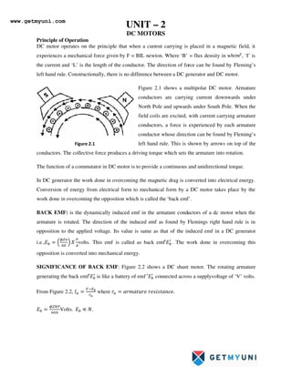
  • 1. Principle of Operation DC motor operates on the principle that when a current carrying is placed in a magnetic field, it experiences a mechanical force given by F = BIL newton. Where the current and ‘L’ is the length of the conductor. The direction of force can be found by left hand rule. Constructionally, there is no difference between a DC generator and DC motor. conductors. The collective force produces a driving torque which sets the armature into rotation. The function of a commutator in DC motor is to provide a contin In DC generator the work done in overcoming the magnetic drag is converted into electrical energy. Conversion of energy from electrical form to mechanical form by a DC motor takes place by the work done in overcoming the opposition which is called the BACK EMF: is the dynamically induced emf in the armature conductors of a dc motor when the armature is rotated. The direction of the induced emf as found by Flemings right hand rule is in opposition to the applied voltage. Its value is same as that i.e., volts. This emf is called as back opposition is converted into mechanical energy. SIGNIFICANCE OF BACK EMF generating the back emf′ is like a From Figure 2.2, where Volts. ∝ . Figure 2.1 UNIT – 2 DC MOTORS DC motor operates on the principle that when a current carrying is placed in a magnetic field, it experiences a mechanical force given by F = BIL newton. Where ‘B’ = flux density in wb/ is the length of the conductor. The direction of force can be found by left hand rule. Constructionally, there is no difference between a DC generator and DC motor. Figure 2.1 shows a multipolar DC motor. Armature conductors are carrying current downwards under North Pole and upwards under South Pole. When the field coils are excited, with current carrying armature conductors, a force is experienced by each armature conductor whose direction can be found by Fleming’s left hand rule. This is shown by arrows . The collective force produces a driving torque which sets the armature into rotation. The function of a commutator in DC motor is to provide a continuous and unidirectional torque. In DC generator the work done in overcoming the magnetic drag is converted into electrical energy. Conversion of energy from electrical form to mechanical form by a DC motor takes place by the work done in overcoming the opposition which is called the ‘back emf’. is the dynamically induced emf in the armature conductors of a dc motor when the armature is rotated. The direction of the induced emf as found by Flemings right hand rule is in opposition to the applied voltage. Its value is same as that of the induced emf in a DC generator volts. This emf is called as back emf′ . The work done in overcoming this opposition is converted into mechanical energy. SIGNIFICANCE OF BACK EMF: Figure 2.2 shows a DC shunt motor. The rot battery of emf ′ connected across a supplyvoltage of ‘ ! !#$%!. DC motor operates on the principle that when a current carrying is placed in a magnetic field, it = flux density in wb/' , ‘I’ is is the length of the conductor. The direction of force can be found by Fleming’s left hand rule. Constructionally, there is no difference between a DC generator and DC motor. shows a multipolar DC motor. Armature conductors are carrying current downwards under North Pole and upwards under South Pole. When the field coils are excited, with current carrying armature conductors, a force is experienced by each armature hose direction can be found by Fleming’s left hand rule. This is shown by arrows on top of the . The collective force produces a driving torque which sets the armature into rotation. uous and unidirectional torque. In DC generator the work done in overcoming the magnetic drag is converted into electrical energy. Conversion of energy from electrical form to mechanical form by a DC motor takes place by the is the dynamically induced emf in the armature conductors of a dc motor when the armature is rotated. The direction of the induced emf as found by Flemings right hand rule is in of the induced emf in a DC generator . The work done in overcoming this The rotating armature connected across a supplyvoltage of ‘V’ volts. www.getmyuni.com
  • 2. If is large, armature current will be less and vice versa. Hence acts like a governor i.e., it makes the motor self- regulating so that it draws as much current as required by the motor. VOLTAGE EQUATION OF A MOTOR: The voltage ‘V’ applied across the motor armature has to i) Overcome the back emf and ii) Supply the armature ohmic drop Hence ( ) …..1 This is known as voltage equation of DC motor. Multiplying both sides of voltage equation by ( ) ' …….2 ( !*!%#%* #$+ , -! !. ./ !*!%#%* !0 #1*!$ ,2 !%-$#%* +,3! 4!1!*,+!4 #$ -! !. ' ! %,++! *, CONDITION FOR MAXIMUM POWER Mechanical power developed by the motor is ./ ( 5 ' …….3 Condition for maximum power is 6 7 68 0 4. / 4 ( 5 2 0 ( 2 ( ) ' ' ………4 Thus the mechanical power developed by the motor is maximum when the back emf is equal to half the applied voltage. Figure 2.2 www.getmyuni.com
  • 3. TORQUE: Torque is the twisting moment about an axis. It is measured by the product of the force and the radius at which the force acts. Consider a pulley of radius ‘r’ metre acted upon a circumferential force of ‘F’ newton which causes it to rotate at ‘N’ rotations per second (r.p.s) as show in Figure. 2.3 T = F X r N-metre Work done by this force in one revolution = Force X Distance = F X 2π r joule. Power Developed = F X 2 π r X N joule/sec. = (F X r) 2π N joule/sec 2πN = angular revolution ω in rad/sec. And F X r = Torque ‘T’ Therefore Power Developed = T X ω joule/sec or watts…….. 5 ARMATURE TORQUE OF A MOTOR: Let Ta = armature torque in N –m developed by the armature of a motor running at N.rps. Therefore P = Ta X 2π N Watts …….. 6 Electrical equivalent of mechanical power developed Pm = ; 2 Ta = = ' 8 N – m ……....7 = 0.0162 8 kg-m ……..8 Also, on substituting for Eb i.e., ФZN ФZN ; 2 Therefore Ta = = ' Ф? N-mtrs Figure 2.3 www.getmyuni.com
  • 4. 26 Ta = 0.159 Ф Z N-mtrs …..9 =0.162 Ф Z kg-mtrs ……..10 (1 Kg = 9.81 N) From the above equation for torque, it is seen that (i) T Ф (ii) T∝ ' - For series motor (because Ф∝ ) before saturation. After saturation ; ∝ . (iii) ; ∝ - For shunt motor. (because Ф is constant in a shunt motor) SHAFT TORQUE (TSH): Some of the torque developed in the armature will be lost in supplying the iron and friction losses in the motor. The torque which is available for doing useful work is known as shaft torque ‘Tsh’. The horse power obtained by using the shaft torque is called as Brake Horse Power (BHP). BHP = @ABC ' DEF.F ………..11 Tsh = GH C DEF.F ' = IJKLJK M NKKO ' N-m Lost torque = ;−;OP = 0.159 X 8I 6 QMRKMI SIOOTO M UKKO N-mtrs ………12 = 0.162 X 8I 6 QMRKMI SIOOTO M UKKO kg-mtrs ………13 SPEED OF A DC MOTOR: = ( − Or ФZN = ( − N = Ф r.p.s N= K Ф N ∝ Ф ; ∝ ∅ ∅ = W,$$, if ∅ = constant, then ; ∝ ………….14 www.getmyuni.com
  • 5. 27 (i) For series motor, = ∝ X ФX N2∝ Y ФY where = = ( − = ' = ( − ' Y X = Y X 8X 8Y Or Y X = Y X ФX ФY ………..15 (ii) For shunt motor. ' = = ' = Ф= Ф' Ф = constant for shunt motor Ф1 = Ф2 Y X Y X ………….16 Speed regulation: is defined as the change in speed from No-load to full load when the rated load on the motor is reduced to zero, expressed as a percentage of rated speed. % speed regulation = ISI6OLTT6QJZZ ZI6OLTT6 QJZZSI6OLTT6 = 6 100 CHARACTERISTICS OF DC MOTORS: There are three important characteristics. 1. Armature torque vs Armature current ;vs (Electrical characteristics) 2. Speed vs armature current characteristic 3. Speed vs torque N vs; (Mechanical characteristics) CHARACTERISTICS OF SHUNT MOTORS i) @ 8 ii) 8 ###) @ N ; ; Figure 2.4 Figure 2.5 Figure 2.6 www.getmyuni.com
  • 6. 28 N α ∅ or N = h( 8i ∅ ) ; N = jk ∅ - jk8 ∅ ------- (a) @ jl∅ -------(b) Substituting (b) in(a) N = jk ∅ - jk jl∅Y ; --------- (17) m. nopq roCHARACTERISTICS For a shunt motor flux can be assumed practically constant (at heavy loads, decreases, due to increased armature reaction) ; ∝ ∅ ∅ = %,$$, ; ∝ Therefore electrical characteristic of a shunt motor is a straight line through origin shown by dotted line in Figure 2.4. Armature reaction weakens the flux hence ;1 characteristic bends as shown by dark line in figure 2.4, Shunt motors should never be started on heavy loads, since it draws heavy current under such condition. t. u pq roCHARACTERISTICS ∝ ; is practically almost constant. Hence the speed is constant. However, decreases slightly more than with increase in load and thus there is slight decrease in speed. This decrease in speed varies from 5 to 15% of full load speed and it depends on armature reaction and saturation. This characteristics is shown in Figure 2.5 v. u pq noCHARACTERISTICS This characteristic can be deduced from 1 and 2, shown in figure 2.6 www.getmyuni.com
  • 7. Performance curves of DC shunt motor The four essential characteristics of shunt motor i.e., torque, speed, current and efficiency plotted as a function of horse power are known as performance curves of the motor, shown in figure 2.7 Shunt motor has a definite No-load speed hence can be used where a load is suddenly thrown off with field circuit remaining close. The drop in speed from No-load to full load is small and hence referred to as constant speed motor. The efficiency curve is usually of the same shape for all motors and generators. It is advantageous to have an efficiency curve which is fairly flat and the maximum efficiency near to full load. Certain value of minimum current is required even when the output is zero as the input under No-load condition has to meet the losses within the machine. The shunt motor is also capable of starting under heavy load condition but the current drawn by the motor will be very high (; ∝ )compared to DC series motor. As the series motor draws only one and half times the full load current; ∝ ' , ∝ w;. CHARACTERISTICS OF SERIES MOTORS m. nopq ro CHARACTERISTICS ; ∝ ∅ ∅ ∝ ; ∝ ' – upto saturation ………. 18 ; ∝ – after saturation ………. 19 ; ; ;OP Figure 2.7 Figure 2.8 www.getmyuni.com
  • 8. 30 At light loads, and hence is small. But as increases ; increases as the square of the current up to saturation. After saturation becomes constant, the characteristic becomes a straight line as shown in Figure 2.8. Therefore a series motor develops a torque proportional to the square of the armature current. This characteristic is suited where huge starting torque is required for accelerating heavy masses. Ex. Hoists, electric trains, etc. t. u pq roCHARACTERISTICS ∝ ∅ # ++,x#!*y %,$$ ∝ = ∅ ………….20 If increases, ∅ increases and hence speed decreases. This characteristic is shown in figure 2.9(a). Change in for various load currents is small. Hence may be neglected. Therefore the speed is inversely proportional to flux, because ∝ ∅ . When the load is heavy, is large and speed is low. When the load is low, current and hence flux will be small. Therefore speed becomes dangerously high. Hence a series motor should never be started without load on it. v. u pq noCHARACTERISTICS ; ∝ # %,$$ Hence, ; ∝ . Therefore, N vs ;characteristic can be deduced from 1 and 2 as shown in Figure 2.9 (b) Figure 2.9 (a) ; Figure 2.9 (b) www.getmyuni.com
  • 9. PERFORMANCE CURVES OF DC SERIES MOTOR The performance curves of DC series motor are Figure 2.10. The machine is so designed that it is having maximum efficiency near rated load. For a given input current, the starting torque developed by a DC series motor is greater than that developed by a shunt motor. Hence series motors are used where huge starting torques are necessary. Ex. Cranes, hoists, electric traction etc. The DC series motor responds by decreasing its speed for the increased in load. The current drawn by the DC series motor for the given increase in load than DC shunt motor. The drop in speed with increased load is much more prominent in series motor than that in a shunt motor. Hence series motor is not suitable for applications requiring a constant speed. COMPOUND MOTOR CHARACTERISTICS Cumulative compound motors: characteristics are required and in addition the load is likely to be removed totally such as in some types of coal cutting machines or for driving heavy machine tools which have to take sudden deep cuts quite often. Speed will not become excessively high due to shunt winding and the motor will be able to take heavy loads because of series winding. Differential compound motors: Series field opposes the shunt field; therefore the flux is decreased as the load is ap motor. This results in the motor speed remaining almost constant or even increasing with increase in load. Summarizing, 1. 8 Lies between shunt ( = constant) and series ( characteristics as shown in figure 2.11 2. Used in rolling mills where light and heavy loads are thrown on the motor. PERFORMANCE CURVES OF DC SERIES MOTOR The performance curves of DC series motor are shown in Figure 2.10. The machine is so designed that it is having maximum efficiency near rated load. For a given input current, the starting torque developed by a DC series motor is greater than that developed by a es motors are used where huge starting torques are necessary. Ex. Cranes, hoists, electric traction etc. The DC series motor responds by decreasing its speed for the increased in load. The current drawn by the DC series motor for the given increase in load is lesser than DC shunt motor. The drop in speed with increased load is much more prominent in series motor than that in a shunt motor. Hence series motor is not suitable for applications requiring a constant speed. COMPOUND MOTOR CHARACTERISTICS are used where series characteristics are required and in addition the load is likely to be removed totally such as in some types of coal cutting machines or for driving heavy machine tools which have to take sudden deep ten. Speed will not become excessively high due to shunt winding and the motor will be able to take heavy loads Series field opposes the shunt therefore the flux is decreased as the load is applied to the motor. This results in the motor speed remaining almost constant or even increasing with increase in load. = constant) and series (∅ ∝ ) in figure 2.11. rolling mills where light and heavy loads are thrown on Figure 2.10 Figure 2.11 shunt motor. Hence series motor is not suitable for applications requiring a constant speed. Figure 2.10 Figure 2.11 www.getmyuni.com
  • 10. 3. Cumulative compound motor has a finite No-load speed and has a load – relieving characteristics of a series motor under heavy load conditions. 4. Differential compound motors are seldom used in practice.(because of rising speed characteristics) SPEED CONTROL OF DC MOTORS DC motors are in general much more adaptable speed drives than AC motors. Speed of a DC motor can be controlled in a wide range. h ∅ h 8g ∅ Since armature resistance drop is small, N = h ∅ ………….21 From the above equation, two methods of speed control are possible. 1. Variation of field current which varies the flux/pole (Ф) and is known as field control. 2. Variation of terminal voltage ‘V’ known as armature voltage control. FIELD CONTROL: For a fixed terminal voltage, Y X ФX ФY 8{X 8{Y (for linear magnetization) …………..22 Limitations of speed control by field control: 1. ‘N’ below rated speed is not possible. Because Ф can be decreased and cannot increase. 2. N∝ = Ф ; ∝ } for a given armature current, this method suits for constant kW drives only where ‘T’ decreases if speed decreases. 3. Not suited for speed reversal. DC SHUNT MOTOR: N = jk Ф 5 jk jlФY T ………23 Figure 2.13 Figure 2.12 www.getmyuni.com
  • 11. Speed control is achieved by means of a rheostat in the field circuit as shown in the Figure 2.12. The speed torque characteristics have a small linear drop due to the second term (ra effect) in the above equation. The field is weakened due to the armature reaction. The working range of the speed torque characteristics reduces with increasing speed in order for the armature current not to exceed the full load value with a weakening field. The speed – torque curves are shown in Figure 2.13 DC SERIES MOTOR: Speed control is achieved by adjusting the field ampere turns. There are three ways for varying the field ampere turns. 1. DIVERTER FIELD CONTROL: Diverter resistance Rdis connected across the field winding as shown in Figure 2.14. By varying Rd the field current and hence the field ampere turns can be reduced. Therefore, the field current is given by If = Ia i~ i~ iA€ KdIa……24 Where Kd = i~ i~ iA€ Kd = = = A€ ~ We know that, for series motor N = 8( A€) Ф And T 0∝ Ф or T = h@Ф T = h@h‚ ' , Ia = ƒ @ jlj{ If there is no Rd, then Ф = h‚ N = h „ Ф 5 8( ) Ф † N=KN‡ j{8 √@( A€) wjlwj{ .j{ √l w‰lƒ‰{ Š Figure 2.14 www.getmyuni.com
  • 12. N = jk j{ „ 8 5 ( ) OT)† …….25 If Rd is introduced then, Ф = KdKf Ia. Therefore N = h „ Ф 5 8( A€) Ф † KN‹ j~j{8 5 8( A€||i~) j~j{8  Substituting ƒ @ j~j{ N jk j{ ‹ wj{jl √@wj~ 5 (  A€||i~) j~  ………..26 From the above equation speed torque characteristics for decreasing values of Kd are plotted which is shown in above Figure 2.15. 2. Tapped field control: The field ampere turns are adjusted in steps by varying the number of turns included in the circuit as shown in figure 2.16, the following relations are obtained from the circuit. AT (effective) = A€ | A€ Ia = hOT Therefore Ф = h‚hOT ………… 27 Decreasing Kd N T Figure 2.15 Figure 2.16 www.getmyuni.com
  • 13. Nse | = turns with rse | = Kserse T = h‚hOThK ' ƒ @ jlj{jA€ ………28 From equation 25, N = jk j{ „ 8 5 () OT)† Substituting ƒ @ jlj{jA€ , N = jk j{ ‹ wjlj{jA€ √@ 5 ( ) hOTOT) The speed torque characteristics are shown in figure 2.17 and are of similar to those of diverter field control. 3. Series parallel control: In this method, the field windings are divided into two equal halves and then connected in series or parallel to control the field ampere turns as shown in figure 2.18 and 2.19 respectively. 2 A€ ' 8 ' = AT parallel …………. 30 AT parallel = = ' (Ž;!#!) ………. 31 Ф = = ' h‚ Kse = 1 or = ' i.e., only two speeds are possible; parallel field connection gives the higher speed, series field connection gives the lower speed. Decreasing Kse N T Figure 2.17 Figure 2.18 Figure 2.19 www.getmyuni.com
  • 14. COMPARISION OF TORQUE DEVELOPED BY MOTORS IN SERIES AND PARALLEL CONNECTION: MOTORS IN SERIES: ∝  Y 8 ∝ '8 ………… 32 This speed is 1/4th of the speed of the motor, when in parallel. T ∝ ФI ∝ ' ………... 33 Torque is four times that produced by motors when in parallel. MOTORS IN PARALLEL:  Ф  (!#! ,,) Since ≅ (; ∝ ’ Y ∝ ' 8 ; Torque Ф I ∝ ' ; Therefore T ∝ 8 ' ' ; T ∝ 8Y “ ……… 34 From equations 33 and 34 torque developed in series connection is four times that of motors in parallel connection. ARMATURE VOLTAGE CONTROL: In this method, applied voltage across the armature of the DC motor is varied. This method is superior to field control in the following aspects: 1. This method provides a constant torque drive.(if the Ф and Ia are maximum, maximum torque can be obtained as T Ф ) 2. Since main field ampere turns are maintained at large value, flux density distortion caused by armature reaction is limited. 3. Unlike field control scheme, speed reversal can be easily implemented. This method requires a variable voltage supply which makes this method costlier. DC SHUNT MOTOR: Following are the armature control schemes for DC shunt motor. 1. Rheostatic control: Figure 2.20 Figure 2.21 www.getmyuni.com
  • 15. Here the applied armature voltage is varied by placing an adjustable resistance ‘R’ in series with the armature as shown in the Figure 2.22. N vs T for varying ‘R’ is shown in figure 2.23. Some of the limitations of the rheostatic method are: 1. Speeds only below rated speed 2. Range of speeds is limited because efficiency reduces drastically for large speed reductions η/ ( (( 5 T) ( 1 5 T ( 3. Speed regulation is poor. Because for a given resistance re, N varies directly with load. Therefore this method is suitable for very small (fractional kW) or for short-time, intermittent slowdowns for medium sized motors. I ∝ (5I = ∝ (- ( ) ”) ( 5 ( ) ”) ( 5 ( 5 ( ) ”) ( The load current for which N= 0 is 0 = 1 5 8Xi• 0 1 5 8Xi• ; 8Xi• 1 ; = i• ……… 35 This is the maximum current and is the No-load speed shown in figure 2.24 N Ia N0 Figure 2.22 Figure 2.23 Figure 2.24 www.getmyuni.com
  • 16. 1. Shunted armature control: In the armature rheostatic control method, the change in armature current due to change in load will affect the speed. Hence in this method the armature is shunted by an adjustable resistance as shown in Figure 2.25. Advantages of this method are a. Speed regulation will be better. b. The changes in the armature current due to load will not be as effective as the armature is connected across a resistance. SERIES PARALLEL CONTROL OF SHUNT MOTOR: In this method the two identical motors are coupled together mechanically to a common load. Two speeds at constant torque are possible in this method – one by connecting motor armature in series and the other by connecting them in parallel as shown in figures 2.26 and 2.27 respectively. When connected in series the voltage across each motor is half the supply voltage and when in parallel, each armature carries full supply voltage. This method is superior to rheostatic control so far as efficiency is concerned but the speeds that can be obtained can only be two steps. This method is commonly employed for speed control of series traction motors. Figure 2.25 Figure 2.26 Figure 2.27 www.getmyuni.com
  • 17. WARD-LEONARD METHOD OF SPEED CONTROL: It is a combined armature and field control and is therefore operationally the most efficient method of speed control with a wide range. ‘M’ is the main motor whose speed control is required. The field of this motor is permanently connected across the DC supply lines. Its armature is supplied by a variable voltage derived by a polyphase Induction Motor-DC generator set. The field of the DC generator is excited from an exciter coupled to the extension of the induction motor shaft. The entire arrangement is shown in the figure 2.28. The reversible switch provided for the generator makes it possible to easily reverse the generator excitation thereby reversing the voltage polarity for reversing the direction of rotation of motor. Though expensive, this arrangement can be easily adapted to feedback schemes for automatic control of speed. This method provides both constant torque and constant HP (or kW) drive. The motor armature and its field winding are fed at maximum values at the base speed Nbase. Reducing armature voltage provides a constant torque speed control where the speed can be reduced below the base value, while the motor has full torque capability. For obtaining speeds above Nbase the field is gradually weakened. The motor torque therefore reduces as its speed increases which corresponds to constant kW (or HP) drive. This is shown in the Figure 2.29. Figure 2.28 Figure 2.29 www.getmyuni.com
  • 18. 40 Some of the features of the Ward Leonard system are given below: 1. Absence of external resistance improves efficiency at all speeds and also when the generator emf becomes less than the back emf of the motor, the electrical power flows back from motor to generator, is converted to mechanical form and is returned to the mains via the driving AC motor. 2. Motor starts up smoothly therefore No starting device is required. 3. Speed reversal is smoothly carried out. 4. Fine speed control from zero to rated value in both the directions. This method of speed control is used in a. High speed elevators b. Colliery winders Advantages 1. Absence of external resistance improves efficiency at all speeds 2. Motor starts up smoothly. No starting device is required 3. Speed reversal is smoothly carried out STARTERS FOR DC MOTORS Necessity of starter: The current drawn by the armature is given by i . At starting, 0 because N = 0. Armature resistance will be very low. Therefore, the current drawn by the motor will be very high. In order to limit this high current, a starting resistance is connected in series with the armature. The starting resistance will be excluded from the circuit after the motor attains its rated speed. From there on back emf limits the current drawn by the motor. The arrangement is shown in the figure 2.30 which is a three point starter for shunt motor. Three Point Starter: It consists of resistances arranged in steps, ”=to ”Fconnected in series with the armature of the shunt motor. Field winding is connected across the supply through a protective device called ‘NO – Volt Coil’. Another protection given to the motor in this starter is ‘over load release coil’. The arrangement is shown in Figure 2.30 30 www.getmyuni.com
  • 19. To start the motor the starter handle is moved from OFF position to Run position gradually against the tension of a hinged spring. An iron piece is attached to the starter handle which is kept hold by the No-volt coil at Run position. The function of No volt coil is to get deenergised and release the handle when there is failure or disconnection or a break in the field circuit so that on restoration of supply, armature of the motor will not be connected across the lines without starter resistance. If the motor is over loaded beyond a certain predetermined value, then the electromagnet of overload release will exert a force enough to attract the lever which short circuits the electromagnet of No volt coil. Short circuiting of No volt coil results in deenergisation of it and hence the starter handle will be released and return to its off position due to the tension of the spring. In this type of starter, the shunt field current has to flow back through the starter resistance thus decreasing the shunt field current. This can be avoided by placing a brass arc on which the handle moves as shown in Figure 2.31. Figure 2.30 Figure 2.31 www.getmyuni.com
  • 20. FOUR POINT STARTER: Figure 2.32 shows a four point starter. One important change is the No Volt Coil has been taken out of the shunt field and has been connected directly across the line through a Protecting resistance ‘R’. When the arm touches stud one. The current divides into three paths, 1. Through the starter resistance and the armature, 2. Through shunt field and the field rheostat and 3.Through No-volt Coil and the protecting resistance ‘R’. With this arrangement, any change of current in shunt field circuit does not affect the current passing though the NO-volt coil because, the two circuits are independent of each other. Thus the starter handle will not be released to its off position due to changes in the field current which may happen when the field resistance is varied. Application of DC Motors: DC Series Motor: 1. Starting torque is very high up to the five times the full load torque. 2. Speed regulation of the DC series motor can be varied widely. 3. Are used in hoists, cranes, battery powered vehicles, electric traction, etc. DC Shunt Motor: 1. Has a medium starting torque. 2. Speed regulation is 5 to 15%. Figure 2.32 www.getmyuni.com
  • 21. 43 3. It is essentially used for constant speed applications requiring medium starting torques such as centrifugal pumps, fans, blowers, conveyors, machine tools, printing presses etc. DC Compound Motor: 1. Its characteristics depend on degree of compounding. 2. It has considerably high starting torque and drooping speed - load characteristics. 3. Used for varying loads such as shears, conveyors, crushes, punch presses, hoists, rolling mill, milling machines etc. PROBLEMS: 1. A 250 V DC shunt motor has shunt field resistance of 150 Ω and armature resistance of 0.6 Ω. The motor operates on No-load with a full field flux at its base speed of 1000 rpm with armature current of 5Ž. If the machine drives a load requiring a torque of 100Nm, calculate the armature current and speed of motor. If the motor is required to develop 10 kW at 1200 rpm, what is the required value of the external series resistance in the field circuit? Neglect saturation and armature reaction. SOLUTION: We know that, h Ф ™/ h ™/ ; hФ h; At No-load; 250 − 5 0.6 h ' C = Or K = 2.36 When driving a load of 100 Nm, ; h 100 2.36 42.4 Ž Now, ™/ j 'F “'.“ C . '.E 95.15rad/s; $ ' ™/ 909 + Given: Output = 10 kW at 1200 rpm Assuming linear magnetization, it can be written as h ‚™/; ; h ‚ ; From the data of No-load operation ‚ 'F =F 1.67 Ž; h j 8{ '.E =. D 1.413; Now250 − 0.6 g 10 1000 Solving 44.8 Ž (the higher value is rejected) www.getmyuni.com
  • 22. 44 Substituting the values in the above equations, 250 − 0.6 44.8 1.413 ‚ 2 1200 60 Or ‚ 1.257 Ž Therefore ”‚(,*) 'F =.'FD 199 Ω Hence ”‚(!x!$*) 199 − 150 49 Ω. 2. A 4-pole series wound fan motor draws an armature current of 50A, when running at 2000 rpm on a 230 V DC supply with four coils connected in series. The four field coils are now connected in two parallel groups of two coils in series. Assuming the flux/pole to be proportional to the exciting current and load torque proportional to the square of speed, find the new speed and armature current. Neglect losses. Given: Armature resistance = 0.2 Ω, resistance of each field coil = 0.05 Ω. SOLUTION: hOT$ ;S hS$' ;Ÿ hŸOT; Field coils in series;OT ;”OT 4 0.05 0.2 Ω, ” 0.2 Ω ” 0.2 + 0.2 0.4 Ω ; = 50 Ž = 230 − 0.4 50 210 ( 210 h 50 2000 hS (2000g' hŸ (50g' Field coils in two series group in parallel OT!22!%#1!g = ”OT 2 0.05 2 0.05 Ω ” 0.2 + 0.05 0.25 Ω ' 230 − 0.25 ' h ' 2 ¡ $' hS$' ' hŸ ' 2 ¡ ' From the above equations, www.getmyuni.com
  • 23. 45 $' ' (2000g' ' ' 2 (50g' If $' 28.3 ' From the equations, we have 230 5 0.25 ' 210 '$' 2 50 2000 Substituting for $' ' ' + 8.4 ' 5 7740 0 ' 83.9 Ž; #£$,#$£ $!£#1! 1* ! $' 28.3 83.9 2374 + 3. A shunt motor runs at 1200 rpm on a 420 V circuit and current taken in 30 A in addition to the field current. What resistance must be placed in series with armature in order that the speed may be reduced to 600 rpm, the current through the armature remaining same.ra = 3Ω given. SOLUTION: Y X Y X N1 = 1200 rpm; N2 = 600 rpm Eb1 = 420 – 30 x 3 =330 V; Eb2 = 420 – 30 Rt =' = “' E i• EE ; Rt = 8.5 Ω Rex = Rt – ra = 8.5 – 3 = 5.5 Ω 4. A 4 pole 230 V series motor runs at 1000 rpm when the load current is 12 A. the series field resistance is 0.8 Ω and the armature resistance is 1Ω. The series field coils are now regrouped from all in series to two in series with two parallel paths. The line current is now 20 A if the corresponding weakening of field is 15 %. Calculate the speed of the motor. SOLUTION: Y X Y X ∅X ∅Y Eb1 = 230 – 12 x 1.8 = 208.4 Eb2 = 230 – 20 1 + .“ ' = 206 V ' 1000 206 208.4 1 0.85 ' 1163 +. www.getmyuni.com
  • 24. 46 5. A 220 V DC shunt motor runs at 500 rpm when the armature current is 50 A calculate the speed if the torque is doubled. Given ra = 0.2 Ω. SOLUTION: Ta α Ф Ia Ta2 = 2 Ta1 Therefore @Y @X 2 8Y 8X @Y @X Ia2 = 100 A Using Eb= V- Iara Eb2 = 200 V Eb1 = 210 V ' = ' = N2 = 476 rpm. 6. A 500 V, 50 BHP (37.8 kW) 1000 rpm DC shunt motor has, on full load an η of 90%. The armature circuit resistance is 0.24 Ω and there is a total voltage drop of 2 V at the brushes. The field current is 1.8 A. Determine (i) Full load line current (ii) Full load shaft torque (iii) Total resistance in motor starter to limit the starting current to 1.5 times the full load current. SOLUTION: (i) motor input = ED.¤ C = .¥ = 41444 W Therefore full load line current = “=“““ F = 82.9 A (ii) Tsh = IJKLJK M NKKO ' = 356 N-m (iii) Starting line current = 1.5 X IFL = 124.3 A Ia at starting = 124.3 – 1.8 = 122.5 A Let R = Starter Resistance 122.5 (R+0.24) + 2 = 500 V R = 3.825 Ω. www.getmyuni.com
  • 25. 47 7. A 460 V series motor runs at 500 rpm taking a current of 40 A. Calculate the speed and % change in torque if the load is reduced, so that the motor is taking 30 A. Total resistance of the armature and field circuit is 0.8 Ω. Assume flux is proportional to the field current. SOLUTION: Ф α Ia, Ta α Ф Iaα Ia 2 @Y @X ¥ = % change in torque = @Y@X @X 100 = 43.75% Using Eb = V – Iara, Eb1 = 428.6 V, Eb2 = 436 V. Y X Y X 8X 8Y , N2 = 679 rpm. 8. A 220 V DC series motor is running at a speed of 800 rpm and draws 100 A. Calculate at what speed the motor will run when developing half the torque. Armature + field resistance is 0.1 Ω. Assume that magnetic circuit is unsaturated. SOLUTION: Y X Y X 8X 8Y Ф α Ia, Ta α Ф Ia α Ia 2 T1α Ia1 2 T2α Ia2 2 Ia2 = 70.7 A Using Eb = V – Iara Eb1 = 210 V, Eb2 = 212.9 V Y X Y X 8X 8Y =N2 = 1147 rpm. 9. An 8kW 230 V, 1200 rpm DC shunt motor has ra = 0.7Ω. the field current is adjusted until, on NO load with a supply of 250 V, the motor runs at 1250 rpm and draws a armature current of 1.6 A. A load torque is then applied to the motor shaft, which causes the armature current to raise to 40 A and the speed falls to 1150 rpm. Determine the reduction in flux per pole due to the armature reaction. SOLUTION: N α Ф or N = h 8 Ф or Ф = h 8 Ф (no load) = 0.2 KN Ф (load) = 0.193 KN Reduction in flux/pole due to armature reaction = .' .=¥E .' 100 = 3.5% www.getmyuni.com
  • 26. 48 10. A 230 V, DC shunt motor runs at 800 rpm and takes armature current of 50 A. Find the resistance to be added to the field circuit to increase the speed from 800 rpm to 1000 rpm at an armature current of 80 A. Assume the flux to be proportional to the field current. Given ra = 0.15Ω and rf = 250Ω. SOLUTION: If1 = { = 'E 'F = 0.92 A, Ia = 50 - 0.92 = 49.08 A Using Eb= V – Iara; Eb1= 222.64 V ; Eb2 = 218 V Ф α If, If2 = {  i taking rf + R = Rt, and using Y X Y X . 8{X 8{Y ; Rt = 250 + R = 319 Ω; R = 69Ω. www.getmyuni.com
  • 27. SPECIAL MACHINES SPECIAL MACHINES SPECIAL MACHINES SPECIAL MACHINES Permanent magnet D.C motors: Permanent magnet D.C motors: Permanent magnet D.C motors: Permanent magnet D.C motors: These are same as that of ordinary D.C shunt motors, but the difference is they have permanent magnets instead of stationary field winding for producing the required magnetic flux. Construction: The Figure 2.33 and 2.34 Shows the construction of a permanent magnet D.C motor. The magnetic frame or yoke supports the permanent magnet also produces the return path for magnetic flux. The armature consists of slot for windings, commutatorsegments brushes are same as those in conventional D.C motors. The magnets are made of materials like ferrite, alnico, iron-cobalt, etc. These materials have high residual flux-density, high energy output. These materials also have good mechanical properties. Working performance characteristics: Working performance characteristics: Working performance characteristics: Working performance characteristics: The equivalent circuit of a permanent magnet D.C motor is shown in Figure 2.35 Ra= Arm resistance; field windings are absent of permanent magnets. Figure 2.33 Figure 2.34 Figure 2.35 www.getmyuni.com
  • 28. 50 Ф Ф ; n- is in rps = Eb= Ф X ' ' = Ф Ä ' Therefore, Eb= ' ω ФorEb= K X ФX ω ………… 36 T = ' ФZIa or T K ФIa -- in conventional motors. In case of permanent magnet D.C motors, The resistant flux Ф is constant. Eb KФω or Eb Kpω where Kp K.Ф Kp Ä Torque T 8 Ä KpIa because Ä Kpg V Eb+IaRa Kpω+IaRa. Therefore ω 8i jÊ …………….. 37 www.getmyuni.com
  • 29. Performancecharacteristics: Performancecharacteristics: Performancecharacteristics: Performancecharacteristics: Torquev/s speed is almost linear. Therefore they are used in servo motors. Efficiency is better than conventional motors. Therefore field losses are absent. Because ofconstant flux, speed control is not possible with flux control method. Therefore only Armature control can be employed hence the speeds obtained will be below the normal speeds. Advantages: Advantages: Advantages: Advantages: 1. No external Excitation is required to produce the flux. Therefore less losses efficiency is high. 2. As field windings are absent, their size is smaller, cost decreases. 3. Motors designedupto 12V or less produce less TV radio interference. 4. Less noise. Disadvantages: Disadvantages: Disadvantages: Disadvantages: 1. If the Armature reaction is more because of high armature current, permanent magnet may get demagnetized. Temperature may also affect the same. 2. The flux density produced in the air gap by the permanent magnet is limited. 3. Speeds above normal speeds are not possible. Figure 2.36 www.getmyuni.com
  • 30. 52 Applications: Applications: Applications: Applications: 1. These motors normally run on 6V,12V, or 24V D.C supply. 2. They are extensively used in automobiles. 3. They are used in blowers, heaters air conditions. 4. They are used for disc drives in personal computers. 5. They are used in fans, radio antennas, marine engine starters, wheel chairs cordless power tools, vacuum chamber, mixer etc. 6. They are available upto a rating of 150KW. PROBLEM PROBLEM PROBLEM PROBLEM: : : : 1g A permanent magnet D.C motor has resistance of 1Ω, the speed of the motor is 2000rpm when fed from 50V D.C source while taking 1.2A determine ig No load rotational losses. iig The motor output when running at 1800rpm when source voltage is 48V. iiig Stalling torque when fed from 20V source. SOLUTION: SOLUTION: SOLUTION: SOLUTION: Eb V-Iara 50 - 1.2 1 48.8V ig At no load, no load losses EbIa 48.8g 1.2g 58.56 W. iig Eb Kp.ω, Kp Eb/ω 48.8/2π2000/60g 0.2330V-S/rad. For a speed of 1800rpm, ω 2πN/60 2π 1800g/60 188.49 rad/s. Therefore Eb Kp.ω 0.2330g 188.49g 43.91V Ia V -Eb/ra 48 – 43.91/1 4.09A Power developed EbIa 43.91g 4.09g 179.59 W Motor output EbIa- Rotational losses 179.59 – 58.56 121.03 W iiig Eb 0 when motor stalls, V Iara Therefore Ia V/ra 20/1 20A Stall torque KpIa 0.2330g 20g 4.66 N-m www.getmyuni.com
  • 31. Brushless DC Motor: Construction of brushless DC motor: The construction of brushless DC motor is shown in Figure 2.37.It consists of a stator and a permanent magnet rotor. The stator houses a polyphase winding in its slots. The rotor consists of permanent magnets. The stator windings are fed by an inverter. Rotor position sensors generate pulses for controlling the transistors in the inverter. There are 2 types Brushless DC Motor 1. Unipolar or half wave Brushless DC Motor Figure 2.37 Figure 2.38 www.getmyuni.com
  • 32. In this type, rotor consists of optical sensors. The optical sensor has a light source, three phototransistors P1, P2 and P3 mounted on the end plate of the motor separated by 1200 from each other and a revolving shutter coupled to the shaft of the motor. The optical sensor is shown in Figure 2.38. The stator, two pole rotor and driving circuit used to excite the stator winding are shown in Figure 2.39. When the light falls on P1 it actuates the transistor Q1 and a pulse (Pl1) appears across Ph1 (phase 1) and creates a magnetic pole say North. The south pole of the rotor is attracted by this Ph1 and the rotor aligns with it. As the revolving shutter is coupled to shaft of the rotor, the light falls on P2 actuating transistor Q2 resulting in a pulse (Pl2) appearing across Ph2. This pulse creates a pole and the rotor is attracted by this Ph2. In this way, the rotor rotates in Uni-polar brushless DC motor. Figure 2.39 Figure 2.40 www.getmyuni.com
  • 33. 2. Bipolar Brushless DC Motor Figure 2.41 shows the bipolar brushless DC motor. In the motors of higher ratings the inductive energy due to the windings will be high. This motor uses three phase inverter with feedback diodes to return the inductive energy to the supply. The rotor uses Hall effect sensors to sense the rotor position. The hall sensors are 1200 electrical from each other. Switching of each transistor occurs in response to rotor position sensor. Transistors are triggered in sequence. A pair of transistor conducts for 1200 . Torque reversal is achieved by the shifting the base drive signal by 1200 . This motor is suitable for high performance servo drives and also for ratings higher than 100 Watts. Features of brushless DC motor: i) Due to absence of brushless commutator they require practically no maintenance. ii) The operation is highly reliable and they have long life. iii) They have low inertia friction. iv) Low radio frequency interference hence the operation is noiseless. v) Speeds upto 30000rpm more is possible. vi) Cooling is much better. vii) Due to feed back diodes efficiency is high (75-80%). Applications of brushless DC motor: i) Unipolar brushless DC motor upto 100W, table driver, record players, spindle drives in H D drives, video recorders control systems. ii) Also in aerospace, gyroscope biomedical instruments. Figure 2.41 www.getmyuni.com