This document discusses the design calculation of a three-phase self-excited induction generator driven by a wind turbine. It presents the dq-modeling approach for transient state analysis of the induction generator and includes calculations of total impedance regulation, required capacitance for excitation, efficiency, and torque required to drive a 3.6 kW induction generator. The calculations are based on parameters of the 3.6 kW generator including stator and rotor resistances and inductances. Equivalent circuits are presented and curves of total impedance, capacitance, and efficiency versus slip are shown based on simulations in Matlab. The generator is most efficient when operating between slip values of -0.055 and -0.1, corresponding to rotor speeds of
2. International Journal of Trend in Scientific Research and Development (IJTSRD) @ www.ijtsrd.com eISSN: 2456-6470
@ IJTSRD | Unique Paper ID – IJTSRD26728 | Volume – 3 | Issue – 5 | July - August 2019 Page 1432
Rotor winding inductance L2 = 0.012 H
Nominal torque = 50 Nm
Number of pole P = 6
Magnetizing inductance Lm = 0.181 H
Rotor inertia J = 0.045 kgm2
So, the synchronous speed 1000
6
50120
s
n
rpm
For rotor speed is vary from 1000 rpm to 2000 rpm, the p.u
slip is vary 0 to -1.
For convenient analysis is obtained let the slip value in
matrix form such as;
s =[-0.00001,-0.008,-0.035,-0.055,-0.1,-0.12,-0.15,-0.18,-0.2,-
0.22,-0.24,-0.27,-0.3,-0.4,-0.5,-0.6,-0.7,-0.8,-0.9,-1]
2b2a
b
1Xj
2b2a
a
1RZ
where,
11 fL2X ; 220 fL2X ; mm fL2X
So, X1 = 3.7699 Ω , X20 = 3.7699 Ω and Xm = 56.863 Ω.
The rotor reactance is depend on the slip of generator, X2 =
sX20.
At s = -0.1, -0.37699 Ω;
Where,
s = 1.3497˚
And
2
2
2
2
2 X
s
R
Z
= 16.0044 Ω
From Equation 4.4;
2
Z
2θcos
a = 0.0625,
2Z
2θsin
mX
1
b = 0.0191
Then, the magnitude of total impedance is;
2
221
2
221
ba
b
X
ba
a
RZ
= 18.215 Ω
The phase angle of the total impedance; 26.913˚
18.215 26.913Z Ω =16.233+j8.24
By using Equations 4.34 to 4.38, the following data are
obtained for various slip under generator operation.
Efficiency calculation of 3.6 kW SEIG;
Core losses Rm can be determined by making the machine
rotate experimentally at no load and measuring the active
power per phase Po, the average voltage per phase Vo, and
the average current per phase Io. So, the 3.6 kW SEIGismade
to turn at the synchronous rotation (s = 0), to allow
separation of the mechanical losses from the total losses. In
practical, the data of P0, V0 and I0 are difficult to obtain.
Therefore, assume nearly values of these variables as
following to get convenient calculation.
P0 = 275 W; V0 = 400 3 V; I0 = 6.29 A
Then, from Equation 4.10,
1
2
oo
2
o
m
RIP
V
R
= 251.932 Ω
Taking load power such as; PL = [1000, 1200, 1400, 1600,
1800, 2000, 2200, 2400, 2600, 2800, 3000, 3200, 3400,
3600] W at 0.9 power factor lagging. So,
25.8420.9cosp.fcosθ 11
For load power 1.8 kW at F = 0.7 p.u;
From Equation 4.47,
2
ph
LP
L
V
R
FP
= 42.328 Ω and
From Equation 4.46,
LP
LP
R
X
F tan
124.852 Ω
From Equation 4.45,
2 2
LP LP
L 2 2 2
LP LP
F X R
R
R F X
= 34.286;
2
LP LP
L 2 2 2
LP LP
R X
X
R F X
= 23.722 Ω
22
L L LZ R FX = 114.2857 Ω
And for unity power factor compensation, Xc = XL But,
Xc = LP
LP
X X
X X
= 35.0372 Ω;
C =
cXfπ2
1
= 90.85 μF;
2X1X
2
2X1X
2
Fs
2R
F
1R
pX
= 128.118Ω;
s
2R
1R
2
2X1X
2
Fs
2R
F
1R
pR
= - 30.1872 Ω;
mL m LP
1 1 1
R R R
= 0.0349;
RmL = 81.4787 Ω;
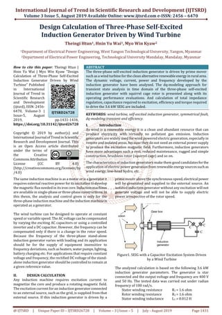
Figure2. Equivalent Circuit of the Parallel Loaded
Induction Generator
3. International Journal of Trend in Scientific Research and Development (IJTSRD) @ www.ijtsrd.com eISSN: 2456-6470
@ IJTSRD | Unique Paper ID – IJTSRD26728 | Volume – 3 | Issue – 5 | July - August 2019 Page 1433
s
s1
1.6F3.393j3.2
ph
V
2
I
= 23.2361A
s
s1
2R2
2I
mR
2
phV
2R1R2
2I
s
s1
2R2
2I
η
= 76.4954 %
Torque calculation,
The expression for electromagnetic torque for generator
operation, in terms of the arbitrary reference variables is:
From Equation 4.19,
drqsqrdsme iiiiL
2
P
2
3
T
For 3.6 kW SEIG,
Magnetizing inductance (Lm) = 0.181H
Rotor inertia (J) = 0.045 kgm2;
ids = 11.7A; idr = -13.4A; iqs = 0A; iqr = -11.6A
So, Te =
3
0.181 11.7 11.6 0
2 2
P
= -110.54394 Nm
And the torque and speed for the generator operation are
related by the following expressions:
eTrpω
2
P
JDT
110.54394s)(1
s
ω
ds
d
2
4
0.045 ;
Where,
ωs = 100 rad/s and
TD = -1492.3432 Nm
III. SIMULATION AND RESULTS
The following curveis drawn byMatlabprogramapplication.
In Figure 3, the total impedance is decreased after generator
speed is greater than its synchronous speed. The total
impedance is smallest between -0.4 and -0.8 p.u of the slip
value.
Figure3. The Total Impedance / Slip Curve of 3.6 kW SEIG
Figure4. Capacitance / Frequency of 3.6 kW SEIG
Figure5. The Capacitance / Load Curve of 3.6 kW SEIG
Figure 4 and Figure 5 are drawn by Matlab application., The
capacitance required for the SEIG is increased as generator
supplied load and F are increased.
Figure 6.The Efficiency / Slip Curve of 3.6 kW SEIG
Figure7. The Efficiency / Rotor Reactance Curve of 3.6 kW
SEIG
The curves are drawn by Matlab program application in
Figures 6 and 7 In Figure 6, the efficiency is negative when
slip is in -0.00001 (i.e generator speed is in 1010 rpm). And
the efficiency is higher when the slip is between -0.055 and-
0.1. So, the SEIG must be generated electricalpowerwith the
prime mover speed between 1020 and 1200 rpm. From
Figure 7, the efficiency is higher when the rotor reactance is
between -6.3 Ω and -8 Ω.
4. International Journal of Trend in Scientific Research and Development (IJTSRD) @ www.ijtsrd.com eISSN: 2456-6470
@ IJTSRD | Unique Paper ID – IJTSRD26728 | Volume – 3 | Issue – 5 | July - August 2019 Page 1434
IV. DISCUSSION AND CONCLUSION
Power absorbed by a wind turbine is proportional to the
cube of the wind speed. Wind turbines are designed to yield
maximum output power at a given wind speed. In case of
stronger wind, it is necessary to waste part of the excess
energy of the wind in order to avoid damaging the wind
turbine.
At a particular speed the capacitance required for self-
excitation, when the machine operates atnoload,is less than
the capacitance required forself-excitationwhenitis loaded.
When an induction machine operates as a motorthespeed of
the rotating air gap magnetic fieldis totallydependentonthe
excitation frequency. However, in the SEIG, it is shown that
the frequency of the generated voltagedepends onthespeed
of the prime mover as well as the conditionoftheload.When
the speed of the prime mover drops with load, then the
decrease in voltage and frequency will be greater than for
the case where the speed is held constant.Keepingthespeed
of the prime mover constant with increased load causes the
magnitude of generated voltage and frequency ofanisolated
SEIG to decrease. .
When the speed of the prime mover is varied thefluxlinkage
in the induction generatoris variedinversely proportionalto
the rotor speed so that the generated voltage will remain
constant. Once a constant DC voltage is achieved a DC load
can use it directly or, if required, it is a matter of having an
inverter to produce a constant voltage and frequency AC
output. Different types of vector control techniques are
developed to control the excitation and the active power
producing currents independently. That is, the current
control scheme causes the currents to act in thesameway as
in a DC generator where the field current and the armature
current are decoupled.
The analysis and explanations presented in this thesis
provide a good foundation for further research in thearea of
isolated induction generators driven by a wind turbine. By
studying this thesis, it can get not only the basic principle of
induction generator theory butalsothesimulationmodelfor
SEIG. Therefore, this thesis will help to develop the
technology in the renewable energy sources in Myanmar.
REFERENCES
[1] Godoy Simoes. M and Felix A. Farret,: Design and
Analysis with Induction Generators, CRC Press,
(2004).
[2] Cathey, J. J.: Electric Machines: Analysis and Design
Applying MATLAB, Mc Graw-Hill, New York, (2000).
[3] Fukami. T, Y. Kaburaki, S. Kawahara, and T. Miyamoto,:
Performance Analysis of Self-regulated and Self-excited
Single-phase Inductance Machine using a Three-phase
Machine, IEEE Trans, EC-(1999).
[4] C. H, Lee, and L. Wang,: A Novel Analysis of Parallel
Operated Self-excited Induction Generators,IEEETrans,
EC-(1998).
[5] Bahrani,: Analysis of Self-excited Induction Generators
Under Unbalanced Conditions, EMPS, vol.24, no.2,
(1996).
[6] Paul. C. Krause, Oleg Wasynczuk and Scott D. Sudhoff,:
Analysis of Electric Machinery, IEEE Press, (1994).
[7] Doxey, B. C,: Theory and application of the capacitor-
excited induction generator, IEEE Press, (1992).
[8] Grantham,: Steady-state and transient analysis of self-
excited induction generators, IEEE, Proc, March(1989).
![International Journal of Trend in Scientific Research and Development (IJTSRD) @ www.ijtsrd.com eISSN: 2456-6470
@ IJTSRD | Unique Paper ID – IJTSRD26728 | Volume – 3 | Issue – 5 | July - August 2019 Page 1432
Rotor winding inductance L2 = 0.012 H
Nominal torque = 50 Nm
Number of pole P = 6
Magnetizing inductance Lm = 0.181 H
Rotor inertia J = 0.045 kgm2
So, the synchronous speed 1000
6
50120
s
n
rpm
For rotor speed is vary from 1000 rpm to 2000 rpm, the p.u
slip is vary 0 to -1.
For convenient analysis is obtained let the slip value in
matrix form such as;
s =[-0.00001,-0.008,-0.035,-0.055,-0.1,-0.12,-0.15,-0.18,-0.2,-
0.22,-0.24,-0.27,-0.3,-0.4,-0.5,-0.6,-0.7,-0.8,-0.9,-1]
2b2a
b
1Xj
2b2a
a
1RZ
where,
11 fL2X ; 220 fL2X ; mm fL2X
So, X1 = 3.7699 Ω , X20 = 3.7699 Ω and Xm = 56.863 Ω.
The rotor reactance is depend on the slip of generator, X2 =
sX20.
At s = -0.1, -0.37699 Ω;
Where,
s = 1.3497˚
And
2
2
2
2
2 X
s
R
Z
= 16.0044 Ω
From Equation 4.4;
2
Z
2θcos
a = 0.0625,
2Z
2θsin
mX
1
b = 0.0191
Then, the magnitude of total impedance is;
2
221
2
221
ba
b
X
ba
a
RZ
= 18.215 Ω
The phase angle of the total impedance; 26.913˚
18.215 26.913Z Ω =16.233+j8.24
By using Equations 4.34 to 4.38, the following data are
obtained for various slip under generator operation.
Efficiency calculation of 3.6 kW SEIG;
Core losses Rm can be determined by making the machine
rotate experimentally at no load and measuring the active
power per phase Po, the average voltage per phase Vo, and
the average current per phase Io. So, the 3.6 kW SEIGismade
to turn at the synchronous rotation (s = 0), to allow
separation of the mechanical losses from the total losses. In
practical, the data of P0, V0 and I0 are difficult to obtain.
Therefore, assume nearly values of these variables as
following to get convenient calculation.
P0 = 275 W; V0 = 400 3 V; I0 = 6.29 A
Then, from Equation 4.10,
1
2
oo
2
o
m
RIP
V
R
= 251.932 Ω
Taking load power such as; PL = [1000, 1200, 1400, 1600,
1800, 2000, 2200, 2400, 2600, 2800, 3000, 3200, 3400,
3600] W at 0.9 power factor lagging. So,
25.8420.9cosp.fcosθ 11
For load power 1.8 kW at F = 0.7 p.u;
From Equation 4.47,
2
ph
LP
L
V
R
FP
= 42.328 Ω and
From Equation 4.46,
LP
LP
R
X
F tan
124.852 Ω
From Equation 4.45,
2 2
LP LP
L 2 2 2
LP LP
F X R
R
R F X
= 34.286;
2
LP LP
L 2 2 2
LP LP
R X
X
R F X
= 23.722 Ω
22
L L LZ R FX = 114.2857 Ω
And for unity power factor compensation, Xc = XL But,
Xc = LP
LP
X X
X X
= 35.0372 Ω;
C =
cXfπ2
1
= 90.85 μF;
2X1X
2
2X1X
2
Fs
2R
F
1R
pX
= 128.118Ω;
s
2R
1R
2
2X1X
2
Fs
2R
F
1R
pR
= - 30.1872 Ω;
mL m LP
1 1 1
R R R
= 0.0349;
RmL = 81.4787 Ω;
Figure2. Equivalent Circuit of the Parallel Loaded
Induction Generator](data:image/gif;base64,R0lGODlhAQABAIAAAAAAAP///yH5BAEAAAAALAAAAAABAAEAAAIBRAA7)