2
Pins and Signals
8086Microprocessor
Min/ Max Pins
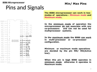
The 8086 microprocessor can work in two
modes of operations : Minimum mode and
Maximum mode.
In the minimum mode of operation the
microprocessor do not associate with any
co-processors and can not be used for
multiprocessor systems.
In the maximum mode the 8086 can work
in multi-processor or co-processor
configuration.
Minimum or maximum mode operations
are decided by the pin MN/ MX(Active
low).
When this pin is high 8086 operates in
minimum mode otherwise it operates in
Maximum mode.
3.
3
Pins and Signals
8086Microprocessor
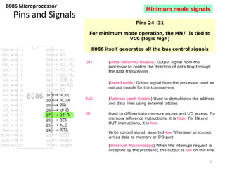
Pins 24 -31
For minimum mode operation, the MN/ is tied to
VCC (logic high)
8086 itself generates all the bus control signals
DT/ (Data Transmit/ Receive) Output signal from the
processor to control the direction of data flow through
the data transceivers
(Data Enable) Output signal from the processor used as
out put enable for the transceivers
ALE (Address Latch Enable) Used to demultiplex the address
and data lines using external latches
M/ Used to differentiate memory access and I/O access. For
memory reference instructions, it is high. For IN and
OUT instructions, it is low.
Write control signal; asserted low Whenever processor
writes data to memory or I/O port
(Interrupt Acknowledge) When the interrupt request is
accepted by the processor, the output is low on this line.
Minimum mode signals
4.
4
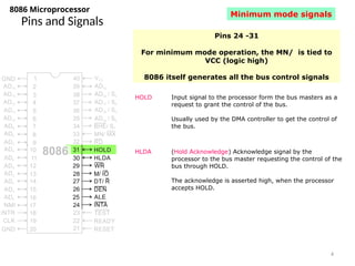
Pins and Signals
8086Microprocessor
HOLD Input signal to the processor form the bus masters as a
request to grant the control of the bus.
Usually used by the DMA controller to get the control of
the bus.
HLDA (Hold Acknowledge) Acknowledge signal by the
processor to the bus master requesting the control of the
bus through HOLD.
The acknowledge is asserted high, when the processor
accepts HOLD.
Minimum mode signals
Pins 24 -31
For minimum mode operation, the MN/ is tied to
VCC (logic high)
8086 itself generates all the bus control signals
5.
5
Pins and Signals
8086Microprocessor
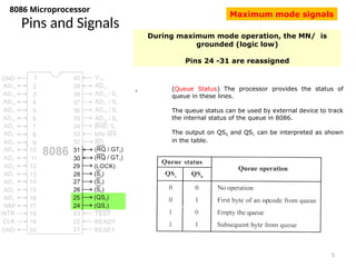
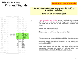
During maximum mode operation, the MN/ is
grounded (logic low)
Pins 24 -31 are reassigned
, (Queue Status) The processor provides the status of
queue in these lines.
The queue status can be used by external device to track
the internal status of the queue in 8086.
The output on QS0 and QS1 can be interpreted as shown
in the table.
Maximum mode signals
6.
6
Pins and Signals
8086Microprocessor
During maximum mode operation, the MN/ is
grounded (logic low)
Pins 24 -31 are reassigned
, (Bus Request/ Bus Grant) These requests are used by
other local bus masters to force the processor to release
the local bus at the end of the processor’s current bus
cycle.
These pins are bidirectional.
The request on will have higher priority than
An output signal activated by the LOCK prefix instruction.
Remains active until the completion of the instruction
prefixed by LOCK.
The 8086 output low on the pin while executing an
instruction prefixed by LOCK to prevent other bus
masters from gaining control of the system bus.
Maximum mode signals