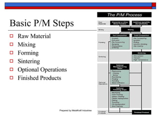
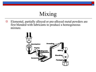
Powdered Metallurgy :  The Basics
Basics of P/M Highly developed method of manufacturing precision metal parts Made by mixing elemental or alloy powders then compacting the mixture in a die.  The resulting shape is sintered in an atmosphere controlled furnace to convert mechanical bonds into metallurgical bonds. Basically a ”chip-less” process, P/M uses roughly 97% of the starting material in the finished part.
Advantages of P/M Versatile in numerous industries Eliminates or minimizes machining Minimizes scrap Maintains close dimensional tolerances Permits a wide variety of alloy systems Facilitates manufacture of complex shapes which would be impractical with other processes Provides excellent part to part repeatability Cost Effective Energy and environmentally efficient
Basic P/M Steps Raw Material Mixing Forming Sintering Optional Operations Finished Products
Mixing Elemental, partially alloyed or pre-alloyed metal powders are first blended with lubricants to produce a homogeneous mixture.
Compaction A controlled amount of a mixed powder is gravity fed into a precision die and then compacted.  Compaction occurs at room temperature, at a pressure range of 25-50 tons per sq. in. Compacting the loose powder produces a “green compact” which, with conventional pressing techniques,  has the size and shape of the finished part when ejected from the press. Green compacts have sufficient strength for in-process handling. Typical compaction techniques use rigid dies, set into mechanical or hydraulic presses.
Conventional Mechanical Press
Compaction Tooling
Compaction Cycle Cycle Start Charge die w/powder Compaction begins Compaction complete Ejection of compact Recharging of die


Sintering Typically, the “green compact” is placed on a mesh belt which then moves slowly through a controlled atmosphere furnace.  The parts are heated below the melting point of the base metal, held at the sintering temperature, then cooled.  Basically a solid state process, sintering transforms compacted mechanical bonds between powder particles into metallurgical bonds. Typical sintering temperatures for ferrous based metals range from 2050- 2100 degrees F. Standard cycle times range from 2-3 hours.
Conventional Furnace Profile
Optional Operations
Optional Operations
Powdered Metallurgy: Design Considerations
Material Selection
Design Considerations Dimensional accuracy depends upon: Control of powder composition Size of dimension Control of powder fed to the tools with each stroke Control of press and tooling variables Control of sintering variables
MPIF Reference Tolerance Guide Typical tolerances for ferrous P/M components up to 2.00 inches in dimension Tolerances, inch/inch ±.001 ±.0015 Parallel of Ends ±.001 ±.002 Flatness on Ends .004 .006 Concentricity ±.001 ±.002 Outside Diameter ±.001 ±.002 Inside Diameter ±.003 ±.005 Length Possible Practical Characteristic
Design Details Fillets and Radii   Tooling with such fillets are more economical, longer lasting Parts made with generous fillets are more economical Parts made with fillets have greater structural integrity
Design Details Holes in the pressing direction can be round, D-Shaped, keyways or splines Wall thickness is all important; walls thinner than .060 inches are avoided. Flatness depends on part thickness and surface area. Thin parts tend to distort more than thick parts Chamfers rather than radii are necessary on part edges
Questions:

P/M: Basics

  • 1.
  • 2.
    Basics of P/MHighly developed method of manufacturing precision metal parts Made by mixing elemental or alloy powders then compacting the mixture in a die. The resulting shape is sintered in an atmosphere controlled furnace to convert mechanical bonds into metallurgical bonds. Basically a ”chip-less” process, P/M uses roughly 97% of the starting material in the finished part.
  • 3.
    Advantages of P/MVersatile in numerous industries Eliminates or minimizes machining Minimizes scrap Maintains close dimensional tolerances Permits a wide variety of alloy systems Facilitates manufacture of complex shapes which would be impractical with other processes Provides excellent part to part repeatability Cost Effective Energy and environmentally efficient
  • 4.
    Basic P/M StepsRaw Material Mixing Forming Sintering Optional Operations Finished Products
  • 5.
    Mixing Elemental, partiallyalloyed or pre-alloyed metal powders are first blended with lubricants to produce a homogeneous mixture.
  • 6.
    Compaction A controlledamount of a mixed powder is gravity fed into a precision die and then compacted. Compaction occurs at room temperature, at a pressure range of 25-50 tons per sq. in. Compacting the loose powder produces a “green compact” which, with conventional pressing techniques, has the size and shape of the finished part when ejected from the press. Green compacts have sufficient strength for in-process handling. Typical compaction techniques use rigid dies, set into mechanical or hydraulic presses.
  • 7.
  • 8.
  • 9.
    Compaction Cycle CycleStart Charge die w/powder Compaction begins Compaction complete Ejection of compact Recharging of die
  • 10.
  • 11.
  • 12.
  • 13.
  • 14.
    Sintering Typically, the“green compact” is placed on a mesh belt which then moves slowly through a controlled atmosphere furnace. The parts are heated below the melting point of the base metal, held at the sintering temperature, then cooled. Basically a solid state process, sintering transforms compacted mechanical bonds between powder particles into metallurgical bonds. Typical sintering temperatures for ferrous based metals range from 2050- 2100 degrees F. Standard cycle times range from 2-3 hours.
  • 15.
  • 16.
  • 17.
  • 18.
  • 19.
  • 20.
    Design Considerations Dimensionalaccuracy depends upon: Control of powder composition Size of dimension Control of powder fed to the tools with each stroke Control of press and tooling variables Control of sintering variables
  • 21.
    MPIF Reference ToleranceGuide Typical tolerances for ferrous P/M components up to 2.00 inches in dimension Tolerances, inch/inch ±.001 ±.0015 Parallel of Ends ±.001 ±.002 Flatness on Ends .004 .006 Concentricity ±.001 ±.002 Outside Diameter ±.001 ±.002 Inside Diameter ±.003 ±.005 Length Possible Practical Characteristic
  • 22.
    Design Details Filletsand Radii Tooling with such fillets are more economical, longer lasting Parts made with generous fillets are more economical Parts made with fillets have greater structural integrity
  • 23.
    Design Details Holesin the pressing direction can be round, D-Shaped, keyways or splines Wall thickness is all important; walls thinner than .060 inches are avoided. Flatness depends on part thickness and surface area. Thin parts tend to distort more than thick parts Chamfers rather than radii are necessary on part edges
  • 24.