Download to read offline
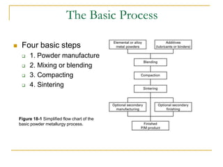
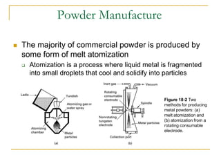
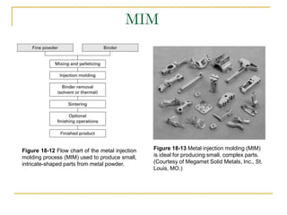
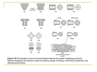
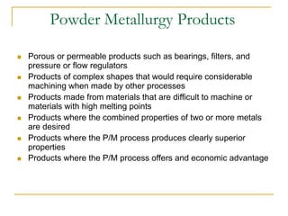
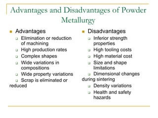
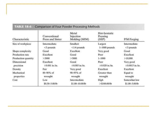

Powder metallurgy involves blending metal powders, pressing them into shapes, and sintering the parts to bond them. It allows for intricate small parts with complex compositions to be produced with little waste. The process involves powder production, mixing, compacting, and sintering. Proper powder characteristics and processing parameters are important to achieve the desired properties in the final parts.


