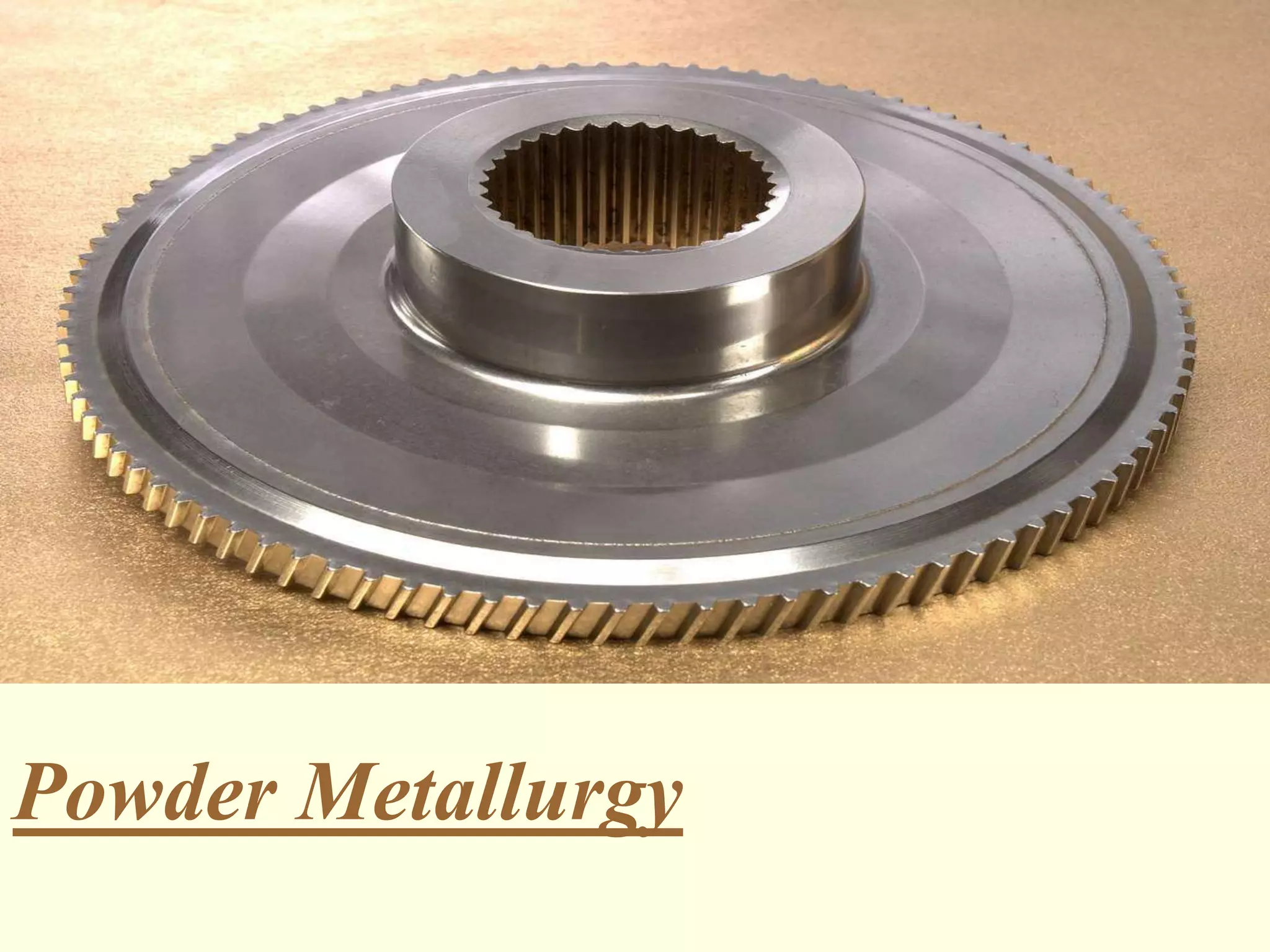
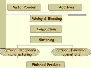
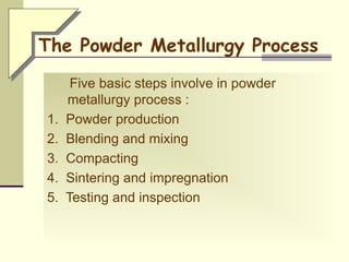
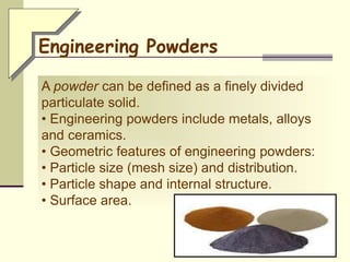
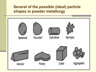
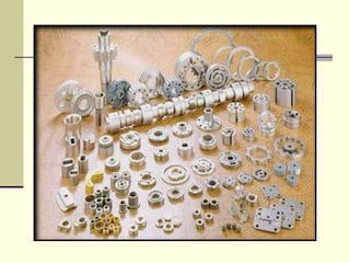
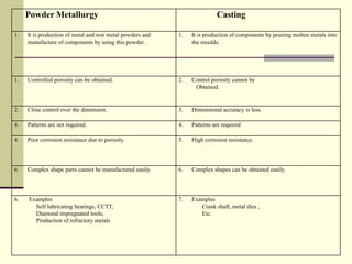
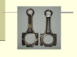
Powder Metallurgy
INDEX
1. Introduction
2. Powder Metallurgy Process :
a. Powder Manufacture.
b. Blending ,Mixing.
c. Compaction.
d. Sintering.
e. Secondary Operations.
f. Impregnation and Infiltration .
3. Advantages ,Disadvantages , conclusions,
Applications.
4. Manufacture of some important P/M components
• 3000 B.C. Egyptians made tools with powder
metallurgy
• 1900’s tungsten filament for light bulb
• 1930’s carbide tool materials
• 1960’s automobile parts
• 1980’s aircraft engine turbine parts
• Currently, North American P/M sales are over
$5billion annually
History of Applications
The Delhi Iron Pillar was
produced in the fourth century
AD by a technique that would
appear to be very similar to
current powder forging, in
which sponge iron pieces
obtained by direct reduction of
selected iron ore pieces were
hot forged successively into a
long cylindrical object.
Indian History
• PM parts can be mass produced to net
shape or near net shape, eliminating or
reducing the need for subsequent machining.
• PM parts can be made with a specified level
of porosity, to produce porous metal parts.
• Examples: filters, oil-impregnated bearings
and gears.
• Certain metals that are difficult to fabricate by
other methods can be shaped by powder
metallurgy.
Why Powder Metallurgy is Important?
• Example: Tungsten filaments for incandescent
lamp bulbs.
• PM compares favorably to most casting
processes in dimensional control.
• The Characterization of Engineering Powders.
• Production of Metallic Powders.
• Conventional Pressing and Sintering.
• Alternative Pressing and Sintering Techniques.
• Design Considerations in Powder Metallurgy.
Basics of Powder Metallurgy
Metal Powder
Mixing & Blending
Compaction
Sintering
optional Finishing
operations
optional secondary
manufacturing
Finished Product
Additives
The Powder Metallurgy Process
Five basic steps involve in powder
metallurgy process :
1. Powder production
2. Blending and mixing
3. Compacting
4. Sintering and impregnation
5. Testing and inspection
A powder can be defined as a finely divided
particulate solid.
• Engineering powders include metals, alloys
and ceramics.
• Geometric features of engineering powders:
• Particle size (mesh size) and distribution.
• Particle shape and internal structure.
• Surface area.
Engineering Powders
Characterization
Chemical
Composition
Shape, Size &
distribution
Particle porosity
& microstructure
Other
properties
Sedimentation
method
Microscopic
method
Sieve
method
Cold
mounting
Hot
mounting
Flow rate
Density
Specific
surface
Compacting
properties
Several of the possible (ideal) particle
shapes in powder metallurgy
Production of Metallic Powders
Powder Production Processes
Physical
Machining
Mechanical
Graining
Atomization
Chemical Electrochemical
Shotting
Milling
Crushing
Condensation
Thermal
Decomposition
Precipitation
Intergranular
Corrosion
Reduction
Machining: relatively coarse powders are
obtained by this method
Crushing: this method is very suitable for brittle
materials
Milling: can be obtained powders of required
grade and fineness
Mechanical Processes
Ball Mill Mechanical
Several atomization methods
a and b – gas Atomization c – water atomization d - centrifugal atomization
Atomization
Water Atomization Process:
Source "Powder Metallurgy Science" Second Edition, R.M. German, MPIF.
Vertical Gas Atomizer:
Source "Powder Metallurgy Science" Second Edition, R.M. German, MPIF.
Centrifugal Atomization by the Rotating Electrode
Process:
Source "Powder Metallurgy Science" Second Edition, R.M. German, MPIF.
Chemical methods constitute the final
manufacturing group. Included are the
production of metal powders by the reduction of
metallic oxides, precipitation from solution
(hydrometallurgy), and thermal decomposition
(carbonyl)
Chemical Processes
Electrolytic Cell Operation for Deposition of Powder-
Schematic:
Source "Powder Metallurgy Science" Second Edition, R.M. German, MPIF.
Electrolytic
Condensation: metal vapours are condensed
and suitable for volatile metals
Thermal Decomposition: highly suitable for
manufacture of Fe and Ni powders
Physical Processes
Range of particle sizes
• For successful results in compaction and
sintering, the starting powders must be
homogenized.
• Blending - powders of the same chemistry but
possibly different particle sizes are intermingled.
• Different particle sizes are often blended to
reduce porosity.
Blending of Powders
• Mixing - powders of different chemistries are
combined.
• PM technology allows mixing various metals
into alloys that would be difficult or impossible to
produce by other means.
• Other ingredients.
• Lubricants – reduce friction between particles
and die walls , Lubricant affects both sintered
and un-sintered strengths.
• Binders – achieve adequate strength for un-
sintered part.
• De-flocculants – avoid aggolomeration.
Mixing of Powders
•The purpose of mixing is to provide a
homogeneous mixture and to incorporate the
lubricant.
.
• Application of high pressure to the powders to
form them into the required shape.
• The conventional compaction method is
pressing, in which opposing punches squeeze
the powders contained in a die.
• The work part after pressing is called a green
compact, the word green meaning not yet fully
processed.
Compacting
Pressing in PM: (1) filling die cavity with powder
by automatic feeder; (2) initial and (3) final
positions of upper and lower punches during
pressing, and(4) ejection of part
Effect of compaction pressure on green density
Consolidation of powdered material can also be
done by:
• Isostatic pressing
• High energy rate forming
• Powder rolling or Roll compacting
• Powder extrusion
• Vibratory compacting
• Here pressure is applied simultaneously and
equally in all direction through gases or
hydraulic medium to obtain uniform density
and strength.
• Produces powder metal parts to near full
density and shapes of varying complexity.
• Uses lower pressures to densify a powder
by atomic movement.
Isostatic Pressing
Hot Isostatic Pressure System
Importance
• It reduces voids , increases the density.
• It produces adhesion It plastically deforms the
powder and allows recrystallization during
sintering.
• Final Shape and Mechanical properties are
determined.
• Die Compacting
• Cold-welding of particles
Forming
Pre-sintering
• Quite complex depends on process
parameters.
• Sintering time, pressure and atmosphere.
• Mechanism involved are
a.Diffusion
b.Densification
c. Recrystallization
d.Grain growth
• Sinter involves mass transport (diffusion) to
create necks and transform into grain
boundaries. Powder size small, higher surface
area and greater driving force.
Mechanism in sintering
• Main operation.
• Heating material below melting point to bond
particles and increase strength.
• Uses a sintering atmosphere and a sintering
furnace ( Continuous Belt Furnace).
• The atmosphere transfers heat to the
compacted powder, adjusts impurity levels and
remove lubricants.
• Atmosphere can be pure hydrogen, nitrogen
or ammonia.
Sintering Process
Continuous Belt Furnace Bonding of particles in Sintering
• The particles will stretch and densification
will form in places of rapid shrinking.
Sintering on Particles
• Furnace provides time and temp. control.
Continuous Furnace
Typical sintering cycle
• Heat treatment to bond the metallic particles,
thereby increasing strength and hardness.
• Usually carried out at between 70% and 90%
of the metal's melting point (absolute scale).
• Primary driving force for sintering is reduction
of surface energy.
• Part shrinkage occurs during sintering due to
pore size reduction.
Sintering–solid state/phase sinterin
Sintering on a microscopic scale: (1) particle bonding is initiated at
contact points; (2) contact points grow into "necks"; (3) the pores
between particles are reduced in size; and (4) grain boundaries
develop between particles in place of the necked regions
Sintering – time and temperature
on density and strength
• Increase in density and strength.
• Disappearance of particle boundaries.
• Other mechanism is plastic deformation.
• Liquid phase sintering (alloys).
Importance
• Voids
• Incomplete fusion
Sintering Problems
Secondary operations are performed to increase
density, improve accuracy, or accomplish
additional shaping of the sintered part
• Repressing - pressing the sintered part in a
closed die to increase density and improve
properties.
• Sizing - pressing a sintered part to improve
dimensional accuracy.
• Coining – press working operation on a
sintered part to press details into its surface.
Secondary Operations
Machining - creates geometric features that
cannot be achieved by pressing, such as
threads, side holes, and other details
• Compaction and sintering together
• Hot Isostatic pressing
• Spark sintering
• Porosity is a unique and inherent characteristic
of PM technology.
• It can be exploited to create special products
by filling the available pore space with oils,
polymers, or metals.
Impregnation and Infiltration
Two categories:
1. Impregnation
The term used when oil or other fluid is
permeated into the pores of a sintered PM part.
2. Infiltration
An operation in which the pores of the PM part
are filled with a molten metal.
• Ceramic particles are mixed with a thermoplastic
polymer/metal, then heated and injected into a mold
cavity.
• The polymer acts as a carrier and provides flow
characteristics for molding.
• Upon cooling which hardens the polymer, the mold is
opened and the part is removed.
• Because temperatures needed to plasticize the carrier
are much lower than those required for sintering the
ceramic, the piece is green after molding.
• The plastic binder is removed and the remaining
ceramic part is sintered.
Powder/Metal Injection Molding (PIM/MIM)
1.Ability to create complex shapes
2.High strength properties
3.Low material waste
4.Good microstructure control
5.Uses more than 97% of the starting raw
material in the finished part
6.Eliminates or minimizes machining
7.Maintains close dimensional tolerances
8.Wide variety of alloys
9.Mass production
10.Cost and energy efficient
Advantages
1. Cost of powder production.
2. Limit on complexity of shapes.
3. Size will change during sintering.
4. can be predicted.
5. Potential workforce health problems due to
atmospheric contamination.
6. Creation of residual pores.
7. High tooling costs.
Disadvantages
8. Variations in density throughout part may be
a problem,especially for complex geometries.
• P/M is a proven technology dating back
centuries.
• By utilizing 97% original material, cost and
energy are minimized
• Properties and dimensions are easily
controlled.
• Wide variety of P/M applications which are still
increasing
Conclusions
• Only way of forming superalloys, tungsten
carbide.
• Typical U.S. 5- or 6-passenger car contains
more than 35 lbs of P/M parts.
• Commercial aircraft engines contain
1,500-4,400 lbs of P/M parts.
• Gears, cams.
• Household goods.
Applications
other
industrial-machinery
oil-pump
gear-parts
pulley-parts
self-lubrication-bearing
automobile-motorcycle
Powdered Metal Turbine blade-disk
Manufacture of some important P/M
components
• Self lubricating bearings
• Cemented carbide tipped tools
• Diamond impregnated tools
• Production of refractory metals
• Electrical contact materials
Self lubricating Bearings
• Manufactured from either bronze , brass ,
iron or aluminium alloy powders with or
without graphite.
• Bronze bearings are widely used (Cu:Sn-
90:10).
• Some amount of free graphite is desirable
because it is a solid lubricant and takes care
under severe loading conditions.
The steps in the production of a
porous bronze bearing
1.Mixing
2.Cold compaction
3.Sintering
• Reducing atmosphere
• 400-450 C for 1-2 hours to remove part of
graphite
• 800 C for 5 minutes for diffusion of molten
Sn into Cu
4. Repressing or Machining
• Pore size - large – sizing
- small - machining
5. Impregnation
Characteristics
• Sufficient porosity
• Inter connected porosity
• Sufficient strength
• Good dimensional accuracy
• Effect of porosity
Applications
• Difficultly accessible places
• Regular lubrication
• Applications where it is desirable that oil
should not come in contact and contaminate
the product
SLB with slightly porous appearance
Oil-impregnated Porous Bronze
Bearings
Cemented Carbides
• Important products of P/M.
• Find wide applications as cutting tools, wire
drawing and deep drawing dries .
• Manufactured from carbides of refractory
metals such as W, Mo ,Ti ,Ta or Nb.
• Extremely hard and retain their hardness upto
a very high temperature.
• However they are extremely brittle and are
likely to fail with slight shock loading.
The Steps In Manufacture Of
Cemented Carbides:
• Powder manufacture
• Milling
To facilitate pressing
Avoid defects and cracks
• Cold pressing and sintering
400 C removal of lubricant
900-1150 C sufficient strength
1350-1550 C hydrogen atmosphere
• Machining
Tungsten
Carbon
Carbide solid solution
Crushed & screened
screened
Re-reduced
Ball mill
Dried
Final sintering
W & C powder
Carburized
pressing
Presintring
Lubricant add
CCTT
Pressing
Characteristics
• Cold and hot hardness
• Compressive strength
• Modulus of elasticity
• Abrasion resistance
• Cutting ability
Production of refractory metals
• Refractory metals
• W, Mo, Nb, Ta, Pt
• Powder production
• Cold compaction
• Presintering
• Final sintering
• by passing electric current
• Applications
• high temp furnace, hook in thermoionic
valve,
Diamond Impregnated Tools
Composition
• Diamond dust
• Powder of bonding material
Production process
• Cold compaction
• Sintering
• 1000 C in vacuum or reducing atmosphere
Characteristics
• Close dimensional tolerances
• Cutting efficiency
• Surface finish
• Long tool life
Applications
• Cutting, Drilling, Shaping, Sawing, Finishing
• For wire drawing
Electrical contact materials
Properties required
• High electrical and thermal conductivity
• High melting point
• High resistance to wear, abrasion and
sparking
• Low contact resistance
• Low vapour pressure
Manufacturing processes
• Conventional pressing and sintering
followed by further cold or hot working
• Pressing, sintering and infiltration
Examples
Simple refractory metals such as W and Mo,
W-Cu, W-Ag, WC-Ag, Ni-Ag, Ag-graphite,
Cu-graphite
Powder Metallurgy Casting
1. It is production of metal and non metal powders and
manufacture of components by using this powder.
1. It is production of components by pouring molten metals into
the moulds.
1. Controlled porosity can be obtained. 2. Control porosity cannot be
Obtained.
2. Close control over the dimension. 3. Dimensional accuracy is less.
4. Patterns are not required. 4. Patterns are required
4. Poor corrosion resistance due to porosity. 5. High corrosion resistance.
6. Complex shape parts cannot be manufactured easily. 6. Complex shapes can be obtained easily.
6. Examples
Self lubricating bearings, CCTT,
Diamond impregnated tools,
Production of refractory metals
7. Examples
Crank shaft, metal dies ,
Etc.
Cermet cutting inserts for lathe
Thank you !

365538336-Powder-Metallurgy-Ppt.ppt

  • 1.
  • 2.
    INDEX 1. Introduction 2. PowderMetallurgy Process : a. Powder Manufacture. b. Blending ,Mixing. c. Compaction. d. Sintering. e. Secondary Operations. f. Impregnation and Infiltration . 3. Advantages ,Disadvantages , conclusions, Applications. 4. Manufacture of some important P/M components
  • 3.
    • 3000 B.C.Egyptians made tools with powder metallurgy • 1900’s tungsten filament for light bulb • 1930’s carbide tool materials • 1960’s automobile parts • 1980’s aircraft engine turbine parts • Currently, North American P/M sales are over $5billion annually History of Applications
  • 4.
    The Delhi IronPillar was produced in the fourth century AD by a technique that would appear to be very similar to current powder forging, in which sponge iron pieces obtained by direct reduction of selected iron ore pieces were hot forged successively into a long cylindrical object. Indian History
  • 5.
    • PM partscan be mass produced to net shape or near net shape, eliminating or reducing the need for subsequent machining. • PM parts can be made with a specified level of porosity, to produce porous metal parts. • Examples: filters, oil-impregnated bearings and gears. • Certain metals that are difficult to fabricate by other methods can be shaped by powder metallurgy. Why Powder Metallurgy is Important?
  • 6.
    • Example: Tungstenfilaments for incandescent lamp bulbs. • PM compares favorably to most casting processes in dimensional control.
  • 7.
    • The Characterizationof Engineering Powders. • Production of Metallic Powders. • Conventional Pressing and Sintering. • Alternative Pressing and Sintering Techniques. • Design Considerations in Powder Metallurgy. Basics of Powder Metallurgy
  • 8.
    Metal Powder Mixing &Blending Compaction Sintering optional Finishing operations optional secondary manufacturing Finished Product Additives
  • 9.
    The Powder MetallurgyProcess Five basic steps involve in powder metallurgy process : 1. Powder production 2. Blending and mixing 3. Compacting 4. Sintering and impregnation 5. Testing and inspection
  • 10.
    A powder canbe defined as a finely divided particulate solid. • Engineering powders include metals, alloys and ceramics. • Geometric features of engineering powders: • Particle size (mesh size) and distribution. • Particle shape and internal structure. • Surface area. Engineering Powders
  • 11.
    Characterization Chemical Composition Shape, Size & distribution Particleporosity & microstructure Other properties Sedimentation method Microscopic method Sieve method Cold mounting Hot mounting Flow rate Density Specific surface Compacting properties
  • 12.
    Several of thepossible (ideal) particle shapes in powder metallurgy
  • 13.
  • 14.
    Powder Production Processes Physical Machining Mechanical Graining Atomization ChemicalElectrochemical Shotting Milling Crushing Condensation Thermal Decomposition Precipitation Intergranular Corrosion Reduction
  • 15.
    Machining: relatively coarsepowders are obtained by this method Crushing: this method is very suitable for brittle materials Milling: can be obtained powders of required grade and fineness Mechanical Processes
  • 16.
  • 17.
    Several atomization methods aand b – gas Atomization c – water atomization d - centrifugal atomization
  • 18.
    Atomization Water Atomization Process: Source"Powder Metallurgy Science" Second Edition, R.M. German, MPIF.
  • 19.
    Vertical Gas Atomizer: Source"Powder Metallurgy Science" Second Edition, R.M. German, MPIF.
  • 20.
    Centrifugal Atomization bythe Rotating Electrode Process: Source "Powder Metallurgy Science" Second Edition, R.M. German, MPIF.
  • 21.
    Chemical methods constitutethe final manufacturing group. Included are the production of metal powders by the reduction of metallic oxides, precipitation from solution (hydrometallurgy), and thermal decomposition (carbonyl) Chemical Processes
  • 22.
    Electrolytic Cell Operationfor Deposition of Powder- Schematic: Source "Powder Metallurgy Science" Second Edition, R.M. German, MPIF. Electrolytic
  • 23.
    Condensation: metal vapoursare condensed and suitable for volatile metals Thermal Decomposition: highly suitable for manufacture of Fe and Ni powders Physical Processes
  • 24.
  • 25.
    • For successfulresults in compaction and sintering, the starting powders must be homogenized. • Blending - powders of the same chemistry but possibly different particle sizes are intermingled. • Different particle sizes are often blended to reduce porosity. Blending of Powders
  • 26.
    • Mixing -powders of different chemistries are combined. • PM technology allows mixing various metals into alloys that would be difficult or impossible to produce by other means. • Other ingredients. • Lubricants – reduce friction between particles and die walls , Lubricant affects both sintered and un-sintered strengths. • Binders – achieve adequate strength for un- sintered part. • De-flocculants – avoid aggolomeration. Mixing of Powders
  • 27.
    •The purpose ofmixing is to provide a homogeneous mixture and to incorporate the lubricant. .
  • 28.
    • Application ofhigh pressure to the powders to form them into the required shape. • The conventional compaction method is pressing, in which opposing punches squeeze the powders contained in a die. • The work part after pressing is called a green compact, the word green meaning not yet fully processed. Compacting
  • 29.
    Pressing in PM:(1) filling die cavity with powder by automatic feeder; (2) initial and (3) final positions of upper and lower punches during pressing, and(4) ejection of part
  • 30.
    Effect of compactionpressure on green density
  • 31.
    Consolidation of powderedmaterial can also be done by: • Isostatic pressing • High energy rate forming • Powder rolling or Roll compacting • Powder extrusion • Vibratory compacting
  • 32.
    • Here pressureis applied simultaneously and equally in all direction through gases or hydraulic medium to obtain uniform density and strength. • Produces powder metal parts to near full density and shapes of varying complexity. • Uses lower pressures to densify a powder by atomic movement. Isostatic Pressing
  • 33.
  • 34.
    Importance • It reducesvoids , increases the density. • It produces adhesion It plastically deforms the powder and allows recrystallization during sintering.
  • 35.
    • Final Shapeand Mechanical properties are determined. • Die Compacting • Cold-welding of particles Forming Pre-sintering
  • 36.
    • Quite complexdepends on process parameters. • Sintering time, pressure and atmosphere. • Mechanism involved are a.Diffusion b.Densification c. Recrystallization d.Grain growth • Sinter involves mass transport (diffusion) to create necks and transform into grain boundaries. Powder size small, higher surface area and greater driving force. Mechanism in sintering
  • 37.
    • Main operation. •Heating material below melting point to bond particles and increase strength. • Uses a sintering atmosphere and a sintering furnace ( Continuous Belt Furnace). • The atmosphere transfers heat to the compacted powder, adjusts impurity levels and remove lubricants. • Atmosphere can be pure hydrogen, nitrogen or ammonia. Sintering Process
  • 38.
    Continuous Belt FurnaceBonding of particles in Sintering
  • 39.
    • The particleswill stretch and densification will form in places of rapid shrinking. Sintering on Particles
  • 40.
    • Furnace providestime and temp. control. Continuous Furnace
  • 41.
  • 42.
    • Heat treatmentto bond the metallic particles, thereby increasing strength and hardness. • Usually carried out at between 70% and 90% of the metal's melting point (absolute scale). • Primary driving force for sintering is reduction of surface energy. • Part shrinkage occurs during sintering due to pore size reduction. Sintering–solid state/phase sinterin
  • 43.
    Sintering on amicroscopic scale: (1) particle bonding is initiated at contact points; (2) contact points grow into "necks"; (3) the pores between particles are reduced in size; and (4) grain boundaries develop between particles in place of the necked regions
  • 44.
    Sintering – timeand temperature on density and strength
  • 45.
    • Increase indensity and strength. • Disappearance of particle boundaries. • Other mechanism is plastic deformation. • Liquid phase sintering (alloys). Importance
  • 46.
    • Voids • Incompletefusion Sintering Problems
  • 47.
    Secondary operations areperformed to increase density, improve accuracy, or accomplish additional shaping of the sintered part • Repressing - pressing the sintered part in a closed die to increase density and improve properties. • Sizing - pressing a sintered part to improve dimensional accuracy. • Coining – press working operation on a sintered part to press details into its surface. Secondary Operations
  • 48.
    Machining - createsgeometric features that cannot be achieved by pressing, such as threads, side holes, and other details • Compaction and sintering together • Hot Isostatic pressing • Spark sintering
  • 49.
    • Porosity isa unique and inherent characteristic of PM technology. • It can be exploited to create special products by filling the available pore space with oils, polymers, or metals. Impregnation and Infiltration
  • 50.
    Two categories: 1. Impregnation Theterm used when oil or other fluid is permeated into the pores of a sintered PM part. 2. Infiltration An operation in which the pores of the PM part are filled with a molten metal.
  • 51.
    • Ceramic particlesare mixed with a thermoplastic polymer/metal, then heated and injected into a mold cavity. • The polymer acts as a carrier and provides flow characteristics for molding. • Upon cooling which hardens the polymer, the mold is opened and the part is removed. • Because temperatures needed to plasticize the carrier are much lower than those required for sintering the ceramic, the piece is green after molding. • The plastic binder is removed and the remaining ceramic part is sintered. Powder/Metal Injection Molding (PIM/MIM)
  • 52.
    1.Ability to createcomplex shapes 2.High strength properties 3.Low material waste 4.Good microstructure control 5.Uses more than 97% of the starting raw material in the finished part 6.Eliminates or minimizes machining 7.Maintains close dimensional tolerances 8.Wide variety of alloys 9.Mass production 10.Cost and energy efficient Advantages
  • 53.
    1. Cost ofpowder production. 2. Limit on complexity of shapes. 3. Size will change during sintering. 4. can be predicted. 5. Potential workforce health problems due to atmospheric contamination. 6. Creation of residual pores. 7. High tooling costs. Disadvantages 8. Variations in density throughout part may be a problem,especially for complex geometries.
  • 54.
    • P/M isa proven technology dating back centuries. • By utilizing 97% original material, cost and energy are minimized • Properties and dimensions are easily controlled. • Wide variety of P/M applications which are still increasing Conclusions
  • 55.
    • Only wayof forming superalloys, tungsten carbide. • Typical U.S. 5- or 6-passenger car contains more than 35 lbs of P/M parts. • Commercial aircraft engines contain 1,500-4,400 lbs of P/M parts. • Gears, cams. • Household goods. Applications
  • 56.
  • 57.
  • 58.
    Manufacture of someimportant P/M components • Self lubricating bearings • Cemented carbide tipped tools • Diamond impregnated tools • Production of refractory metals • Electrical contact materials
  • 59.
    Self lubricating Bearings •Manufactured from either bronze , brass , iron or aluminium alloy powders with or without graphite. • Bronze bearings are widely used (Cu:Sn- 90:10). • Some amount of free graphite is desirable because it is a solid lubricant and takes care under severe loading conditions.
  • 60.
    The steps inthe production of a porous bronze bearing 1.Mixing 2.Cold compaction 3.Sintering • Reducing atmosphere • 400-450 C for 1-2 hours to remove part of graphite • 800 C for 5 minutes for diffusion of molten Sn into Cu
  • 61.
    4. Repressing orMachining • Pore size - large – sizing - small - machining 5. Impregnation
  • 62.
    Characteristics • Sufficient porosity •Inter connected porosity • Sufficient strength • Good dimensional accuracy • Effect of porosity
  • 63.
    Applications • Difficultly accessibleplaces • Regular lubrication • Applications where it is desirable that oil should not come in contact and contaminate the product
  • 64.
    SLB with slightlyporous appearance
  • 65.
  • 66.
    Cemented Carbides • Importantproducts of P/M. • Find wide applications as cutting tools, wire drawing and deep drawing dries . • Manufactured from carbides of refractory metals such as W, Mo ,Ti ,Ta or Nb. • Extremely hard and retain their hardness upto a very high temperature. • However they are extremely brittle and are likely to fail with slight shock loading.
  • 67.
    The Steps InManufacture Of Cemented Carbides: • Powder manufacture • Milling To facilitate pressing Avoid defects and cracks • Cold pressing and sintering 400 C removal of lubricant 900-1150 C sufficient strength 1350-1550 C hydrogen atmosphere • Machining
  • 68.
    Tungsten Carbon Carbide solid solution Crushed& screened screened Re-reduced Ball mill Dried Final sintering W & C powder Carburized pressing Presintring Lubricant add CCTT Pressing
  • 69.
    Characteristics • Cold andhot hardness • Compressive strength • Modulus of elasticity • Abrasion resistance • Cutting ability
  • 70.
    Production of refractorymetals • Refractory metals • W, Mo, Nb, Ta, Pt • Powder production • Cold compaction • Presintering • Final sintering • by passing electric current • Applications • high temp furnace, hook in thermoionic valve,
  • 71.
    Diamond Impregnated Tools Composition •Diamond dust • Powder of bonding material Production process • Cold compaction • Sintering • 1000 C in vacuum or reducing atmosphere
  • 72.
    Characteristics • Close dimensionaltolerances • Cutting efficiency • Surface finish • Long tool life Applications • Cutting, Drilling, Shaping, Sawing, Finishing • For wire drawing
  • 73.
    Electrical contact materials Propertiesrequired • High electrical and thermal conductivity • High melting point • High resistance to wear, abrasion and sparking • Low contact resistance • Low vapour pressure
  • 74.
    Manufacturing processes • Conventionalpressing and sintering followed by further cold or hot working • Pressing, sintering and infiltration Examples Simple refractory metals such as W and Mo, W-Cu, W-Ag, WC-Ag, Ni-Ag, Ag-graphite, Cu-graphite
  • 76.
    Powder Metallurgy Casting 1.It is production of metal and non metal powders and manufacture of components by using this powder. 1. It is production of components by pouring molten metals into the moulds. 1. Controlled porosity can be obtained. 2. Control porosity cannot be Obtained. 2. Close control over the dimension. 3. Dimensional accuracy is less. 4. Patterns are not required. 4. Patterns are required 4. Poor corrosion resistance due to porosity. 5. High corrosion resistance. 6. Complex shape parts cannot be manufactured easily. 6. Complex shapes can be obtained easily. 6. Examples Self lubricating bearings, CCTT, Diamond impregnated tools, Production of refractory metals 7. Examples Crank shaft, metal dies , Etc.
  • 78.
  • 79.