Downloaded 101 times
![Using the charts
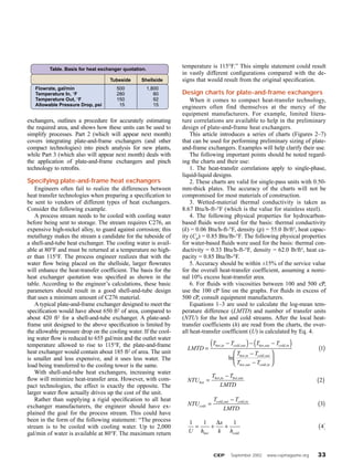
Consider the following example.
150,000 lb/h of water is being cooled
from 200°F to 175°F by 75,000 lb/h
of SAE 30 oil. The oil enters the ex-
changer at 60°F and leaves at 168°F.
The average viscosity of the water
passing through the unit is 0.33 cP
and the average viscosity of the oil in
the unit is 215 cP. The maximum-
allowable pressure drop through the
plate heat exchanger is 15 psi on the
hot and cold sides.
Step 1: Calculate the LMTD.
From Eq. 1, LMTD = [(200 – 168)
– (175 – 60)]/ln[(200 – 168)/(175 –
60)] = 64.9°F.
Step 2: Calculate NTUhot and
NTUcold. From Eqs. 2 and 3, NTUhot =
(200 – 175)/64.9 = 0.38 and NTUcold
= (168 – 60)/64.9 = 1.66.
Step 3: Read hhot from the appro-
priate chart. Use Figure 5, the chart
for hydrocarbons when 0.25 < NTU
< 2.0. Although there is not a vis-
cosity line for 215 cP, the line repre-
senting 100 cP can be used for vis-
cosities up to about 400–500 cP. The
heat exchanger will be pressure-
drop-limited and the heat-transfer
coefficient will not change apprecia-
bly over this viscosity range for
plate-and-frame exchangers. Read-
ing from the chart, a pressure drop
of 15 psi corresponds to hhot ≈ 50
Btu/h-ft2-°F.
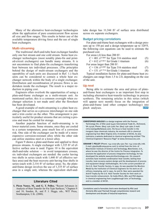
Step 4: Read hcold from the chart.
Use Figure 2, which applies to water-
based liquids when 0.25 < NTU < 2.0.
Again, the exact viscosity line needed
for pure water (0.33 cP) in this case is
not available. However, the 1.0 cP
line provides a very good estimate of
the heat-transfer coefficient for pure
water. Reading from the chart, a pres-
sure drop of 15 psi corresponds to
hcold ≈ 3,000 Btu/h-ft2-°F.
Step 5: Calculate U. Assume a
stainless steel plate with a thick-
ness of 0.50 mm is being used.
Type 316 stainless steel has a ther-
mal conductivity of 8.67 Btu/h-ft-
°F. Then from Eq. 4, 1/U = (1/50 +
0.000189 + 1/3,000) and U = 49
Btu/h-ft2-°F.
Heat Exchangers
34 www.cepmagazine.org September 2002 CEP
s Figure 2. Heat-transfer correlations for water-based fluids, 0.25 < NTU < 2.0.
Pressure Drop, psi
h=LocalHeat-TransferCoefficient,
Btu/h-ft2-˚F
h=LocalHeat-TransferCoefficient,
W/m2-K
Pressure Drop, kPa
5 10 15 20 25 30
3,500
3,000
2,500
2,000
1,500
1,000
500
0
18,000
15,000
12,000
9,000
6,000
3,000
100
1 cP
2.5 cP
5 cP
10 cP
100 cP
50 200150
Water-Based Fluids
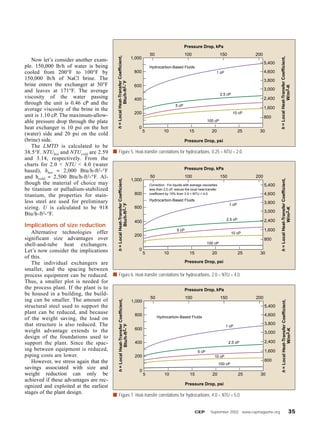
s Figure 3. Heat-transfer correlations for water-based fluids, 2.0 < NTU < 4.0.
Pressure Drop, psi
h=LocalHeat-TransferCoefficient,
Btu/h-ft2-˚F
5 10 15 20 25 30
3,500
3,000
2,500
2,000
1,500
1,000
500
0
18,000
15,000
12,000
9,000
6,000
3,000
100
1 cP
Correction: For liquids with average viscosities
less than 2.0 cP, reduce the local heat-transfer
coefficient by 15% from 3.5 < NTU < 4.0.
2.5 cP
5 cP
10 cP
100 cP
50 200150
h=LocalHeat-TransferCoefficient,
W/m2-K
Pressure Drop, kPa
Water-Based Fluids
s Figure 4. Heat-transfer correlations for water-based fluids, 4.0 < NTU < 5.0.
Pressure Drop, psi
h=LocalHeat-TransferCoefficient,
Btu/h-ft2-˚F
5 10 15 20 25 30
3,500
3,000
2,500
2,000
1,500
1,000
500
0
18,000
15,000
12,000
9,000
6,000
3,000
100
1 cP
2.5 cP
5 cP
10 cP
100 cP
50 200150
h=LocalHeat-TransferCoefficient,
W/m2-K
Pressure Drop, kPa
Water-Based Fluids](https://image.slidesharecdn.com/plateandframehxsizing-151209075309-lva1-app6892/85/Plate-and-frame-Heat-Exchanger-Sizing-3-320.jpg)
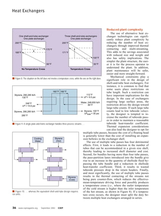

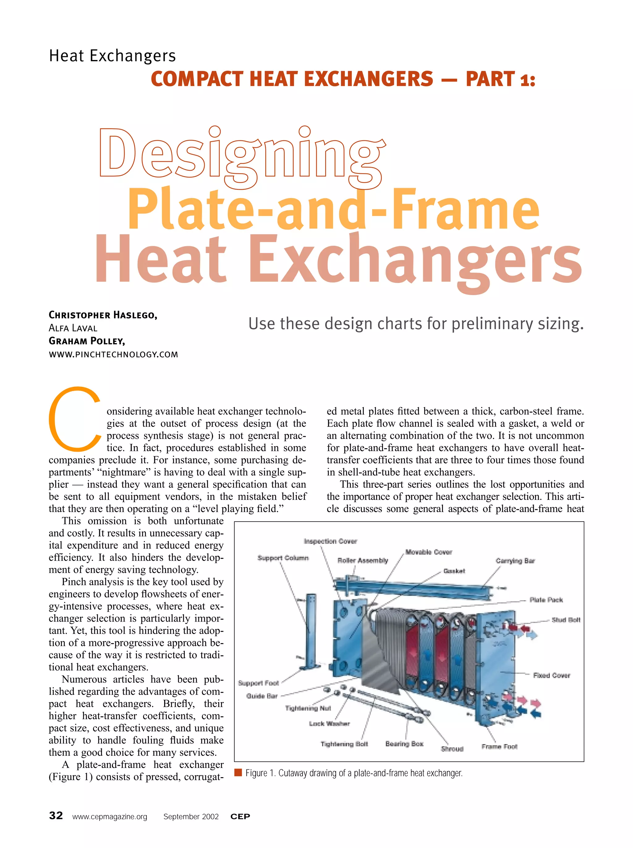
This document discusses the advantages of considering compact heat exchangers like plate-and-frame exchangers early in the process design stage. Plate-and-frame exchangers can be significantly smaller than traditional shell-and-tube exchangers while meeting the same heat transfer needs. Specifying design requirements without considering the characteristics of different exchanger types can lead to oversized and more expensive designs. Charts are provided to help estimate the required area of plate-and-frame exchangers for preliminary sizing.


