
Recommended
Recommended
More Related Content
What's hot
What's hot (20)
Similar to Heat exchanger: Shell And Tube Heat Exchanger
Similar to Heat exchanger: Shell And Tube Heat Exchanger (20)
Recently uploaded
Recently uploaded (20)
Heat exchanger: Shell And Tube Heat Exchanger
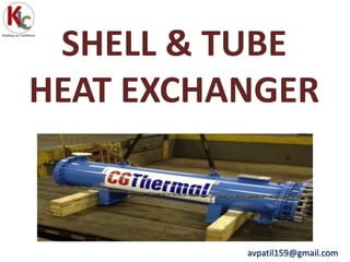
- 1. avpatil159@gmail.com SHELL & TUBE HEAT EXCHANGER
- 2. Basic Heat Exchanger Equation The general relation reflects the heat transfer across a surface is: Where, )()( cicochohih HHMHHMQ avpatil159@gmail.com Q = U A (LMTD)
- 3. Dimensionless Number • Nusselt Number • Reynolds Number • Prandtl Number avpatil159@gmail.com
- 4. Why Shell and Tube Heat Exchanger? • Relatively inexpensive • Available in many sizes • Compact design • Available in many different materials • Can be designed for high pressures without excessive cost • Design principles well known • Many different manufacturers • Well-developed fabrication facilities. avpatil159@gmail.com
- 5. Types of STHE • Fixed tube-sheet • U-tube • Floating-head avpatil159@gmail.com
- 6. Fixed Tube sheet heat exchangers avpatil159@gmail.com
- 8. Floating head heat exchanger avpatil159@gmail.com
- 9. Components of STHE • Shell • Shell cover • Tubes • Channel • Channel cover • Tube sheet • Baffles • Support plates • Floating head cover • Nozzle • Tie-rods • Spacers • Impingement plate avpatil159@gmail.com
- 10. Shell Dimensions • Line pipe dimensions shall be used for carbon steel shells up to a nominal shell diameter of 18-20 inches • For shells rolled from plate and with a shell diameter above 20 mm the nominal diameter is the shell inside diameter. • During the design stage one should follow standard HTRI shell dimensions unless detailed information is available with the designer. Orientation • Horizontal in General • Limited space or certain process requirements – Vertical Orientation • For thermo siphon re-boilers, vertical orientation is preferred to horizontal orientation, even if the heating medium is fouling. avpatil159@gmail.com
- 11. Types of SHELL avpatil159@gmail.com E-Type Shell F-Type Shell
- 12. G-Type Shell H-Type Shell avpatil159@gmail.com
- 13. J-Type Shell K-Type Shell X-Type Shell avpatil159@gmail.com
- 14. Pressure Drop of Different Shell Types F shell 8 x ΔPE shell G shell 1 x ΔPE shell H shell 1/8 x ΔPE shell J shell 1/8 x ΔPE shell X shell <1/100 x ΔPE shell avpatil159@gmail.com
- 15. Tubes • The smallest tube diameter generally produces the most heat transfer area per unit volume in a given shell and most efficient heat transfer. • 19.15 mm tubes are commonly used for clean services. • For very clean services, 15.875 mm tubes are sometimes used. • For gases, boiling, condensing or two phase flow 19.05 mm to 31.75 mm tube ODs are required. • For vertical tube side vacuum falling film evaporators tubes with outside diameter upto 2 inches are used. avpatil159@gmail.com
- 17. Tube sheets • Tubes are held on both the ends called tube sheets. • The tube sheet thickness varies from 1 inches (25 mm) for low pressure and low shell diameter applications up to over 12 in. (300 mm) in high pressure and large shell diameters. avpatil159@gmail.com
- 18. Tube to tubesheet joint • Tubes are expanded into grooves in tube sheet or welded to them. • Welded joints are preferred in sever conditions like high pressures (80 kg/cm2 g) or when handling toxic or inflammable fluids where leakage are not permitted. avpatil159@gmail.com
- 20. Tube Layout Pattern avpatil159@gmail.com Typical Tube pitch = 1.25 x tube dia.
- 21. Tube-side Passes Multiple passes are used to • Increase tube-side velocity and taking maximum advantage of available pressure drop • Reduce overall length • Allow U-tube/floating head designs avpatil159@gmail.com
- 23. Baffles • Baffles provide the framework to support and secure the tubes and prevent vibration • Baffles redirect the shell side flow across the tube bundle avpatil159@gmail.com
- 25. The construction of the bundle provides multiple fluid pathways C C B BF A -Tube-to-baffle hole leakage E - Baffle-to-shell leakage B - Main cross flow F - Pass-partition bypass C -Bundle-to-shell bypass avpatil159@gmail.com Shell Side Fluid Stream Analysis
- 26. Impingement Plate Purpose: To protect the uppermost tubes located just below the shell-side inlet nozzle against direct impingement. Such impingement can cause erosion, cavitations and/or vibration. TEMA Standards specify an impingement protection is required for following cases: • Inlet nozzle ρV2 is greater than 2232 kg/m s2 for non-corrosisve, non abrasive single pass fluid. • Shell side condensation is specified • Shell side boiling is specified and the inlet nozzle ρV2 is greater than 744kg/m s2 • for all saturated vapors and liquid-vapor mixtures (there are chances of carrying liquid droplets.) Types • Circular plate • Rectangular plate • Rods avpatil159@gmail.com
- 27. Standard Dimensions for impingement plate •Minimum height under nozzle (Hmin) = D/4, •Minimum width of the impingement plate (Wmin) = D + 50 mm, •Length of the impingement plate L = D + (50 ~ 70 mm), where D is the nozzle inside diameter. avpatil159@gmail.com
- 28. The figure below shows the height under nozzle measurement for different cases
- 29. Nozzle • Inlet and outlet nozzles are sized for pressure drop and velocity considerations. • The total nozzle pressure drop for either shell side or tube side should not exceed about 25% of total. • Nozzle pressure drop is dominating in case of condensers (due to pressure recovery in condensers). • For liquid flow nozzle rhoV2 should be limited to 3000 kg/m s2. • For gas flow, nozzle velocity should be less than 20% of acoustic velocity. • Thermo wells, pressure indicator connections, safety and relief valves, product drains, vents, block valve are other miscellaneous nozzles. avpatil159@gmail.com
- 30. Nozzle Locations • Nozzle orientation should be decided in consideration of process requirements, mechanical construction and requirements from plot plan. • Following samples can be used as a good reference. avpatil159@gmail.com
- 34. Temperature Pressure Viscosity Fouling and cleaning Corrosion Flow rate Temperature range avpatil159@gmail.com Allocation of Fluids - Parameters
- 36. Codes & Standards: TEMA R/C/B The mechanical design, fabrication, inspection and testing of shell and tube type heat exchangers shall be applied in accordance with the following sections of “TEMA” standard • TEMA Class R: Sever requirements for petroleum and related processing applications • TEMA Class C: Moderate requirements for commercial and general process applications • TEMA Class B: For chemical process service avpatil159@gmail.com