This document discusses the thermal and hydraulic design of brazed aluminum plate-fin heat exchangers. It covers topics such as single and multiple banking configurations, multi-stream designs, thermal design procedures and relationships, hydraulic design considerations, and the selection of fin geometry. Key points include defining the components of heat transfer surface area and pressure drop, methods for calculating overall heat transfer coefficients and temperature differences, and considerations for single-phase versus two-phase stream calculations.
1. CHAPTER 7
Thermal and Hydraulic Design
46 •
•
•
• STANDARDS OF THE BRAZED ALUMINIUM PLATE-FIN HEAT EXCHANGER MANUFACTURER'S ASSOCIATION
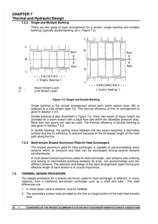
7.2.2 Single and Multiple Banking
There are two types of layer arrangement for a stream: single banking and multiple
banking, (typically double banking, as in Figure 7-2).
Figure 7-2: Single and Double Banking
Single banking is the normal arrangement where each warm stream layer (W) is
adjacent to a cold stream layer (C). The thermal efficiency of this fin arrangement is
given in Section 7.4.5.
Double banking is also illustrated in Figure 7-2. Here, two layers of equal height are
provided for a warm stream with a large flow rate within the allowable pressure drop.
More than two layers can also be used. The thermal efficiency of double banking is
also given in Section 7.4.5.
In double banking, the parting sheet between the two layers becomes a secondary
surface and the fin efficiency is reduced because of the increased length of the heat
path along the fins.
7.2.3 Multi-stream Brazed Aluminium Plate-fin Heat Exchangers
The brazed aluminium plate-fin heat exchanger is capable of accommodating many
streams within its structure and heat can be exchanged among several streams
simultaneously.
A multi-stream brazed aluminium plate-fin heat exchanger, with streams also entering
and leaving at intermediate positions between its ends, can accommodate over ten
different streams. The selection and design of the layer arrangement, layer finning and
effective length of each stream is of crucial importance.
7.3 THERMAL DESIGN PROCEDURE
The design procedure for a brazed aluminium plate-fin heat exchanger is different, in many
respects, from a traditional two-stream exchanger such as a shell and tube. The main
differences are
1. In most cases, several streams must be handled.
2. The secondary surface area provided by the fins is a large portion of the total heat-transfer
area.
2. CHAPTER 7
Thermal and Hydraulic Design
STANDARDS OF THE BRAZED ALUMINIUM PLATE-FIN HEAT EXCHANGER MANUFACTURER'S ASSOCIATION •
•
•
• 47
3. There are a variety of fin types available for giving the best heat transfer and pressure drop
characteristics for each individual stream (see Section 7.6.1).
4. A good sequence of layers is required where each layer is the flow channel for a given
stream with the appropriate choice of finning. This is known as the layer stacking
arrangement and is discussed in Section 7.6.2.
5. There is a strong inter-relationship between the mechanical and thermal-hydraulic design
because key elements in the thermal design, such as fin density, height and thickness, are
governed by the mechanical design.
6. Optimising a design involves working with a large number of variables, and this is best
handled using good software combined with expert knowledge from an experienced
designer.
7. The designer requires much more information to cover the many streams and the greater
detail often required for each stream. Figure 7-3 and Figure 7-4 give examples of
specification sheets which allow for this extra information.
The calculation method given in Section 7.4 is a simple one that effectively converts a multi-
stream heat transfer process into a two stream one. The first step is to generate the
temperature-enthalpy plot (T - Q curve) for all the cold streams and all the warm streams.
Plotting these curves on the same chart is very revealing in showing where close temperature
approaches (temperature pinches) arise, which require special care in design. An overall heat
transfer coefficient is also calculated which combines the individual heat transfer coefficients
for all the streams.
It is stressed that this calculation method is an approximation which can provide good solutions
for simpler heat transfer processes. More rigorous calculation methods are available, which
take into account the detailed variations from stream to stream including the temperature
differences between individual parting sheets. An experienced designer should therefore be
consulted at an early stage in detailed design.
7.4 THERMAL RELATIONS
7.4.1 Basic Heat Transfer Relation
The required surface area of a brazed aluminium plate-fin heat exchanger can be
obtained from:
MTD
Q
UAr = (1)
where
U : Overall heat transfer coefficient between streams (W/m2
K)
Ar : Required overall effective heat transfer surface (m2
)
Q : Heat to be transferred (W)
MTD : Mean temperature difference between composite or combined streams (K)
3. CHAPTER 7
Thermal and Hydraulic Design
48 •
•
•
• STANDARDS OF THE BRAZED ALUMINIUM PLATE-FIN HEAT EXCHANGER MANUFACTURER'S ASSOCIATION
Figure 7-3: Typical Specification Sheet
4. CHAPTER 7
Thermal and Hydraulic Design
STANDARDS OF THE BRAZED ALUMINIUM PLATE-FIN HEAT EXCHANGER MANUFACTURER'S ASSOCIATION •
•
•
• 49
Figure 7-4: Typical Specification Sheet
5. CHAPTER 7
Thermal and Hydraulic Design
50 •
•
•
• STANDARDS OF THE BRAZED ALUMINIUM PLATE-FIN HEAT EXCHANGER MANUFACTURER'S ASSOCIATION
7.4.2 MTD and UA r
The MTD can be obtained by calculating the logarithmic mean temperature difference
(
LMTD) in each section where both warm and cold T - Q curves are linear.
Equation (1) becomes:
∑
=
i
i
r
LMTD
Q
UA (2)
where
( )
i
i
i
i
i
T
T
T
T
LMTD
∆
∆
∆
−
∆
=
=
+
1
1
ln
(3)
∆T
i ; ∆T
i+
1 : Temperature differences between warm and cold streams at each end of
section i (K).
This LMTD can be used for counter-flow or parallel-flow.
For cross-flow and cross-counter-flow, however, the LMTD must be corrected. Details
are given in Reference (1).
For a multi-stream brazed aluminium plate-fin heat exchanger, the MTD must be
obtained from the two composite temperature-enthalpy curves for the combined warm
and combined cold streams. Further information can be found in References (1) to (4).
7.4.3 Overall Effective Heat Transfer Surface of Exchanger
The overall effective heat transfer surface can be estimated from Equation (4). The
thermal resistance of the parting sheet between the two streams can usually be
ignored primarily because it is made from thin aluminium sheet.
∑
∑
+
=
ci
wi
d A
A
UA )
(
1
)
(
1
1
0
0 α
α
(4)
where
α0 : Effective heat transfer coefficient of a stream (W/m2
K)
A : Effective heat transfer surface of a passage or layers of a stream (m2
)
Ad : Designed (or estimated) overall effective heat transfer surface (m2
)
suffix wi, ci : Warm or cold stream i
7.4.4 Effective Heat Transfer Coefficient of Each Stream
The heat transfer coefficient of each stream can be estimated from Equation (5).
3
/
2
Pr
p
mC
jG
=
α (5)
where
α : Heat transfer coefficient of a stream (W/m2
K)
j : Colburn factor for a finned passage (-)
Gm : Mass flux of a stream (kg/m2
s)
C
p : Specific heat capacity of a stream at constant pressure (J/kg K)
Pr : Prandtl Number of a stream (-)
6. CHAPTER 7
Thermal and Hydraulic Design
STANDARDS OF THE BRAZED ALUMINIUM PLATE-FIN HEAT EXCHANGER MANUFACTURER'S ASSOCIATION •
•
•
• 51
The effective heat transfer coefficient of each stream, α0
, can be estimated from
Equation (6) which takes the fouling resistance into account.
r
+
=
α
α
1
1
0
(6)
where
r : Fouling resistance of a stream (m2
K/W)
Equation (5) can be used for single phase streams, i.e. all vapour or all liquid flow. For
two-phase condensing or vaporising flows, various equations are available for
predicting the two-phase heat transfer coefficient; given for example in Reference (4).
A manufacturer, however, will use calculation methods based on experience with two-
phase streams.
The Colburn factor, j, is highly dependent on the type of fin, its nominal geometry and
details of manufacture, as well as the Reynolds Number of the stream. Information
about the Colburn factor j can also be obtained from Reference (2).
Heat transfer coefficients of each stream must be calculated locally where the
thermodynamic and/or physical properties of the stream change rapidly, for example, at
a phase-change or in the super-critical state. For these conditions, a step-by-step
calculation along the stream will be necessary.
7.4.5 Heat Transfer Surface of Each Passage
The effective heat transfer surface area for a passage, A, can be estimated from
Equation (7) for single banking and Equation (9) for double banking:
2
1
1
A
A
A φ
η
+
= (7)
for single banking
( )
2
2
tanh
1
/
/
β
β
=
η (8)
+
+
= 2
1
2
1
2
1
2
1
A
A
A
A φ
η (9)
for double banking
+
−
γ
+
β
=
η
1
1
1
2
B
B
(10)
where
5
0
2
.
m
o
t
h
λ
α
=
β (11)
−
β
=
γ t
n
h
1
2
(12)
β
γ
−
γ
+
= 2
1
1
e
B (13)
A1 : Primary heat transfer surface of a stream (Figure 7-1) (m2
)
A2 : Secondary heat transfer surface of a stream (Figure 7-1) (m2
)
η1 : Passage fin efficiency for single banking (-)
η2 : Passage fin efficiency for double banking (-)
7. CHAPTER 7
Thermal and Hydraulic Design
52 •
•
•
• STANDARDS OF THE BRAZED ALUMINIUM PLATE-FIN HEAT EXCHANGER MANUFACTURER'S ASSOCIATION
h : Passage fin height (m)
t : Passage fin thickness (m)
n : Passage fin density (m-1
)
αo : Effective heat transfer coefficient of a stream (W/m2
K)
φ : Unperforated fraction [1 - (percentage perforation)/100] (-)
λm : Thermal conductivity of fin material (aluminium) (W/m K)
7.4.6 Rough Estimation of the Core Volume
To obtain a quick indication of the heat exchanger volume required for a certain duty,
the following simple relation may be used:
C
MTD
Q
V
/
= (14)
where
V : Required volume of heat exchanger or heat exchangers (without headers)(m3
)
Q : Overall heat duty (W)
MTD : Mean temperature difference between streams (K)
C : Coefficient; 100,000 for hydrocarbon application (W/m3
K)
50,000 for air separation application
The values of 100,000 and 50,000 represent the product, U Ad
, assuming an overall
heat transfer coefficient of 200 W/m2
K and 100 W/m2
K respectively, and a mean
geometric heat transfer surface density of 500 m2
/m3
.
The weight of a complete heat exchanger may be assumed to be 1000 kg per unit core
volume (m3
). This value varies in practice between 650 and 1500 kg /m3
.
7.5 HYDRAULIC RELATIONS
The purchaser usually specifies the allowable pressure loss for each stream, within the
manufacturer's scope of supply.
In the hydraulic design of the heat exchanger, the finning and passages are chosen to meet
this pressure loss requirement. In order to ensure uniform flow distribution of a stream among
its passages, the components of the pressure drop are evaluated. Uniform distribution of a
stream over the width of a layer is provided by good design of the distributors.
7.5.1 Components of Pressure Loss
The individual pressure losses within a heat exchanger typically consist of (See Figure
7-5):
1. Expansion loss into the inlet header
2. Contraction loss at the entry to the core
3. Loss across the inlet distributor
4. Loss across the heat transfer length
5. Loss across the outlet distributor
6. Expansion loss into the outlet header
7. Contraction loss into the outlet nozzle
8. CHAPTER 7
Thermal and Hydraulic Design
STANDARDS OF THE BRAZED ALUMINIUM PLATE-FIN HEAT EXCHANGER MANUFACTURER'S ASSOCIATION •
•
•
• 53
Figure 7-5: Pressure Loss Components
Additional pressure losses in piping and/or manifolding outside the manufacturer's
scope of supply are to be accounted for by the purchaser.
General methods for predicting these pressure losses are given in Reference (4).
Manufacturers make use of their experience to select the most appropriate method of
estimating the losses given in Items 1 to 7 above.
7.5.2 Single-Phase Pressure Loss
The frictional pressure loss across a plate-fin passage and at any associated entry, exit
and turning losses, can be expressed by:
+
=
∆
ρ
ρ 2
2
d
f
4
2
2
h
m
m
p G
K
G
l
P (15)
where
f : Fanning friction factor (-)
l p : Passage length (m)
d
h : Hydraulic diameter of passage (m)
Gm : Mass velocity (mass flux) of stream (kg/m2
s)
ρ : Density of a stream (kg/m3
)
K : Expansion, contraction or turning loss coefficient (-)
∆P : Overall pressure drop (Pa)
9. CHAPTER 7
Thermal and Hydraulic Design
54 •
•
•
• STANDARDS OF THE BRAZED ALUMINIUM PLATE-FIN HEAT EXCHANGER MANUFACTURER'S ASSOCIATION
Note: By convention, the upstream mass flux is used for estimating expansion losses
and the downstream for contractions.
7.5.3 Two-Phase Pressure Loss
In brazed aluminium plate-fin heat exchangers with two-phase streams where fluid
quality and physical properties are changing, it is necessary to divide the heat
exchanger into suitable increments of length in order to assess the overall pressure
gradient simultaneously with the thermal design calculations.
The pressure gradient in a two-phase flow can be divided into three components:
• The frictional component,
• The static head component,
• The accelerational component.
Each manufacturer uses suitable design correlations for estimating these components
from experience. General estimating methods are given in Reference (4).
7.6 GENERAL CONSIDERATIONS IN THE THERMAL AND HYDRAULIC DESIGN
7.6.1 Choice of Fin Geometry
Each fin must conduct the required amount of heat and also withstand the design
pressure at the design temperature as a structural component.
Fin geometry is therefore selected to meet both requirements. Details of the required
structural performance are given in Chapter 5. Details of the fin's required thermal
performance are given earlier in Section 7.4.4.
The choice of fin will also influence the most economical design of an exchanger for a
specific application. Table 7-1 provides general information on common applications for
each type of fin (see Figure 1-6, Chapter 1).
Table 7-1: Common Applications for each Type of Fin
Features
Corrugation Description Application
Relative pressure
drop
Relative heat
transfer
Plain Straight For general use lowest lowest
Perforated Straight with small
holes
Most frequently used
for any purpose.
Sometimes used for
the "hardway" finning
low low
Serrated Straight, offset half a
pitch - usually about
every 3-4 mm
Frequently used,
especially for low
pressure gas
streams in air
separation plants
highest highest
Herringbone or
long-lanced
serrated
Smooth but in waves
of about 10 mm
pitch, or serrated with
long serration pitch
Often used for gas
streams with low
allowable pressure
drop
high high
10. CHAPTER 7
Thermal and Hydraulic Design
STANDARDS OF THE BRAZED ALUMINIUM PLATE-FIN HEAT EXCHANGER MANUFACTURER'S ASSOCIATION •
•
•
• 55
7.6.2 Layer Stacking Arrangement
With multi-stream heat exchangers, the choice of the stacking sequence or layer-
pattern, must take into account the local heat balance among streams and any local
non-linearity of the Enthalpy-Temperature Curves of each stream. A thermally well-
balanced stacking arrangement would result in a nearly uniform metal temperature at
any cross section of the heat exchanger, thus allowing the detailed design to proceed
with the assumption of a common wall temperature.
The deviations from a uniform metal temperature can be evaluated by using a more
detailed (layer-by-layer) analysis, taking into account heat being transferred by metal
conduction between non-adjacent layers.
11.
12. Chapter 8
Recommended Good Practice
STANDARDS OF THE BRAZED ALUMINIUM PLATE-FIN HEAT EXCHANGER MANUFACTURER'S ASSOCIATION •
•
•
• 57
8 RECOMMENDED GOOD PRACTICE
8.1 THERMAL STRESSES WITHIN BRAZED ALUMINIUM PLATE-FIN HEAT EXCHANGERS
8.1.1 Introduction
As with any pressurised heat exchanger, stresses in each component of a brazed
aluminium plate-fin heat exchanger must be maintained within allowable limits.
Pressure loads, externally applied loads (e.g. piping forces and moments), and
thermally induced loads produce stresses which must be maintained within permissible
limits to prevent component damage or failure.
Manufacturers design each brazed aluminium plate-fin heat exchanger for the intended
design pressure loads; users are provided with details of allowable external loads that
may be exerted on the exchanger. A margin above the stresses created by these loads
is made available by the manufacturer for thermally-induced loads which may occur in
service. In this section the mechanism by which thermal stresses are induced is
explained.
Recommendations are given for the measures to be taken in the operation of brazed
aluminium plate-fin heat exchangers so that the overall combined stresses remain
within allowable limits during standard and non-standard operating conditions.
8.1.2 Failure Mechanism
The components of a brazed aluminium plate-fin heat exchanger are relatively close
and rigidly connected in all directions to each other. As a result, conditions which
generate large local metal temperature differences in and between the components of
its structure, will cause significant thermal stress in these components.
Local metal temperature differences result from the components, or portions of the
components, warming or cooling at different rates in response to a thermal input
(change). These differences produce a transient differential expansion or contraction
within or between the components; mechanical restraint to these thermally-induced
structural movements results in thermal stress in the components. If the local metal
temperature differences are large, the combined thermally-induced stresses and other
stresses from imposed loads can exceed the yield stress and possibly the ultimate
stress of the material.
Temperature differences between adjacent parts of a heat exchanger, having the
potential to produce significant thermal stresses, can arise from:
1. Continuously unsteady operating conditions: for example, large flow fluctuations;
unstable flow in boiling channels; inadequate plant control systems.
2. Transient operating conditions: for example, start-up; shut-down; plant upsets;
deriming; cool-down and warm-up; etc.
An example of the creation of thermal stress is illustrated by the quick opening of a
valve. If this action allows a significant quantity of cold fluid with a high thermal capacity
to enter a warm heat exchanger, then those parts of the heat exchanger which can lose
heat rapidly will contract quickest. The finning in the region of the inlet port would thus
contract more quickly than the side bars on either side of the port; tensile thermal
stress would be created within the fins and compressive stress in the side bars. These
stresses will diminish as temperature differences decrease and thermal equilibrium is
restored. Thermally-induced failures can also occur in other components of a heat
exchanger apart from the fins. The next most susceptible component is the parting
sheet.
Continuously unsteady operating conditions, as described above, can generate cyclic
stresses exceeding the yield strength, and failure by fatigue may result.
13. Chapter 8
Recommended Good Practice
58 •
•
•
• STANDARDS OF THE BRAZED ALUMINIUM PLATE-FIN HEAT EXCHANGER MANUFACTURER'S ASSOCIATION
During transient operating conditions, if the combined stresses exceed the ultimate
tensile strength of the material, components may fail.
8.1.3 Recommendations
To reduce the possibility of component damage or failure during the operational
conditions described above, the following recommendations are made:
1. Limit the pressure and external loads to those allowed (stated) by the
manufacturer.
2. As with any heat exchanger, bring the brazed aluminium plate-fin exchanger to or
from operating or derime conditions slowly to avoid excessive thermal stress. This
is of particular importance when introducing a liquid or two-phase stream due to
the heat capacity of the stream and its ability to transfer heat rapidly to or from the
components. Recommended rates for start-up and shut-down, cool-down, warm-
up, deriming, etc. are presented in Chapter 4.
3. Limit the temperature differences between adjacent streams at any point in the
heat exchanger to those recommended in Chapter 5 or by the manufacturer.
Temperature differences recommended in Chapter 5 are general to all brazed
aluminium plate-fin heat exchangers. Other recommendations may be provided by
the manufacturer when supplying a heat exchanger for a particular application.
4. Exercise particular care in applications where a liquid is totally vaporised within the
heat exchanger. Boiling to total dryness can produce large temperature
differences and also induce flow instabilities. The manufacturer's recommended
allowable temperature differences for these applications must be strictly adhered
to. Also, the design of the process plant must ensure that stable flow occurs.
5. Design and operate the plant equipment and piping connected to the heat
exchanger to prevent flow excursion and instabilities (for example, intermittent
slugging of liquid to the exchanger). This is particularly important with boiling
streams.
6. Limit cyclic or frequently repeated temperature fluctuations of any stream to ±1°
C
per minute.
8.1.4 Summary
Brazed aluminium plate-fin heat exchangers are robust exchangers which are very
tolerant of large steady-state stream-to-stream temperature differences. Being
relatively compact and rigid structures, brazed aluminium plate-fin heat exchangers are
susceptible to damage if subjected to transient or continuously unsteady operating
conditions which produce excessive thermal stressing. Excessive thermal stressing can
be avoided by following the precautions (recommendations) outlined above, thus
helping to ensure long life of the heat exchanger.
8.2 FOULING AND PLUGGING OF BRAZED ALUMINIUM PLATE-FIN HEAT EXCHANGERS
8.2.1 Fouling
Fouling is generally not encountered for processes in which brazed aluminium plate-fin
heat exchangers are traditionally used: air separation; hydrocarbon separation and
liquefaction of gases.
In the case where a degradation of thermal performance is observed with little or no
change in pressure drop of the product, fouling may be suspected.
Recommended actions are as follows:
14. Chapter 8
Recommended Good Practice
STANDARDS OF THE BRAZED ALUMINIUM PLATE-FIN HEAT EXCHANGER MANUFACTURER'S ASSOCIATION •
•
•
• 59
8.2.1.1 Prevention
Before deciding on the use of brazed aluminium plate-fin heat exchangers,
the fluid conditions have to be examined for the presence of solids, foreign
particles forming deposits during operation of the heat exchanger, especially
in low temperature regions.
It is important also to consider fouling that may arise from contaminants in
the process fluids. A typical example is the use of seal oil with refrigerant
streams, which could deposit as a solid film on the fin surfaces and reduce
the thermal performance of the heat exchanger.
WARNING: GASES CONTAINING TRACES OF NOx MUST NOT BE
USED: NOx WILL ACCUMULATE IN THE CRYOGENIC PORTION OF THE
EQUIPMENT. EXPERIENCE HAS SHOWN THAT SUCH PRODUCTS
CANNOT BE REMOVED FROM THE INTERIOR OF THE EQUIPMENT
AND MAY SUDDENLY EXPLODE DURING WARMING UP OF THE
PLANT.
8.2.1.2 Remedial action
If the liquid/solid transformation of the fouling agent is reversible with
temperature, changing the operating conditions of the heat exchanger and
thus warming up the fouled zone may be sufficient to eliminate the deposits.
In cases where this technique is not effective, solvent cleaning may be used.
Brazed aluminium plate-fin heat exchangers can be modified or designed to
incorporate solvent injection system thus allowing flushing of the
contaminated surfaces.
8.2.2 Plugging
Plugging is defined as being the obstruction of fin channels inside a brazed aluminium
plate-fin heat exchanger as a result of solid particles having entered the unit.
The effect of plugging on a brazed aluminium plate-fin heat exchanger may be very
serious for its thermal performance since, generally, the plugging medium will not be
distributed evenly to all passages, and uniformly within the width of the passages and
will thus cause severe maldistribution. Simultaneously, the pressure drop of the
plugged stream will increase significantly.
WARNING: IN THE CASE OF EXTREMELY SEVERE PLUGGING, THE SAFETY
ASPECTS OF THE PLANT MUST BE CONSIDERED.
8.2.2.1 Prevention
Plugging of brazed aluminium plate-fin heat exchangers can be prevented by
following these recommended actions.
- The end closures of brazed aluminium plate-fin heat exchangers should
always be maintained during manufacture until the connection of nozzles
or flanges to the plant pipework.
- The cleanliness of the connecting pipes should be checked to make sure
that rust, debris, dust, etc. can not enter the heat exchanger.
- Filters on the feed streams should be installed at any location where
there is a possibility of contaminating the process fluid.
Recommendations are provided by manufacturers as to the mesh size,
and filter types, etc., depending upon maintenance considerations, for
specific applications. A mesh size of 177 microns (80 Tyler) is capable of
covering most applications
15. Chapter 8
Recommended Good Practice
60 •
•
•
• STANDARDS OF THE BRAZED ALUMINIUM PLATE-FIN HEAT EXCHANGER MANUFACTURER'S ASSOCIATION
8.2.2.2 Remedial action
Should the heat exchanger be significantly plugged for any reason (absence
of filter, wrong cleaning procedure of plant pipework, failure of filtering
equipment, etc.), the consequences on both the thermal and pressure drop
performance will be obvious.
The plugged stream can generally be identified quickly and corrective action
be planned to be taken during a shut-down of the plant.
The mechanical methods to remove plugging from a brazed aluminium plate-
fin heat exchanger require the use of an air or nitrogen gas discharge from
the exchanger:
- Either back-blow the plugged stream, having installed a bursting disc at
the inlet and pressurising up to the rupture of the disc.
(This operation has to be repeated until no particles are observed being
discharged).
- or install a special "deplugger" at the outlet of the heat exchanger, made
of a volume of air under pressure and a quick-opening valve, to produce
a shock wave inside the heat exchanger core.
In the case of severe plugging, a deplugging action may be undertaken on
every passage, having connected the "deplugger" successively to each
individual passage.
The use of a solvent and gas bubbling uses the bubbles generated inside the
liquid which fills the structure, and these provide the mechanical energy to
dislodge the particles.
8.3 CORROSION
Brazed aluminium plate-fin heat exchangers are satisfactorily used in many processes without
experiencing corrosion problems. However, as with any heat exchanger, when corrosion is
possible, caution must be exercised both on the choice of process fluids and the environment
to which the brazed aluminium plate-fin heat exchanger is exposed. Purchasers/operators
should contact the manufacturer to determine the best course of action to avoid corrosion
problems.
WARNING: CAUTION MUST BE EXCERCISED BOTH IN THE CHOICE OF PROCESS
FLUIDS AND THE ENVIRONMENT TO WHICH HEAT EXCHANGERS ARE EXPOSED
WHEN CORROSION IS POSSIBLE.
8.3.1 Process Environments Containing Water
The corrosion processes due primarily to water or which involve water as one of the
contributors will stop or be unable to start in those portions of the brazed aluminium
plate-fin heat exchangers which are operating below the freezing point of water. This
may not be 0o
C due to water purity variations and supercooling phenomena. Above
the freezing point, for example during de-riming, consideration must be given to other
factors. Water service can be grouped into 3 categories:
8.3.1.1 Water service in neutral environments
Brazed aluminium plate-fin heat exchangers can be used extensively in the
processing of many materials containing water provided the water is and
remains relatively neutral in character while within the exchanger (pH of 6 to
8) even in the presence of halides. The compatibility of the aluminium heat
exchanger with a process stream containing neutral water can be affected by
factors such as the degree of heavy metals contained within the process
stream and deposit formation.
16. Chapter 8
Recommended Good Practice
STANDARDS OF THE BRAZED ALUMINIUM PLATE-FIN HEAT EXCHANGER MANUFACTURER'S ASSOCIATION •
•
•
• 61
For example, aluminium heat exchangers used together with copper and its
alloys, or with other heavy metals such as iron, nickel and lead, should be
avoided unless an inhibitor is used to protect the aluminium heat exchanger
components. The pitting corrosion resulting from the use of process streams
containing heavy metals is usually less severe when the soluble ions of these
heavy metals are decreased. Consequently, the presence of heavy metals in
acidic or neutral water service process streams in conjunction with aluminium
plate-fin heat exchangers will be more detrimental than in alkaline process
streams. Austenitic stainless steels are very acceptable for use in
combination with aluminium plate-fin heat exchangers in neutral water
service process streams.
8.3.1.2 Water service in acidic environments
Aluminium alloys commonly used in heat exchangers are resistant to acidic
process streams or local acidic conditions in the 4.5 to 6.0 pH range.
However, an inhibitor should be used in this pH range if heavy metals or
halides are present in the process stream. Below a pH of 4.5, corrosion can
initiate by breakdown of the protective oxide film and by galvanic coupling
between components or areas of the aluminium heat exchanger and other
more noble metals in the process equipment. Structurally significant
corrosion can result from direct chemical conversion of the exposed nascent
aluminium after the protective oxide has broken down. As is the case with
neutral environments, the formation of deposits can change both the
environmental conditions at which corrosion begins and the severity of the
attack once the corrosion begins.
8.3.1.3 Water service in alkaline environments
Aluminium heat exchanger alloys have excellent corrosion resistance in
mildly alkaline environments (pH of 8 to 9). An alkaline process stream may
discolour the surface of the aluminium components, but this darkening of the
surface is only superficial and will not effect the structural or operational
integrity of the heat exchanger. The use of Aluminium Plate-Fin Heat
Exchangers in more severe alkaline environments (pH > 9) should be done
only after a very careful analysis and consideration of the chemical process
streams involved. Other factors such as process and impurity concentrations
and temperatures within the operating environment to which the equipment
will be subjected also need to be given some consideration.
To summarise, the pH value should remain between 4.5 and 8.5 and the presence of
halides and heavy metal ions should be avoided.
8.3.2 Process Environments Containing Mercury
In general, mercury will not react with aluminium unless it is allowed to exist in contact
with the heat exchanger in its liquid state and there is water present. If these
conditions exist within a heat exchanger, then mercury contamination can result in
problems. This attack is most severe when coupled with another corrosion process.
Another possible problem resulting from mercury in the process stream affects
aluminium alloys that contain a high level of magnesium. A rapid reaction of mercury
with a magnesium-based secondary phase within the aluminium can take place in the
absence of water. If features are not designed into the equipment to address this
problem and conditions are conducive, mercury corrosion cracking can occur and
propagate at substantially lower levels of stress than that required if mercury were not
present.
17. Chapter 8
Recommended Good Practice
62 •
•
•
• STANDARDS OF THE BRAZED ALUMINIUM PLATE-FIN HEAT EXCHANGER MANUFACTURER'S ASSOCIATION
Many brazed aluminium plate-fin heat exchangers are able to operate successfully with
fluids containing mercury by using precautions that are available. Purchasers can
remove mercury from the feed gas with commercially available systems. Operators
may also use special shutdown procedures (nitrogen blanketing) to restrict moisture
and avoiding, for metallurgical reasons, elevating temperatures above 100 °C for long
periods, for example during de-riming operations.
Manufacturers can offer several options when mercury service is specified. Design
features can eliminate the build up or pocketing of mercury. Often it is possible to
avoid the use of susceptible alloys. When those choices are not possible, precautions
are available either to isolate or protect the high-magnesium containing alloys from
mercury attack.
8.3.3 Atmospheric or Environmental Corrosion
Aluminium plate-fin heat exchangers will generally not suffer to any structurally
appreciable extent from atmospheric corrosion. Slight cosmetic corrosion may result if
the exchangers are left outside in a humid environment with temperature changes that
result in condensation of the humidity on the aluminium surfaces.
Extra precautions should be taken if the exchangers are exposed to an environment
containing appreciable quantities of salt spray or salt air, for example, during extended
open storage at site locations in coastal areas or during ocean transport. In the case of
ocean freight without seaworthy packing; e.g. transport of exchanger batteries, it is
recommended that, immediately after arrival on site, all surfaces be washed with water
with a chlorine content < 25 ppm. Manufacturers should be contacted regarding the
detailed procedures to be used to wash the core. After washing, all surfaces need to be
dried thoroughly.
Since it is difficult to insure the leak tightness of any heat exchanger insulation system
it is important that safety systems which use water to control fire hazards do not
expose the heat exchangers to sea, brackish or other forms of salt water. This water
could become trapped between the heat exchanger insulation and the heat exchanger
metal surfaces resulting in corrosion of the exposed surfaces. Even tap water can
result in corrosion under these conditions, and manufacturers should be contacted
regarding procedures to be used to dry the cores.
8.3.4 Other Services
There are many possible service environments for satisfactory operation of brazed
aluminium plate-fin heat exchangers. Not all corrosion risks are addressed in this
guideline. If there is uncertainty about the fluid and/or process conditions, contact the
manufacturer for specific advice.
18. Notation
STANDARDS OF THE BRAZED ALUMINIUM PLATE-FIN HEAT EXCHANGER MANUFACTURER'S ASSOCIATION •
•
•
• 63
Notation
SI IMPERIAL
A Effective heat transfer surface of a passage or layer m2
ft2
Ad Designed or estimated overall effective heat transfer surface m2
ft2
Ar Required overall effective heat transfer surface m2
ft2
A1 Primary heat transfer surface of a stream m2
ft2
A2 Secondary heat transfer surface of a stream m2
ft2
B Defined by Equation (13), Chapter 7 - -
C Coefficient, defined by Equation (14), Chapter 7 W/m3
K Btu/ft2
F
C
p Specific heat J/kg K Btu/lb F
d
h Hydraulic diameter of passage m ft
f Fanning friction factor - -
F Force N lb
Gm Mass flux/velocity of a stream kg/m2
s lb/ft2
hr
h Fin height mm in
H Stacking height of a core mm in
j Colburn factor for a finned passage - -
K Expansion/contraction/turning loss coefficient - -
l p Passage length mm in
ls Serration length or distance between crests on herringbone fins mm in
L Core length mm in
LMTD Logarithmic mean temperature difference K F
M Moment Nm lb ft
MTD Mean temperature difference K F
n Fin density m-1
in-1
p Fin pitch mm in
Pr Prandtl number - -
Q Overall heat duty; heat to be transferred W Btu
r Fouling resistance m2
K/W ft2
F hr/Btu
s Distance between the extreme bolts in a given plane mm in
t Fin thickness mm in
U Overall heat transfer coefficient between streams W/m2
K Btu/hr ft2
F
V Volume of heat exchanger or exchangers m3
ft3
W Width of core mm in
X Required clearance distance mm in
Greek
αl Coefficient of linear expansion at average temperature m/m K ft/ft F
αo Effective heat transfer coefficient of a stream W/m2
K Btu/hr ft2
F
α Heat transfer coefficient of a stream W/m2
K Btu/hr ft2
F
β Defined by Equation (11), Chapter 7 - -
γ Defined by Equation (12), Chapter 7 - -
∆P Overall pressure drop N/m2
(Pa) lb/in2
∆T Local temperature difference between warm and cold streams K F
∆T
R Temperature range at support K F
η1 Passage fin efficiency for single banking - -
η2 Passage fin efficiency for double banking - -
λm Thermal conductivity of fin material W/m K Btu/hr ft F
ρ Density of stream kg/m3
lb/ft3
φ Unperforated fraction of fin - -
Subscripts
c Cold stream w Warm stream
i Section x,y,z Direction
19.
20. References
References
STANDARDS OF THE BRAZED ALUMINIUM PLATE-FIN HEAT EXCHANGER MANUFACTURER'S ASSOCIATION
STANDARDS OF THE BRAZED ALUMINIUM PLATE-FIN HEAT EXCHANGER MANUFACTURER'S ASSOCIATION •
•
•
•
•
•
•
• 65
65
References
References
(1)
(1) Ward, J.A., "Ef
Ward, J.A., "Effectiveness-NTU Relationsh
fectiveness-NTU Relationships", Data Item 86018, Engi
ips", Data Item 86018, Engineering Scienc
neering Sciences Data
es Data
Unit, London, 1986.
Unit, London, 1986.
(2) Kays, W.M. and London, A.L., "Compact Heat Exchangers", McGraw Hill, New York, Third
(2) Kays, W.M. and London, A.L., "Compact Heat Exchangers", McGraw Hill, New York, Third
Edition, 1984.
Edition, 1984.
(3)
(3) Taborek, J. and Spalding, D.B., "Heat Exchanger Design
Taborek, J. and Spalding, D.B., "Heat Exchanger Design Handbook", Hemisphe
Handbook", Hemisphere Publishing
re Publishing
Corporation, 1983.
Corporation, 1983.
(4)
(4) Taylor, M.A., "Plate-Fin He
Taylor, M.A., "Plate-Fin Heat Exchangers - Guid
at Exchangers - Guide to Their Specification
e to Their Specification and Use", HTFS, 392
and Use", HTFS, 392.7
.7
Harwell, Oxon, OX11 0RA, UK. 1987.
Harwell, Oxon, OX11 0RA, UK. 1987.
21.
22. Index
Index
STANDARDS OF THE BRAZED ALUMINIUM PLATE-FIN HEAT EXCHANGER MANUFACTURER'S ASSOCIATION
STANDARDS OF THE BRAZED ALUMINIUM PLATE-FIN HEAT EXCHANGER MANUFACTURER'S ASSOCIATION •
•
•
•
•
•
•
• 67
67
Index
Index
Accep
Acceptabl
table
e Flui
Fluids
ds .................
..................................
..........................
.........2
2
AD-M
AD-Merkbl
erkblätter
ätter .................
...................................
............................
..........35
35
Aftercooler......................................................2
Aftercooler......................................................2
Air
Air Separa
Separation Unit(ASU)......................
tion Unit(ASU)................................
..........2
2
Air
Air test
test................
..................................
....................................
........................
......36
36
Ammon
Ammonia
ia..................
....................................
..................................
................2
2, 3
, 3
Angle
Angle Bracket
Bracket Support
Support Arrangement
Arrangement ............
............ 26
26
Argon
Argon...............................................................3
...............................................................3
AS
AS 1210.....
1210.....................
...............................
..............................
....................
.....35
35
ASME V
ASME VIll, Di
Ill, Div. 1
v. 1 .................
...................................
.........................
.......35
35
Asph
Asphyxia
yxiation
tion..................
....................................
...............................
.............32
32
Atmosp
Atmospheri
heric
c Corro
Corrosion
sion..............
..............................
...................
...62
62
Banking
Banking
Mul
Multiple
tiple ................
..................................
....................................
...................
.46
46
Sing
Single.........................
le...........................................
...............................
.............46
46
Beams
Beams
Suppo
Support
rt ...............
...............................
................................
......................
......23
23
Bloc
Block (core)
k (core) .................
...................................
...................................4
.................4
Bloc
Blocking of Laye
king of Layers
rs ..................
....................................
......................
....22
22
Burst
Burst test
test metho
method.........
d..........................
.................................
................41
41
Butane
Butane.............................................................3
.............................................................3
Cap sheet
Cap sheet...............
.............................
............................
..........................
............4
4
Cap
Cap Sheets.......
Sheets......................
.............................
............................
...............
.41
41
Carbo
Carbon
n Diox
Dioxide......................
ide....................................
.....................
.......2,
2,3
3
Carbo
Carbon
n Mon
Monoxide
oxide..............
...........................
.........................
............2,
2, 3
3
Cascade Cooling
Cascade Cooling...............................................3
...............................................3
Chille
Chillers
rs ..............
............................
............................
.............................
.................
..2
2
Chlorine..........................................................2
Chlorine..........................................................2
Choice of Fin Geometry................................
Choice of Fin Geometry................................54
54
Clean
Cleaning
ing..............
............................
...........................
.....................
........20,
20,59
59
Solvent......................................................59
Solvent......................................................59
CODAP.........................................................35
CODAP.........................................................35
Code Data
Code Data Repor
Reports
ts.............
..........................
..........................
.............19
19
Codes for
Codes for Cons
Constructi
truction
on.............
.........................
....................
........35
35
Coeffi
Coefficient of
cient of Ther
Thermal Expans
mal Expansion
ion..........
.................
.......28
28
Colb
Colburn
urn Facto
Factor
r................
.................................
..............................
.............50
50
Cold Boxe
Cold Boxes
s.................
...................................
..................................
................32
32
Components
Components
of
of an
an Excha
Exchanger......................
nger....................................
....................
......4
4
of Manifolded Exchangers...........................
of Manifolded Exchangers...........................5
5
Condenser
Condenser
Overh
Overhead
ead.............
............................
..............................
........................
.........2
2
Conde
Condensers
nsers..............
............................
.............................
........................
.........2
2
Connection Options
Connection Options
Flanges.......................................................6
Flanges.......................................................6
Stub
Stub Ends
Ends..................
....................................
.................................
...............6
6
Tran
Transitio
sition
n Join
Joints
ts...............
................................
...........................
..........6
6
CONTRAC
CONTRACTUAL
TUAL INFORM
INFORMATION
ATION.................
.................17
17
Cool
Cool-dow
-down
n ..................
....................................
..................................
................31
31
Core
Core (blo
(block)...............................
ck)................................................
.....................
....4
4
Core Volume
Core Volume
Estim
Estimatio
ation
n..................
....................................
...............................
.............52
52
Corros
Corrosion
ion.................
...................................
....................................
...................
.60
60
Acidic Environments..................................
Acidic Environments..................................61
61
Alkaline Environments...............................
Alkaline Environments...............................61
61
Atmospheric or Environmental...................
Atmospheric or Environmental...................62
62
Environments containi
Environments containing Mercury.............
ng Mercury..............
.61
61
Water
Water ................
..................................
....................................
......................
....60
60
Corros
Corrosion
ion Allo
Allowanc
wances
es ..................
...................................38
.................38
Damage........................................................33
Damage........................................................33
Defini
Definition............
tion..............................
....................................
.........................35
.......35
Dephl
Dephlegmat
egmators
ors ..............
............................
............................
...................2
.....2
Depl
Depluggin
ugging..............
g................................
.....................................
....................60
.60
Description
Description
Genera
Generall ..............
..............................
................................
.........................
.........1
1
DESIGN
DESIGN
HYDRA
HYDRAULIC
ULIC ................
..................................
.......................
.....45
45
–
–55
55
THERMAL...........................................
THERMAL...........................................45
45
–
–55
55
Desig
Design
n Code................................
Code.................................................17
.................17
Design Pressures..........................................
Design Pressures..........................................35
35
Desig
Design
n Tempe
Temperatur
rature
e .................
...................................
....................
..37
37
Distributor
Distributor
Centra
Centrall .................
...................................
....................................
...................10
.10
Diago
Diagonal
nal.............
............................
..............................
........................10
.........10
Double Entry/Exit.......................................10
Double Entry/Exit.......................................10
End........
End..........................
....................................
....................................9
..................9
Inter
Intermedia
mediate
te ..................
....................................
..............................9
............9
Mitre..........................................................10
Mitre..........................................................10
Side.............................................................9
Side.............................................................9
Spec
Special
ial .................
...................................
....................................
.....................9
...9
Spli
Split
t Flow.....
Flow.......................
....................................
............................10
..........10
Distri
Distributo
butor
r fins............................
fins..............................................
.....................4
...4
Drawi
Drawings.....................
ngs........................................
..................................
...............18
18
Approval and Change................................18
Approval and Change................................18
for Record
for Record ...............
................................
..................................18
.................18
Infor
Informatio
mation
n .................
...................................
...............................18
.............18
Proprietary Rights......................................19
Proprietary Rights......................................19
Dryin
Drying
g ................
..................................
....................................
.........................20
.......20
Dummy
Dummy Passa
Passages......................
ges.......................................
...................20
..20
Dutch Pressu
Dutch Pressure Vessel Code
re Vessel Code.............
........................35
...........35
Ethane
Ethane ................
..................................
....................................
...........................3
.........3
Ethylene
Ethylene...........................................................3
...........................................................3
Exchanger
Exchanger
bloc
block
k (core
(core)
) ...............
...............................
................................
..................1
..1
cap
cap sheet
sheets.........................
s........................................
..........................1
...........1
inle
inlet
t ports..
ports....................
....................................
.................................1
...............1
laye
layers
rs (pass
(passages
ages)
)................
.................................
........................1
.......1
multi
multi-stre
-stream
am .................
...................................
...............................1
.............1
outle
outlet ports
t ports .................
...................................
.................................1
...............1
parti
parting
ng shee
sheets......................
ts.......................................
........................1
.......1
side
side bars..
bars...................
.................................
.................................
...................1
..1
size......
size........................
...................................
...................................
.....................1
...1
FABRIC
FABRICATION...............
ATION.................................
.........................
.......17
17
–
–22
22
Failure Mechanism........................................
Failure Mechanism........................................57
57
23. Index
68 •
•
•
• STANDARDS OF THE BRAZED ALUMINIUM PLATE-FIN HEAT EXCHANGER MANUFACTURER'S ASSOCIATION
Field Testing.................................................29
Filters ...........................................................31
Fin Corrugations.............................................8
Fin Dimensions...............................................9
Definition.....................................................9
Fins Per Inch (FPI)......................................9
PercentagePerforation...............................9
Fin Geometry
Choice of...................................................54
Fin Types........................................................8
Fins .............................................................. 41
Herringbone................................................8
Perforated...................................................8
Plain............................................................ 8
Serrated......................................................8
Wavy...........................................................8
Fixing Bolts...................................................27
Flange Protection ......................................... 20
Flanges ........................................................ 40
Flow Arrangements ......................................11
Co-Current Flow........................................ 11
Counterflow...............................................11
Cross-Counterflow....................................11
Crossflow..................................................11
Flow Fluctuations..........................................57
Flow Velocities in Nozzles............................39
Fluids
Acceptable..................................................2
Fouling .........................................................58
Fouling Resistance.......................................51
Freeze Spots................................................32
Freon...............................................................3
General Description........................................1
GENERAL DESCRIPTION.......................1
–11
GOOD PRACTICE .................................57
–62
Guarantees...................................................19
Consequential Damage.............................19
Corrosion..................................................19
Thermal and Mechanical........................... 19
Guide Frame
Sliding.......................................................24
Handling.......................................................23
Header
Dome..........................................................7
Inclined Ends..............................................7
Mitred Ends.................................................7
Standard.....................................................7
Header/Nozzle Configurations........................ 6
Headers.......................................... 4, 6, 38, 41
Heat Transfer Coefficient of a Stream........... 50
Heat transfer fins............................................4
Heat Transfer Surface.................................. 47
Height.............................................................4
Stacking......................................................1
Helium.............................................................3
Helium Leak Test..........................................34
Helium Recovery...............................................3
Helium test....................................................36
Hexane ............................................................3
HYDRAULIC DESIGN ............................45
–55
Hydrogen .........................................................3
Hydrogen Sulphide.........................................2
Inactive Areas...............................................20
Injury.............................................................33
Inspection.....................................................17
Manufacturer’s ..........................................17
Purchaser’s...............................................17
Third Party ................................................17
INSTALLATION......................................23
–34
Insulation......................................................30
Japanese HPGS Law....................................35
Layer Arrangements .....................................40
Leak Detection..............................................32
Leak Rate .....................................................37
Leak Test......................................................36
Air .............................................................36
Helium.......................................................36
Length ............................................................4
Lifting............................................................23
Lifting Devices ..............................................21
Lifting lugs ....................................................21
Limits of Use
Maximum working pressure.........................2
Maximum working temperature...................2
Minimum design temperature......................2
Liquefaction......................................................3
Liquefied Natural Gas ........................................3
Liquefied Natural Gas (LNG)...............................3
Liquefied Petroleum Gas (LPG)...........................3
Liquefiers........................................................2
Liquified Natural Gas (LNG)............................2
Logarithmic Mean Temperature Difference...50
Main Exchanger..............................................2
Maintenance.................................................32
MAINTENANCE......................................23
–34
MATERIALS...........................................43
–44
Materials of Construction ........................35, 43
MeanTemperature Difference......................47
MECHANICAL STANDARDS .................35
–42
Mercury.....................................................3,61
Metal Temperature Limitations......................37
Methane...........................................................3
Module Construction.......................................6
Mounting Bolts..............................................27
MTBE ..............................................................3
Multi-Component Refrigerants...........................3
Multiple Banking ...........................................46
Multi-Stream .................................................46
Nameplate....................................................17
Data..........................................................18
Manufacturer’s ..........................................17
Purchaser’s...............................................18
24. Index
STANDARDS OF THE BRAZED ALUMINIUM PLATE-FIN HEAT EXCHANGER MANUFACTURER'S ASSOCIATION •
•
•
• 69
Structure...................................................17
Supplementary Information .......................18
Natural Gas Processing (NGP)...................2, 3
Nitrogen...........................................................3
Nitrogen Dioxide.............................................2
Nitrogen Rejection Unit (NRU) ............................3
NOMENCLATURE.................................... 1
–11
Nomenclature of the Components ..................4
Nonconformity Rectification..........................21
Non-Destructive Testing ...............................29
Nozzle
Inclined .......................................................7
Radial..........................................................7
Tangential...................................................7
Nozzle loadings............................................39
Nozzle Type....................................................6
Nozzles...........................................4,6, 39, 41
Flow Velocities in ......................................39
Loadings ...................................................39
Operation......................................................31
OPERATION ..........................................23
–34
Overall Heat Transfer ...................................47
Overhead Condenser .....................................2
Oxygen ............................................................3
Particulate Matter..........................................31
Parting sheet ..................................................4
Parting Sheets..............................................41
Pentane ...........................................................3
Petrochemical Production...................................3
Piping .............................................................6
Plant Upsets.................................................57
Plugging .................................................58, 59
from dust.....................................................3
from molecular sieve dust ...........................3
from particulates..........................................3
Pressure Loss...............................................52
Single-Phase............................................. 53
Two-Phase................................................54
Pressure Relief Device .................................31
Pressure Relieving Devices..........................31
Pressure Test.........................................33,36
Hydrostatic................................................36
Pneumatic.................................................36
Pressure Testing ..........................................29
Pressure Vessel ...........................................41
Pressurising..................................................20
Primary Heat Transfer Surface .....................45
Production Process.......................................40
Proof Pressure Testing.................................29
Propane...........................................................3
Propylene.........................................................3
Pulsing..........................................................31
Raccolta .......................................................35
Rare Gases ......................................................3
Reboilers ........................................................2
Rectification
Leak..........................................................22
Nonconformity...........................................21
Rectification of Leaks....................................22
Refrigeration Systems........................................3
Repair of Leaks.............................................34
Reversing Exchanger......................................2
Safety ...........................................................33
Scope of Supply............................................20
Secondary Heat Transfer Surface.................45
Services..........................................................2
Shear Plate Support Arrangement ................25
Shipment.......................................................19
Shop Operation.............................................17
Shut-down.....................................................32
Side bars...................................................4, 41
Single Banking..............................................46
Single-Phase Pressure Loss.........................53
Site leak Detection........................................33
Sliding Guide Frame.....................................24
Solvent Injection System...............................59
Spareparts ...................................................21
Special Features...........................................42
Specification Sheets ...............................47
–49
Stacking Arrangement...................................55
Stacking height ...............................................1
Standard Sizes .............................................38
Cap Sheets ...............................................38
Fins...........................................................38
Parting Sheets...........................................38
Side Bars...................................................38
STANDARDS
MECHANICAL.....................................35
–42
Start-up.........................................................31
Subcooler Reboiler .........................................2
Sulphur Dioxide...............................................2
Supply
Scope of....................................................20
Support Arrangement
Angle Bracket............................................26
Shear Plate ...............................................25
Support Beams.............................................23
Support Insulation.........................................24
Supports .......................................................21
Surface Area.................................................47
Surging.........................................................31
Swedish Pressure Vessel Code....................35
Temperature
Design.......................................................37
Temperature Differences
Permissible................................................37
Temperature Limitations ...............................37
Testing..........................................................36
Field ..........................................................29
Non-Destructive......................................... 29
Pressure....................................................29
THERMAL DESIGN................................45
–55