Downloaded 554 times
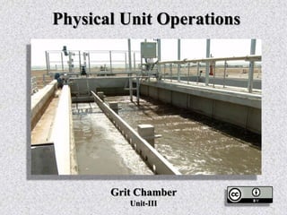
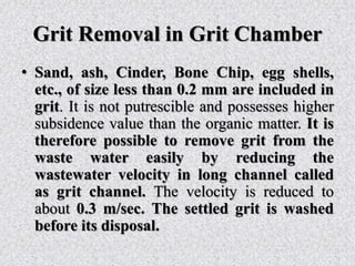
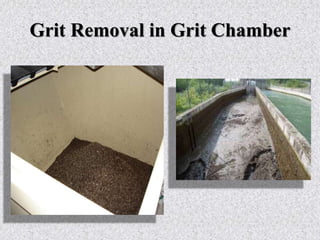
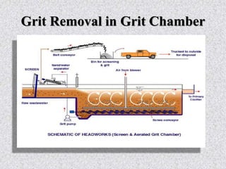
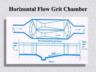
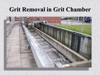
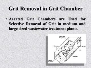
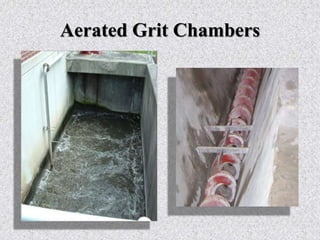
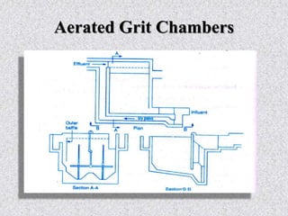

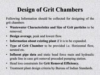
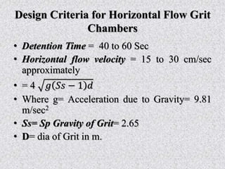
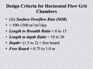
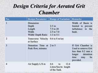
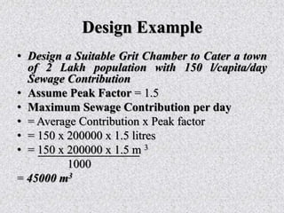
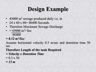
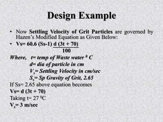
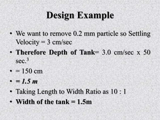
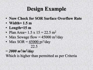
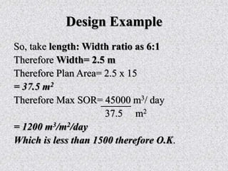
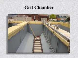

This document provides information about grit removal in wastewater treatment. It discusses that grit such as sand and eggshells can be easily removed from wastewater by reducing the velocity in a grit channel. Grit chambers are used to remove these particles to prevent damage to equipment and clogging. There are two main types of grit chambers - horizontal flow and aerated. The document provides design criteria for both types and works through an example design for a grit chamber for a town with a population of 200,000.


