1. Various essential accessories in sewerage systems are called sewer appurtenances. They include manholes, drop manholes, lamp holes, street inlets, catch basins, flushing devices, grease/oil/sand traps, inverted siphons, sewer outlets, and ventilating shafts.
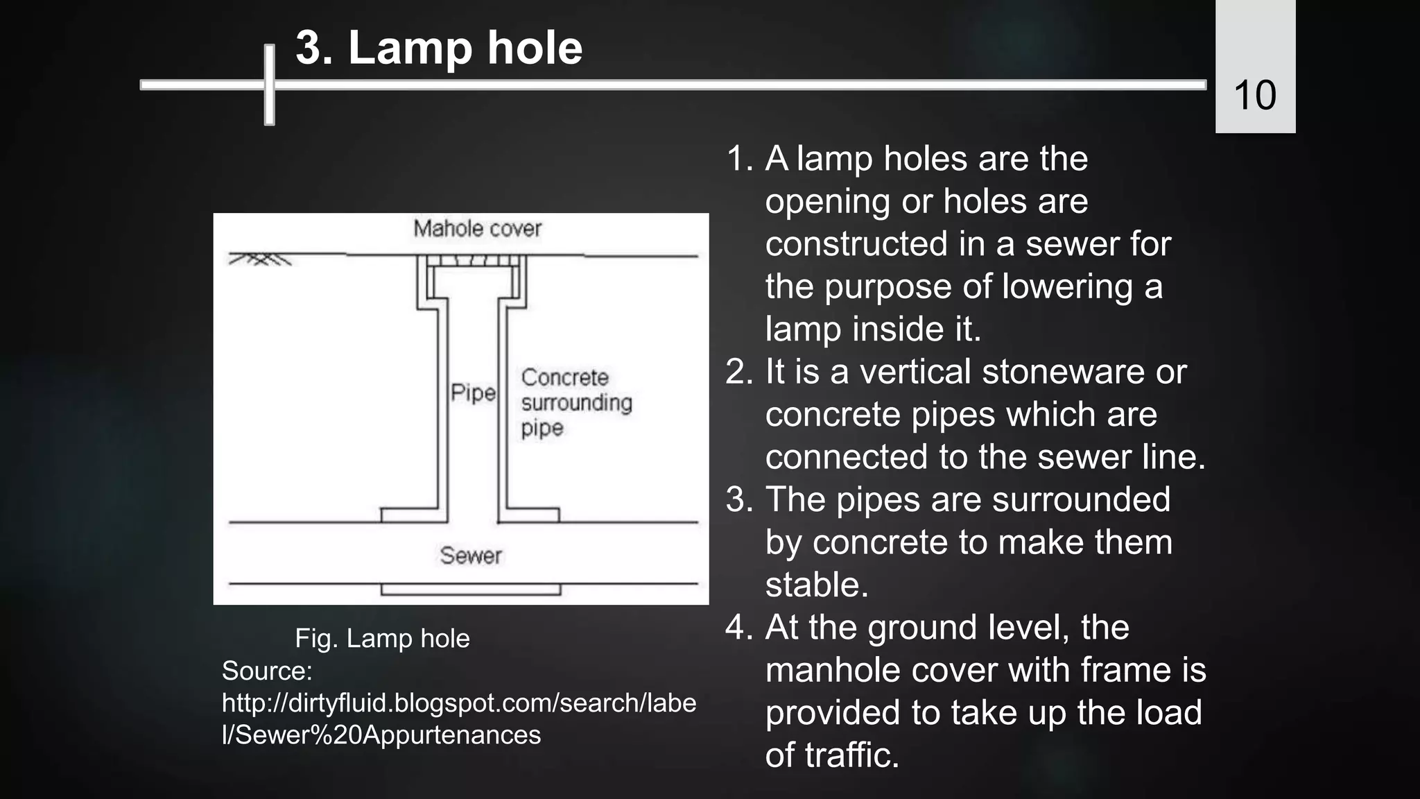
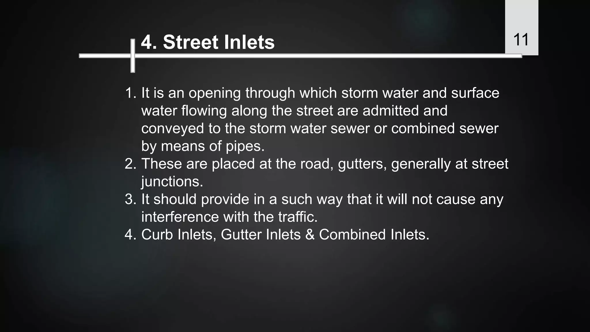
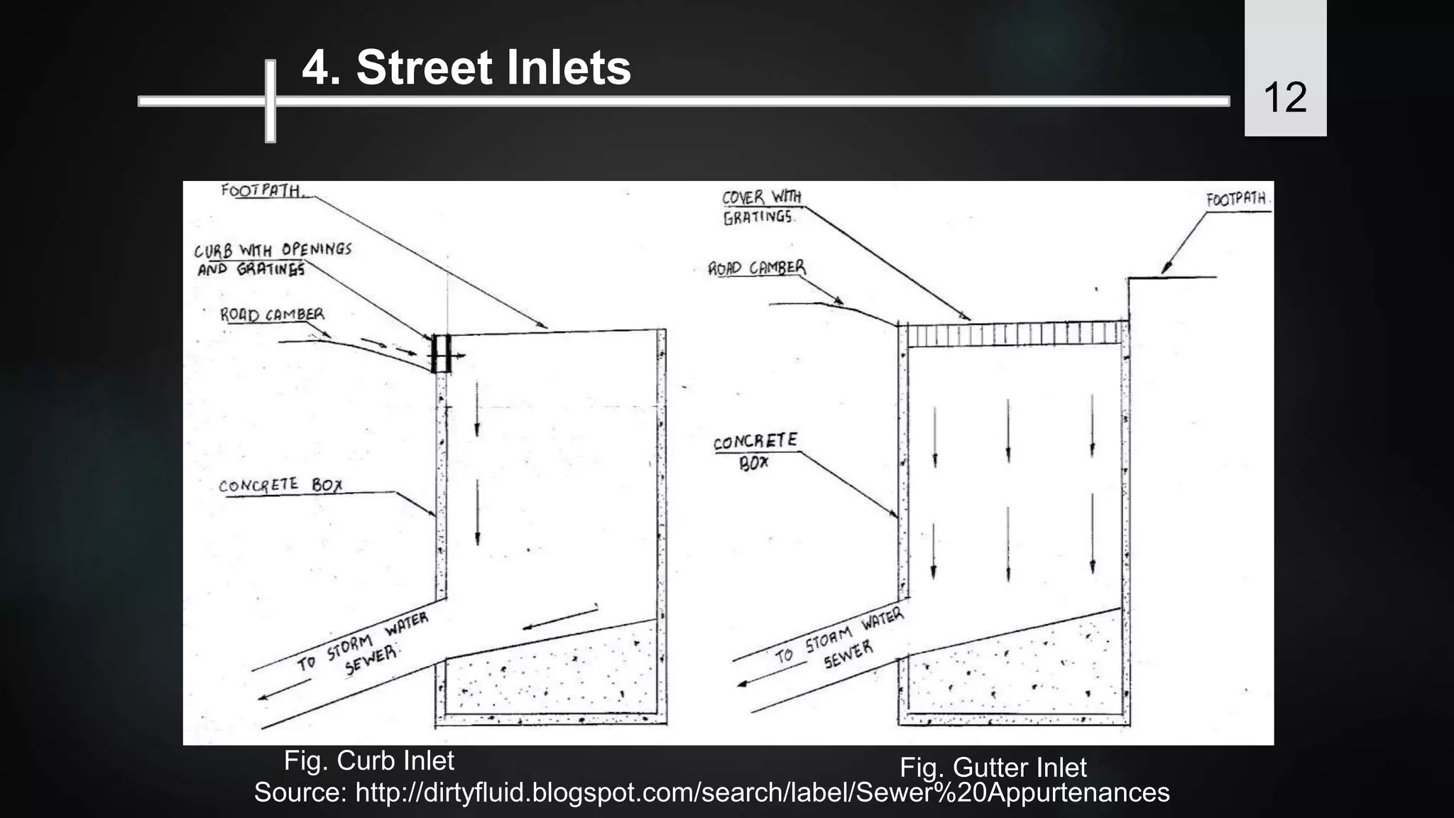
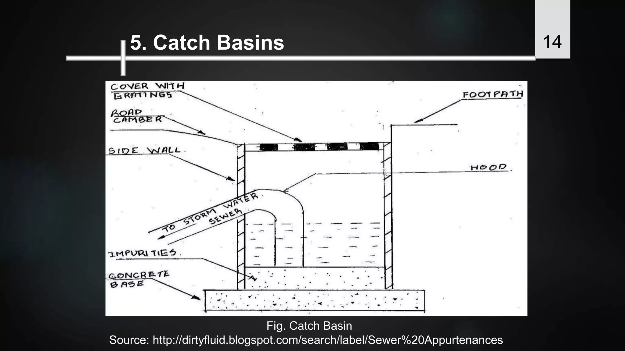
2. Manholes allow inspection, cleaning, repair and flow measurement of sewers. Drop manholes are used when the connection cannot be arranged within 60cm of the manhole invert. Lamp holes have openings for lowering lamps into sewers. Street inlets admit stormwater into sewers. Catch basins remove grit before sewage enters sewers.
3. Flushing devices use


![Sewer appurtenances [recovered]](https://cdn.slidesharecdn.com/ss_thumbnails/sewerappurtenancesrecovered-180318135220-thumbnail.jpg?width=640&height=640&fit=bounds)