Downloaded 734 times


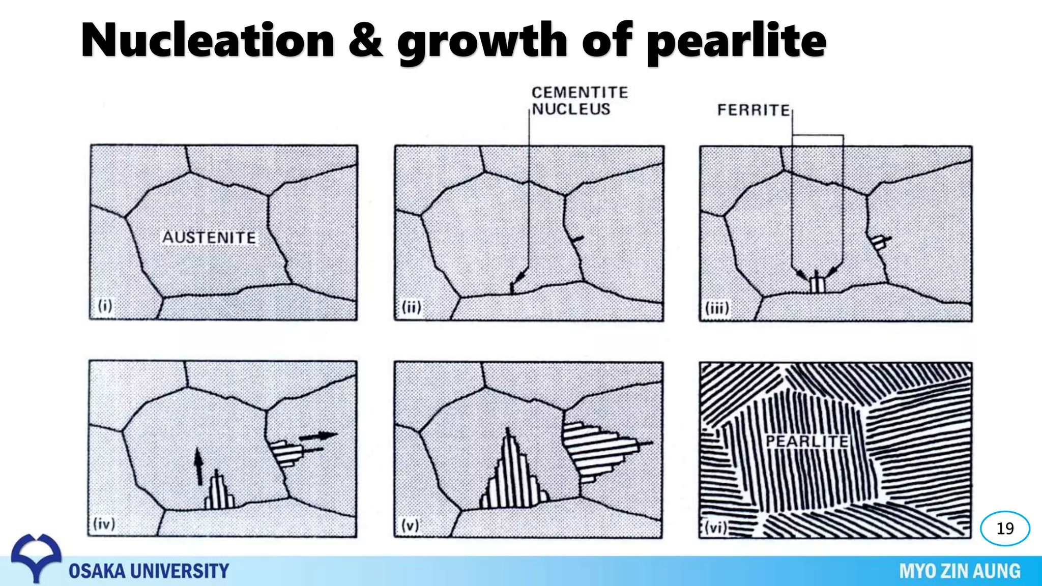


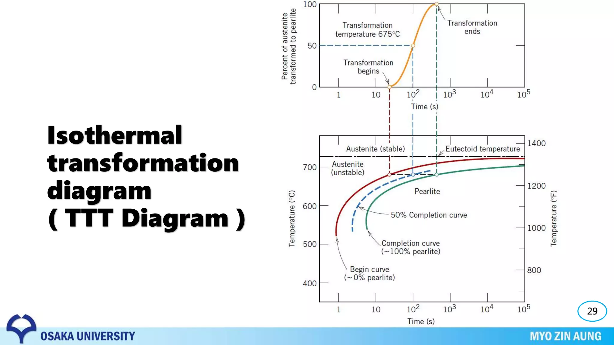

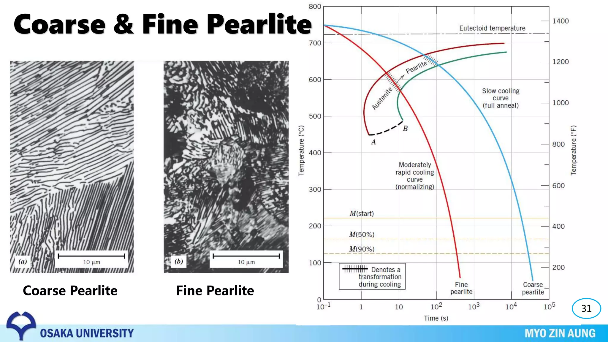
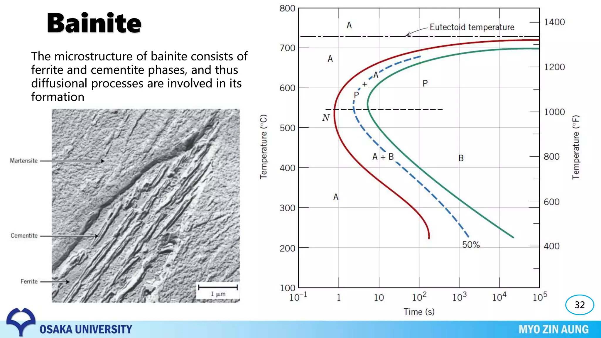


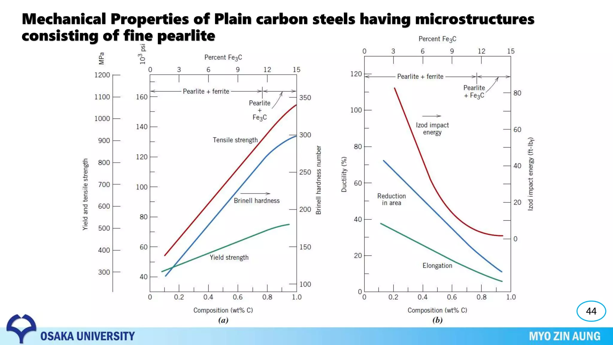


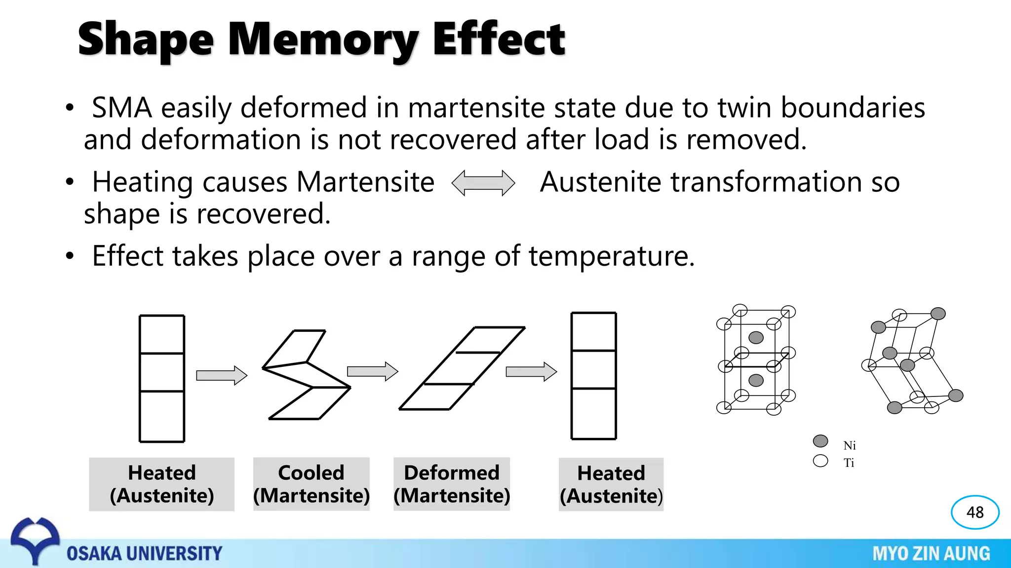


Phase transformations can occur in materials through changes in temperature, composition, or external pressure. These transformations involve changes in the crystal structure or phases of the material on an atomic scale. Three key phase transformations discussed in the document are the transformation of austenite to pearlite or bainite in steels through diffusion-dependent or diffusionless processes, the transformation of austenite to martensite through rapid cooling, and shape memory effects seen in alloys like nickel-titanium. The properties of the material, like its strength and hardness, depend on the microstructure resulting from the phase transformation, such as pearlite, bainite, or martensite, which can be controlled through heat