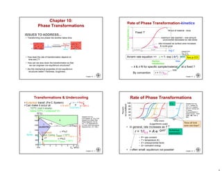
1. Chapter 10 - 1
ISSUES TO ADDRESS...
• Transforming one phase into another takes time.
• How does the rate of transformation depend on
time and T?
• How can we slow down the transformation so that
we can engineer non-equilibrium structures?
• Are the mechanical properties of non-equilibrium
structures better? Hardness, toughness ..
Fe
(Austenite)
Eutectoid
transformation
C FCC
Fe3C
(cementite)
(ferrite)
+
(BC
C)
Chapter 10:
Phase Transformations
Chapter 10 - 2
Rate of Phase Transformation-kinetics
Avrami rate equation => y = 1- exp (-ktn)
– k & n fit for specific sample/material at a fixed ?
All out of material - done
log t
Fractiontransformed,y
Fixed T
fraction
transformed
time
0.5
By convention r = 1 / t0.5
Adapted from
Fig. 10.10,
Callister 7e.
maximum rate reached – now amount
unconverted decreases so rate slows
t0.5
rate increases as surface area increases
& nuclei grow
rate
See p-323
Chapter 10 - 3
Transformations & Undercooling
• Can make it occur at:
...727ºC (cool it slowly)
...below 727ºC (“undercool” it!)
• Eutectoid transf. (Fe-C System): + Fe3C
0.76 wt% C
0.022 wt% C
6.7 wt% C
Fe3C(cementite)
1600
1400
1200
1000
800
600
400
0 1 2 3 4 5 6 6.7
L
(austenite)
+L
+Fe3C
+Fe3C
L+Fe3C
(Fe) Co, wt%C
1148°C
T(°C)
ferrite
727°C
Eutectoid:
Equil. Cooling: Ttransf. = 727ºC
T
Undercooling by Ttransf. < 727C
0.76
0.022
Adapted from Fig.
9.24,Callister 7e. (Fig. 9.24
adapted from Binary Alloy
Phase Diagrams, 2nd ed.,
Vol. 1, T.B. Massalski (Ed.-
in-Chief), ASM International,
Materials Park, OH, 1990.)
Chapter 10 - 4
Rate of Phase Transformations
• In general, rate increases as T
r = 1/t0.5 = A e -Q/RT
– R = gas constant
– T = temperature (K)
– A = preexponential factor
– Q = activation energy
Arrhenius
expression
• r often small: equilibrium not possible!
Adapted from Fig.
10.11, Callister 7e.
(Fig. 10.11 adapted
from B.F. Decker and
D. Harker,
"Recrystallization in
Rolled Copper", Trans
AIME, 188, 1950, p.
888.)
135C 119C 113C 102C 88C 43C
1 10 102 104
Cu
These all look
same rate/slope?
2. Chapter 10 - 5
Review Phase X-formation
• Nucleation
• Undercooling
• Superheating
• T0.5=?
102C
1 10 102 104
?C
?C
Which one for higher
temperature?
Similar to
nucleation
Chapter 10 - 6
Eutectoid Transformation Rate
Course pearlite formed at higher T - relatively softer
Fine pearlite formed at low T - relatively harder
Diffusive flow
of C needed
• Growth of pearlite from austenite:
Adapted from
Fig. 9.15,
Callister 7e.
pearlite
growth
direction
Austenite ()
grain
boundary
cementite (Fe3C)
Ferrite ()
• Recrystallization
rate increases
with T. Adapted from
Fig. 10.12,
Callister 7e.
675°C
(T smaller)
0
50
y(%pearlite)
600°C
(T larger)
650°C
100
High C%
Low C%
Uniform
C%
Chapter 10 - 7
• Reaction/transformation rate is a result of
nucleation and growth of crystals.
• Examples:
Adapted from
Fig. 10.10, Callister 7e.
Nucleation and Growth
% Pearlite
0
50
100
Nucleation
regime
Growth
regime
log(time)t0.5
Nucleation rate increases with T
Growth rate increases with T
T just below TE
Nucleation rate low
Growth rate high
pearlite
colony
T moderately below TE
Nucleation rate med
Growth rate med.
Nucleation rate high
T way below TE
Growth rate low
Chapter 10 - 8
Adapted from Fig. 10.13,Callister 7e.
(Fig. 10.13 adapted from H. Boyer (Ed.)
Atlas of Isothermal Transformation and
Cooling Transformation Diagrams,
American Society for Metals, 1977, p.
369.)
Isothermal Transformation Diagrams
How is it created..
• Fe-C system, Co = 0.76 wt% C
• Transformation at T = 675°C.
100
50
0
1 102 104
T = 675°C
y,
%transformed
time (s)
400
500
600
700
1 10 102 103 104 105
Austenite (stable)
TE (727C)Austenite
(unstable)
Pearlite
T(°C)
time (s)
isothermal transformation at 675°C
3. Chapter 10 - 9
• Eutectoid composition, Co = 0.76 wt% C
• Begin at T > 727°C
• Rapidly cool to 625°C and hold isothermally.
Adapted from Fig.
10.14,Callister 7e.
(Fig. 10.14 adapted from
H. Boyer (Ed.) Atlas of
Isothermal Transformation
and Cooling
Transformation Diagrams,
American Society for
Metals, 1997, p. 28.)
Effect of Cooling History in Fe-C System
400
500
600
700
Austenite (stable)
TE (727C)
Austenite
(unstable)
Pearlite
T(°C)
1 10 102 103 104 105
time (s)
Chapter 10 -10
Non-Equilibrium Transformation
Products: Fe-C
• Bainite:
-- lathes (strips) with long
rods of Fe3C
--diffusion controlled.
• Isothermal Transf. Diagram
Adapted from Fig. 10.18, Callister 7e.
(Fig. 10.18 adapted from H. Boyer (Ed.) Atlas of Isothermal Transformation and Cooling
Transformation Diagrams, American Society for Metals, 1997, p. 28.)
(Adapted from Fig. 10.17, Callister, 7e. (Fig.
10.17 from Metals Handbook, 8th ed.,
Vol. 8, Metallography, Structures, and Phase
Diagrams, American Society for Metals,
Materials Park, OH, 1973.)
Fe3C
(cementite)
5 m
(ferrite)
10 103
105
time (s)
10-1
400
600
800
T(°C)
Austenite (stable)
200
P
B
TE
pearlite/bainite boundary
A
A
100% bainite
100% pearlite
Chapter 10 -11
Transformations with
Proeutectoid Materials
Hypereutectoid composition – proeutectoid cementite
CO = 1.13 wt% C
TE (727°C)
T(°C)
time (s)
A
A
A
+
C
P
1 10 102 103 104
500
700
900
600
800
A
+
P
Adapted from Fig. 10.16,
Callister 7e.
Adapted from Fig. 9.24,
Callister 7e.
Fe3C(cementite)
1600
1400
1200
1000
800
600
400
0 1 2 3 4 5 6 6.7
L
(austenite)
+L
+Fe3C
+Fe3C
L+Fe3C
(Fe)
Co, wt%C
T(°C)
727°C
T
0.76
0.022
1.13
Chapter 10 -12
• Spheroidite:
-- grains with spherical Fe3C
--diffusion dependent.
--heat bainite or pearlite for long times
--reduces interfacial area (driving force)
Spheroidite: Fe-C System
(Adapted from Fig. 10.19, Callister, 7e.
(Fig. 10.19 copyright United States
Steel Corporation, 1971.)
60 m
(ferrite)
(cementite)
Fe3C
4. Chapter 10 -13
• Martensite:
--(FCC) to Martensite (BCT)
Adapted from
Fig. 10.22,
Callister 7e.
(Adapted from Fig. 10.21, Callister, 7e.
(Fig. 10.21 courtesy United States
Steel Corporation.)
• Isothermal Transf. Diagram
• to M transformation..
-- is rapid!
-- % transf. depends on T only.
(Adapted from Fig.
10.20, Callister, 7e.
Martensite: Fe-C System
Martensite needles
Austenite
60m
10 103
105
time (s)10-1
400
600
800
T(°C)
Austenite (stable)
200
P
B
TEA
A
M + A
M + A
M + A
0%
50%
90%
x
x x
x
x
x
potential
C atom sites
Fe atom
sites
(involves single atom jumps)
Chapter 10 -14
(FCC) (BCC) + Fe3C
Martensite Formation
slow cooling
tempering
quench
M (BCT)
M = martensite is body centered tetragonal (BCT)
Diffusionless transformation BCT if C > 0.15 wt%
BCT few slip planes hard, brittle
Chapter 10 -15
Phase Transformations of Alloys
Effect of adding other elements
Change transition temp.
Cr, Ni, Mo, Si, Mn
retard + Fe3C
transformation
Adapted from Fig. 10.23, Callister 7e.
e.g. 4340 steel
C .38-.43
Mn .6 - .8%
P .035% Max
S .04% max
Si .15 - .3%
Cr .7 - .9
Ni 1.65-2.0
Mo .2 -.3
Oil Q. Tempered 630C
Chapter 10 -16
Adapted from
Fig. 10.25,
Callister 7e.
Cooling Curve
Continuous cooling
plot temp vs. time
•It takes time to
transform.
•It may not be able
to keep up with
cooling rate
•Transformation
diagram changes
somewhat
5. Chapter 10 -17
Dynamic Phase Transformations
On the isothermal transformation diagram for
0.45 wt% C Fe-C alloy, sketch and label the
time-temperature paths to produce the
following microstructures:
a) 42% proeutectoid ferrite and 58% coarse
pearlite
b) 50% fine pearlite and 50% bainite
c) 100% martensite
d) 50% martensite and 50% austenite
Chapter 10 -18
A + B
A + P
A +
A
B
P
A
50%
0
200
400
600
800
0.1 10 103 105
time (s)
M (start)
M (50%)
M (90%)
Example Problem for Co = 0.45 wt%
a) 42% proeutectoid ferrite and 58% coarse pearlite
first make ferrite
then pearlite
course pearlite
higher T
Adapted from
Fig. 10.29,
Callister 5e.
T (°C)
Chapter 10 -19
b) 50% fine pearlite and 50% bainite
first make pearlite
then bainite
fine pearlite
lower T
T (°C)
A + B
A + P
A +
A
B
P
A
50%
0
200
400
600
800
0.1 10 103 105
time (s)
M (start)
M (50%)
M (90%)
Example Problem for Co = 0.45 wt%
Adapted from
Fig. 10.29,
Callister 5e.
Chapter 10 -20
A + B
A + P
A +
A
B
P
A
50%
0
200
400
600
800
0.1 10 103 105
time (s)
M (start)
M (50%)
M (90%)
Example Problem for Co = 0.45 wt%
c) 100 % martensite – quench = rapid cool
d) 50 % martensite
and 50 %
austenite
d)
c)Adapted from
Fig. 10.29,
Callister 5e.
T (°C)
6. Chapter 10 -21
Tempering Martensite
• reduces brittleness of martensite,
• reduces internal stress caused by quenching.
Adapted from
Fig. 10.33,
Callister 7e.
(Fig. 10.33
copyright by
United States
Steel
Corporation,
1971.)
• decreases TS, YS but increases %RA
• produces extremely small Fe3C particles surrounded by
Adapted from
Fig. 10.34,
Callister 7e.
(Fig. 10.34
adapted from
Fig. furnished
courtesy of
Republic Steel
Corporation.)
9m
YS(MPa)
TS(MPa)
800
1000
1200
1400
1600
1800
30
40
50
60
200 400 600
Tempering T(°C)
%RA
TS
YS
%RA
Chapter 10 -22
Summary: Processing Options
Adapted from
Fig. 10.36,
Callister 7e.
Austenite ()
Bainite
( + Fe3C plates/needles)
Pearlite
( + Fe3C layers + a
proeutectoid phase)
Martensite
(BCT phase
diffusionless
transformation)
Tempered
Martensite
( + very fine
Fe3C particles)
slow
cool
moderate
cool
rapid
quench
reheat
Strength
Ductility
Martensite
T Martensite
bainite
fine pearlite
coarse pearlite
spheroidite
General Trends