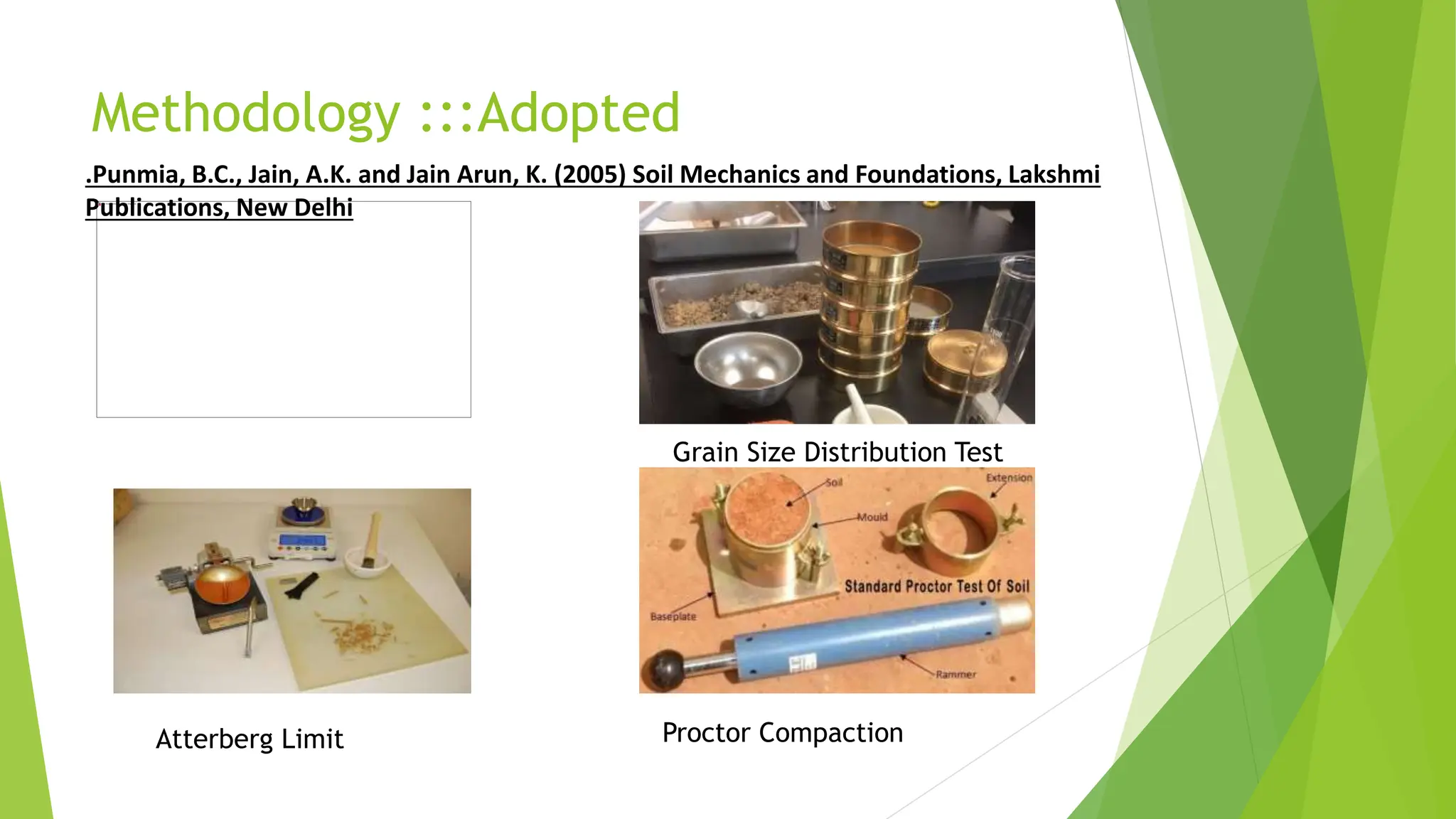
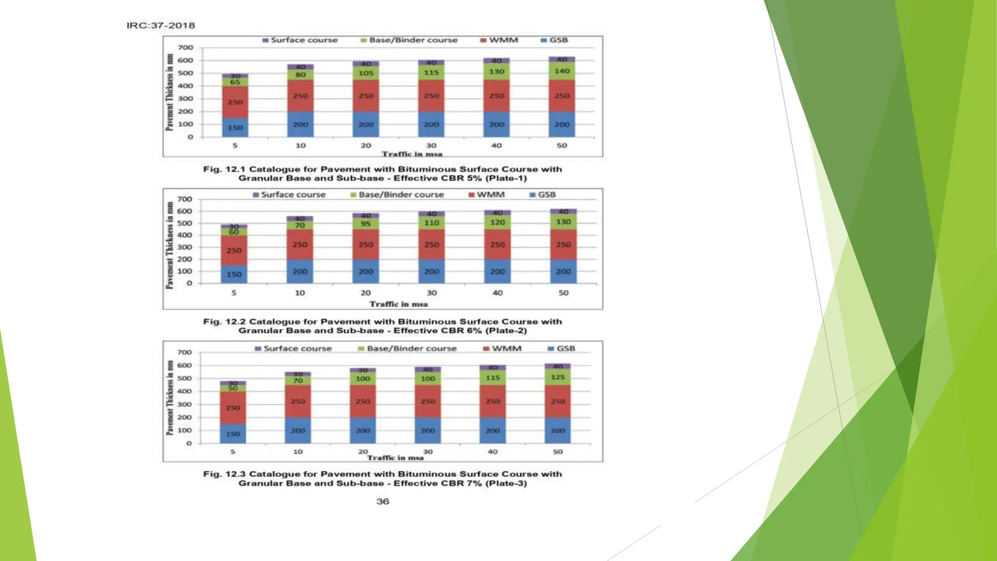
A Detailed study on CBR Method for flexible
Pavement Design
Guided By: Ms. Shibani Hota
Submitted by :Binayalal Patra
University Registration No:2207298002
Branch : MTech
Stream: CTM
Year :2022-24
Problem Statement :::
 Sufficient thickness of base and surface must be placed over the
subgrade to prevent failure within the subgrade.
 The shearing strengths of the layers of flexible pavement close to the
loaded area, i.e., of the base course and bituminous surface, must be
high enough that failure along shear surfaces entirely within the base
and surface will not occur.
 The possibility of failure of any one layer by squeezing out laterally
under the applied load must be studied, e.g., a poorly designed
bituminous surface may be squeezed out between the tires of traffic
and the base course.
Reason / Inspiration for selecting the
Topic :::
 Designing pavement by CBR method gives total thickness requirement of the
pavement above a subgrade. On the basis of estimation of traffic load &
bearing capacity of subgrade will lead to cost effective designing of roads.
Produce least noise from moving vehicles. CBR is a penetration test which is
used to evaluate the subgrade strength primarily of roads, pavements and
foundations
 Subgrade strength plays an important role in the design and construction of
pavement. California bearing ratio (CBR) test is used to measure the strength
of subgrade and most of the highway agencies design the pavement section
using CBR value of the subgrade. This method is based on design charts that are
prepared by the California state highway department after performing
extensive CBR tests on existing highways. The basis of the design chart is that a
material with a given CBR required a certain thickness of pavement layer as
cover for a given vehicular load.
Review of Literature:: ( recent literature from year
2014-23 may be choosen for review.)
 1. IRC: 37: 2012, “Guidelines for Design of Flexible pavement”,
second revision.
 2. IRC: 37: 2001, “Tentative guidelines for Design of Flexible
pavement”
 3. IRC 37-2018 “Code of guideline for the design of flexible
pavement for highway”, Indian Road Congress, New Delhi 2018
 4. Khan, I.H. (1998) A Textbook of Geotechnical Engineering,
Pentice Hall of India Private Limited, New Delhi
 5. Punmia, B.C., Jain, A.K. and Jain Arun, K. (2005) Soil
Mechanics and Foundations, Lakshmi Publications, New Delhi
Methodology :::Adopted
.Punmia, B.C., Jain, A.K. and Jain Arun, K. (2005) Soil Mechanics and Foundations, Lakshmi
Publications, New Delhi
Grain Size Distribution Test
Atterberg Limit Proctor Compaction
Methodology :::Adopted
The California Bearing Ratio (CBR) test is an empirical method of design of
flexible pavement design. It was developed by the California Department of
Transportation before World War II. The basic site test is performed by measuring
the pressure required to penetrate soil or aggregate with a plunger of standard
area.
CBR is the ratio expressed in percentage of force per unit area required to
penetrate a soil mass with a standard circular plunger of 50 mm diameter at the
rate of 1.25 mm/min to that required for corresponding penetration in a
standard material. The ratio is usually determined for penetration of 2.5 and 5
mm .
CBR value varies from 0 to 100%. More CBR indicates the stronger soil. Ifdensity
is less, CBR is less. The CBR is expressed as percentage of penetration
resistanceof a given pavement material to that of a standard value of
penetration resistance obtained for a crusher stone aggregate available in
California.
 Three samples of soils had been collected in the location of the site (work).
 The different types of tests conducted on the samples are (a) Index
Properties and (b) Engineering Properties.
 Index Properties of Soil should be Determined by the various test like Liquid
limit ,Plastic Limit ,Specific Gravity and Sieve Analysis of Soil.
 Engineering Properties of Soil should be Determined by Standard or Modified
Proctor Test.
 Final CBR test is a penetration test developed by the California division of
highways, as a method evaluating the stability of soil sub-grade and other
flexible highway materials. The test results have been correlated with the
pavement thickness requirements for highways and airfields. The CBR test
may be conducted in the laboratory on a prepared specimen in a mould or in-
situ in the field.
Works to be conducted::::
CBR TEST PROCEDURE:
 1. About 5kg of oven dried soil sample is taken and is mixed with optimum
moisture content. The soil is then compacted either by IS light compaction (3
layers, 55 blows, each by 2.6 kg hammer) or IS heavy compaction (5 layers, 55
blows, each by 4.89 kg hammer).
 2. The mould with the base plate is placed under the penetration plunger of
the loading machine and a surcharge weight of 2.5 kg is applied
 3. The dial gauge for measuring the penetration values of the plunger is fitted
in position. The dial gauge of the proving ring and the penetration dial gauge
are set. The load readings are recorded at penetration readings of 0.0, 0.5,
1.0, 1.5, 2.0, 2.5, 3.0, 3.5, 4.0, 4.5, 5.0, 5.5, 6.0, 6.5, 7.0 etc.,
 4. The proving ring calibration factor is noted. The load penetration curve is
the plotted. The unit load values corresponding to 2.5mm and 5.0mm
penetration values are found from the graph.
 5. This load is expressed as a percentage of standard load values at the
respective deformation level to obtain the CBR value. The CBR for 2.5mm
penetration is taken .
 2. CBR value is calculated by the formula,
 CBR = [(Load sustained by specimen at defined penetration level)/(Load
sustained by sustained crushed stone at same penetration level)]*100
 3. The dial gauge for measuring the penetration values of the plunger is fitted
in position. The dial gauge of the proving ring and the penetration dial gauge
are set. The load readings are recorded at penetration readings of 0.0, 0.5,
1.0, 1.5, 2.0, 2.5, 3.0, 3.5, 4.0, 4.5, 5.0, 5.5, 6.0, 6.5, 7.0 etc.
DESIGN:
 From Clause3.3.6 fo IRC: 37.2018 stipulates the design traffic in term of
cumulative number of standard axels to be carried during the design life of
the road. This is computed using the following eduation.
 N = 365 x[( I + r )n x A x D x F
r
 Where N = Cumulative No. of standard Axles to be carried for in the design
in terms of MSA.
A = Initial traffic in the year of completion of construction interims of no. of
Commercial vehicle per day.
D = Lane distribution factor , F = Vehicle damaged factor.
n = Design life in year 15 years,R = Annual growth rate of commercial vehicle.
 After Determination of MSA Value , the Crust Thickness can be determined
from the above IRC Figure .
 It has been concluded that the thickness of crust varies with the change in
the value of C.B.R. With higher value of C.B.R. the crust thickness is less and
vice versa. r
 Due to the saving in crust, less quantity of material will be applicable so that,
huge amount of money can be saved
 Further this research work can be carried with the different soacking
conditions of soil with respect to time, and improving the C.B.R values with
the stabilization process with the different materials.
CONCLUSION:
Project completion strategy:::
Reference::
 Highway Engineering” by S.K.Khanna and C.E.G.Justo
 Highway Engineering” by T.D.Ahuja
 Soil mechanics and foundation engineering” by K.R.Arora
 Surveying” by B.C.Punmia
 Surveying” by K.R.Arora
 IRC 37-2018” : Guidelines for the design of flexible pavements.
 Estimation and costing in civil engineering” by B.N.Dutta

CBR Method of Design a Flexible pavement

  • 1.
    A Detailed studyon CBR Method for flexible Pavement Design Guided By: Ms. Shibani Hota Submitted by :Binayalal Patra University Registration No:2207298002 Branch : MTech Stream: CTM Year :2022-24
  • 2.
    Problem Statement ::: Sufficient thickness of base and surface must be placed over the subgrade to prevent failure within the subgrade.  The shearing strengths of the layers of flexible pavement close to the loaded area, i.e., of the base course and bituminous surface, must be high enough that failure along shear surfaces entirely within the base and surface will not occur.  The possibility of failure of any one layer by squeezing out laterally under the applied load must be studied, e.g., a poorly designed bituminous surface may be squeezed out between the tires of traffic and the base course.
  • 3.
    Reason / Inspirationfor selecting the Topic :::  Designing pavement by CBR method gives total thickness requirement of the pavement above a subgrade. On the basis of estimation of traffic load & bearing capacity of subgrade will lead to cost effective designing of roads. Produce least noise from moving vehicles. CBR is a penetration test which is used to evaluate the subgrade strength primarily of roads, pavements and foundations  Subgrade strength plays an important role in the design and construction of pavement. California bearing ratio (CBR) test is used to measure the strength of subgrade and most of the highway agencies design the pavement section using CBR value of the subgrade. This method is based on design charts that are prepared by the California state highway department after performing extensive CBR tests on existing highways. The basis of the design chart is that a material with a given CBR required a certain thickness of pavement layer as cover for a given vehicular load.
  • 4.
    Review of Literature::( recent literature from year 2014-23 may be choosen for review.)  1. IRC: 37: 2012, “Guidelines for Design of Flexible pavement”, second revision.  2. IRC: 37: 2001, “Tentative guidelines for Design of Flexible pavement”  3. IRC 37-2018 “Code of guideline for the design of flexible pavement for highway”, Indian Road Congress, New Delhi 2018  4. Khan, I.H. (1998) A Textbook of Geotechnical Engineering, Pentice Hall of India Private Limited, New Delhi  5. Punmia, B.C., Jain, A.K. and Jain Arun, K. (2005) Soil Mechanics and Foundations, Lakshmi Publications, New Delhi
  • 5.
    Methodology :::Adopted .Punmia, B.C.,Jain, A.K. and Jain Arun, K. (2005) Soil Mechanics and Foundations, Lakshmi Publications, New Delhi Grain Size Distribution Test Atterberg Limit Proctor Compaction
  • 6.
    Methodology :::Adopted The CaliforniaBearing Ratio (CBR) test is an empirical method of design of flexible pavement design. It was developed by the California Department of Transportation before World War II. The basic site test is performed by measuring the pressure required to penetrate soil or aggregate with a plunger of standard area. CBR is the ratio expressed in percentage of force per unit area required to penetrate a soil mass with a standard circular plunger of 50 mm diameter at the rate of 1.25 mm/min to that required for corresponding penetration in a standard material. The ratio is usually determined for penetration of 2.5 and 5 mm . CBR value varies from 0 to 100%. More CBR indicates the stronger soil. Ifdensity is less, CBR is less. The CBR is expressed as percentage of penetration resistanceof a given pavement material to that of a standard value of penetration resistance obtained for a crusher stone aggregate available in California.
  • 7.
     Three samplesof soils had been collected in the location of the site (work).  The different types of tests conducted on the samples are (a) Index Properties and (b) Engineering Properties.  Index Properties of Soil should be Determined by the various test like Liquid limit ,Plastic Limit ,Specific Gravity and Sieve Analysis of Soil.  Engineering Properties of Soil should be Determined by Standard or Modified Proctor Test.  Final CBR test is a penetration test developed by the California division of highways, as a method evaluating the stability of soil sub-grade and other flexible highway materials. The test results have been correlated with the pavement thickness requirements for highways and airfields. The CBR test may be conducted in the laboratory on a prepared specimen in a mould or in- situ in the field. Works to be conducted::::
  • 8.
    CBR TEST PROCEDURE: 1. About 5kg of oven dried soil sample is taken and is mixed with optimum moisture content. The soil is then compacted either by IS light compaction (3 layers, 55 blows, each by 2.6 kg hammer) or IS heavy compaction (5 layers, 55 blows, each by 4.89 kg hammer).  2. The mould with the base plate is placed under the penetration plunger of the loading machine and a surcharge weight of 2.5 kg is applied  3. The dial gauge for measuring the penetration values of the plunger is fitted in position. The dial gauge of the proving ring and the penetration dial gauge are set. The load readings are recorded at penetration readings of 0.0, 0.5, 1.0, 1.5, 2.0, 2.5, 3.0, 3.5, 4.0, 4.5, 5.0, 5.5, 6.0, 6.5, 7.0 etc.,  4. The proving ring calibration factor is noted. The load penetration curve is the plotted. The unit load values corresponding to 2.5mm and 5.0mm penetration values are found from the graph.
  • 9.
     5. Thisload is expressed as a percentage of standard load values at the respective deformation level to obtain the CBR value. The CBR for 2.5mm penetration is taken .  2. CBR value is calculated by the formula,  CBR = [(Load sustained by specimen at defined penetration level)/(Load sustained by sustained crushed stone at same penetration level)]*100  3. The dial gauge for measuring the penetration values of the plunger is fitted in position. The dial gauge of the proving ring and the penetration dial gauge are set. The load readings are recorded at penetration readings of 0.0, 0.5, 1.0, 1.5, 2.0, 2.5, 3.0, 3.5, 4.0, 4.5, 5.0, 5.5, 6.0, 6.5, 7.0 etc.
  • 10.
    DESIGN:  From Clause3.3.6fo IRC: 37.2018 stipulates the design traffic in term of cumulative number of standard axels to be carried during the design life of the road. This is computed using the following eduation.  N = 365 x[( I + r )n x A x D x F r  Where N = Cumulative No. of standard Axles to be carried for in the design in terms of MSA. A = Initial traffic in the year of completion of construction interims of no. of Commercial vehicle per day. D = Lane distribution factor , F = Vehicle damaged factor. n = Design life in year 15 years,R = Annual growth rate of commercial vehicle.
  • 12.
     After Determinationof MSA Value , the Crust Thickness can be determined from the above IRC Figure .  It has been concluded that the thickness of crust varies with the change in the value of C.B.R. With higher value of C.B.R. the crust thickness is less and vice versa. r  Due to the saving in crust, less quantity of material will be applicable so that, huge amount of money can be saved  Further this research work can be carried with the different soacking conditions of soil with respect to time, and improving the C.B.R values with the stabilization process with the different materials. CONCLUSION:
  • 13.
  • 14.
    Reference::  Highway Engineering”by S.K.Khanna and C.E.G.Justo  Highway Engineering” by T.D.Ahuja  Soil mechanics and foundation engineering” by K.R.Arora  Surveying” by B.C.Punmia  Surveying” by K.R.Arora  IRC 37-2018” : Guidelines for the design of flexible pavements.  Estimation and costing in civil engineering” by B.N.Dutta