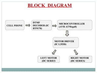
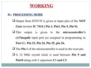
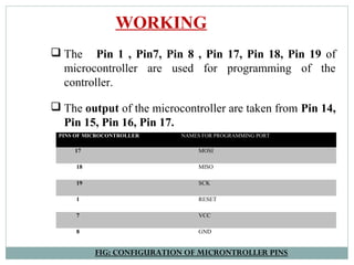
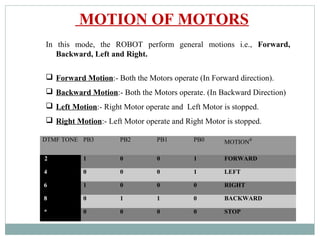
MOBILE CONTROLLED ROBOT
HIMANSHU RAMCHANDANI
MANGAL DAS
MANISH JAISWAL
MOHIT KATIYAR
Final Year, ECE
CONCEPT OF PROJECT
SPECIFICATIONS
 Standard features are used.
 Cell phones used for the connection should be specified
models like Nokia 1100, Nokia 1600.
 Working communication through a hands-free jack.
 Connection between cell phones are manually activated.
 System is an open-loop system.
TECHNOLOGY
DUAL-TONE MULTI-FREQUENCY (DTMF)
Dual Tone Multi Frequency (DTMF) tone is the
signal to the network center that is generated when
any key of telephone is pressed.
With DTMF, each key pressed on phone, generates
two tones of specific frequencies.
One tone is generated from a high-frequency group
of tones and the other from a low frequency group.
TECHNOLOGY
The row in which the key appears determine the low
frequency, and column determine the high frequencies.
 For example, pressing the ‘1’ key will result in a
sound composed of both a 697 Hz and a 1209 Hz tone.
DUAL-TONE MULTI-FREQUENCY (DTMF)
FIG: FREQUENCY TABLE
 HT9170 series IC’s are DTMF
tone receivers.
 They are integrated with Digital
Decoder.
 Detects and decode all the 16
DTMF tone pairs into 4 bit code.
DTMF DECODER
FIG: PIN DIAGRAM
FIG:CIRCUIT CONNECTION
DTMF DECODER
 Built-in Dial tone rejection
circuit eliminates the need of
pre- filtering.
 When input signals are
recognized to be effective,
DV becomes high, and the
correct tone code (DTMF)
digit is transferred.
 The low group filter filters
low group frequency signal
output whereas the high
group filter filters high group
frequency signal output.
BLOCK DIAGRAM
CELL PHONE
MICROCONTROLLER
(AVR ATMega8)
MOTOR DRIVER
(IC L293D)
DTMF
DECODER (IC
HT9170)
LEFT MOTOR
(DC SERIES
RIGHT MOTOR
(DC SERIES)
FLOWCHART
CIRCUIT DIAGRAM
WORKING
A.) INPUT MODE
 Input is given from hands-free connected to mobile
(stacked on Robot).
 Input is a DTMF Tone sent through a mobile far distant
from Robot.
 HT9170 series decoder is used at input.
 Detect and decode all the 16 DTMF tones pairs into a 4-
bit code output .
 4 bit binary code bit pattern is generated as D0,.D1,D2,D3
(Pin 11, Pin 12, Pin 13, Pin 14 of HT9170).
WORKING
DTMF
TONE
PC6 PC5 PC4 PC3 PC2 PC1 PC0
2 1 --- --- 1 1 0 1
4 1 --- --- 1 0 1 1
6 1 --- --- 1 0 0 1
8 1 --- --- 0 1 1 1
* 1 --- --- 0 0 1 1
FIG: INPUT TABLE FOR DTMF TONES
WORKING
B.) PROCESSING MODE
 Output from HT9170 is given at input pins of the NOT
Gate inverter IC 7414 ( Pin 1, Pin3, Pin 5, Pin 9).
 This output is given to the microcontroller’s
(ATmega8) input port (as assigned in programming as
Port C). Pin 23, Pin 24, Pin 25, pin 26.
 The Pin 1 of the microcontroller is used as the reset pin.
 A 12 MHz crystal clock is used between Pin 9 and
Pin10 along with 2 capacitors C1 and C2
PINS OF MICROCONTROLLER NAMES FOR PROGRAMMING PORT
17 MOSI
18 MISO
19 SCK
1 RESET
7 VCC
8 GND
 The Pin 1 , Pin7, Pin 8 , Pin 17, Pin 18, Pin 19 of
microcontroller are used for programming of the
controller.
 The output of the microcontroller are taken from Pin 14,
Pin 15, Pin 16, Pin 17.
WORKING
FIG: CONFIGURATION OF MICRONTROLLER PINS
WORKING
C.) OUTPUT MODE
 The Motor Driver IC L293d
is used for controlling the
motion of the motors .
 The Pin 2, Pin 7, Pin 10 and
Pin 15 are the input pins of
L293d IC
 Output pins are configured as
Pin 3, Pin 6, Pin 11, and Pin
14.
FIG: L293D IC
FIG: INTERNAL BLOCK DIAGRAM OF L293D
WORKING
In this mode, the ROBOT perform general motions i.e., Forward,
Backward, Left and Right.
 Forward Motion:- Both the Motors operate (In Forward direction).
 Backward Motion:- Both the Motors operate. (In Backward Direction)
 Left Motion:- Right Motor operate and Left Motor is stopped.
 Right Motion:- Left Motor operate and Right Motor is stopped.
DTMF TONE PB3 PB2 PB1 PB0 MOTION#
2 1 0 0 1 FORWARD
4 0 0 0 1 LEFT
6 1 0 0 0 RIGHT
8 0 1 1 0 BACKWARD
* 0 0 0 0 STOP
MOTION OF MOTORS
HARDWARE DESIGN
#define F_CPU 12000000UL // define CPU frequency for
delay function.
#include <avr/io.h> // includes input/output header file
#include <util/delay.h> // includes delay header file
DTMF=DTMF&0b0001111; //Mask high order 4 bits
if(DTMF==2) //if Key 2 of cell phone pressed
{
PORTB=0b00001001; // move straight
}
if(DTMF==4) // if Key 4 of cell phone pressed
{
PORTB=0b00000001; // turn left
}
PROGRAM CODE
if(DTMF==6) // if Key 6 of cell phone pressed
{
PORTB=0b00001000; // turn right
}
if(DTMF==8) // if Key 8 of cell phone pressed
{
PORTB=0b00000110; // move back
}
if(DTMF==11) // if Key * of cell phone pressed
{
PORTB=0b00000000; //stop
}
PROGRAM CODE
FURTHER ADVANCEMENTS
 LINE FOLLOWER, EDGE AVOIDER, SEARCHER,
AVOIDER.
 PC-CONTROLLED.
 FM-CONTROLLED.
APPLICATIONS
 VIDEO CALLING.
 CONTROLLING OF MULTIPLE ROBOTS.
 INTELLIGENCE.
 UAV’s.
 AUTONOMUS CAR.
 CONTROLLING HOME APPLIANCES.
THANK YOU

Presentation1

  • 1.
    MOBILE CONTROLLED ROBOT HIMANSHURAMCHANDANI MANGAL DAS MANISH JAISWAL MOHIT KATIYAR Final Year, ECE
  • 2.
  • 3.
    SPECIFICATIONS  Standard featuresare used.  Cell phones used for the connection should be specified models like Nokia 1100, Nokia 1600.  Working communication through a hands-free jack.  Connection between cell phones are manually activated.  System is an open-loop system.
  • 4.
    TECHNOLOGY DUAL-TONE MULTI-FREQUENCY (DTMF) DualTone Multi Frequency (DTMF) tone is the signal to the network center that is generated when any key of telephone is pressed. With DTMF, each key pressed on phone, generates two tones of specific frequencies. One tone is generated from a high-frequency group of tones and the other from a low frequency group.
  • 5.
    TECHNOLOGY The row inwhich the key appears determine the low frequency, and column determine the high frequencies.  For example, pressing the ‘1’ key will result in a sound composed of both a 697 Hz and a 1209 Hz tone. DUAL-TONE MULTI-FREQUENCY (DTMF) FIG: FREQUENCY TABLE
  • 6.
     HT9170 seriesIC’s are DTMF tone receivers.  They are integrated with Digital Decoder.  Detects and decode all the 16 DTMF tone pairs into 4 bit code. DTMF DECODER FIG: PIN DIAGRAM
  • 7.
    FIG:CIRCUIT CONNECTION DTMF DECODER Built-in Dial tone rejection circuit eliminates the need of pre- filtering.  When input signals are recognized to be effective, DV becomes high, and the correct tone code (DTMF) digit is transferred.  The low group filter filters low group frequency signal output whereas the high group filter filters high group frequency signal output.
  • 8.
    BLOCK DIAGRAM CELL PHONE MICROCONTROLLER (AVRATMega8) MOTOR DRIVER (IC L293D) DTMF DECODER (IC HT9170) LEFT MOTOR (DC SERIES RIGHT MOTOR (DC SERIES)
  • 9.
  • 10.
  • 12.
    WORKING A.) INPUT MODE Input is given from hands-free connected to mobile (stacked on Robot).  Input is a DTMF Tone sent through a mobile far distant from Robot.  HT9170 series decoder is used at input.  Detect and decode all the 16 DTMF tones pairs into a 4- bit code output .
  • 13.
     4 bitbinary code bit pattern is generated as D0,.D1,D2,D3 (Pin 11, Pin 12, Pin 13, Pin 14 of HT9170). WORKING DTMF TONE PC6 PC5 PC4 PC3 PC2 PC1 PC0 2 1 --- --- 1 1 0 1 4 1 --- --- 1 0 1 1 6 1 --- --- 1 0 0 1 8 1 --- --- 0 1 1 1 * 1 --- --- 0 0 1 1 FIG: INPUT TABLE FOR DTMF TONES
  • 14.
    WORKING B.) PROCESSING MODE Output from HT9170 is given at input pins of the NOT Gate inverter IC 7414 ( Pin 1, Pin3, Pin 5, Pin 9).  This output is given to the microcontroller’s (ATmega8) input port (as assigned in programming as Port C). Pin 23, Pin 24, Pin 25, pin 26.  The Pin 1 of the microcontroller is used as the reset pin.  A 12 MHz crystal clock is used between Pin 9 and Pin10 along with 2 capacitors C1 and C2
  • 15.
    PINS OF MICROCONTROLLERNAMES FOR PROGRAMMING PORT 17 MOSI 18 MISO 19 SCK 1 RESET 7 VCC 8 GND  The Pin 1 , Pin7, Pin 8 , Pin 17, Pin 18, Pin 19 of microcontroller are used for programming of the controller.  The output of the microcontroller are taken from Pin 14, Pin 15, Pin 16, Pin 17. WORKING FIG: CONFIGURATION OF MICRONTROLLER PINS
  • 16.
    WORKING C.) OUTPUT MODE The Motor Driver IC L293d is used for controlling the motion of the motors .  The Pin 2, Pin 7, Pin 10 and Pin 15 are the input pins of L293d IC  Output pins are configured as Pin 3, Pin 6, Pin 11, and Pin 14. FIG: L293D IC
  • 17.
    FIG: INTERNAL BLOCKDIAGRAM OF L293D WORKING
  • 18.
    In this mode,the ROBOT perform general motions i.e., Forward, Backward, Left and Right.  Forward Motion:- Both the Motors operate (In Forward direction).  Backward Motion:- Both the Motors operate. (In Backward Direction)  Left Motion:- Right Motor operate and Left Motor is stopped.  Right Motion:- Left Motor operate and Right Motor is stopped. DTMF TONE PB3 PB2 PB1 PB0 MOTION# 2 1 0 0 1 FORWARD 4 0 0 0 1 LEFT 6 1 0 0 0 RIGHT 8 0 1 1 0 BACKWARD * 0 0 0 0 STOP MOTION OF MOTORS
  • 19.
  • 20.
    #define F_CPU 12000000UL// define CPU frequency for delay function. #include <avr/io.h> // includes input/output header file #include <util/delay.h> // includes delay header file DTMF=DTMF&0b0001111; //Mask high order 4 bits if(DTMF==2) //if Key 2 of cell phone pressed { PORTB=0b00001001; // move straight } if(DTMF==4) // if Key 4 of cell phone pressed { PORTB=0b00000001; // turn left } PROGRAM CODE
  • 21.
    if(DTMF==6) // ifKey 6 of cell phone pressed { PORTB=0b00001000; // turn right } if(DTMF==8) // if Key 8 of cell phone pressed { PORTB=0b00000110; // move back } if(DTMF==11) // if Key * of cell phone pressed { PORTB=0b00000000; //stop } PROGRAM CODE
  • 22.
    FURTHER ADVANCEMENTS  LINEFOLLOWER, EDGE AVOIDER, SEARCHER, AVOIDER.  PC-CONTROLLED.  FM-CONTROLLED.
  • 23.
    APPLICATIONS  VIDEO CALLING. CONTROLLING OF MULTIPLE ROBOTS.  INTELLIGENCE.  UAV’s.  AUTONOMUS CAR.  CONTROLLING HOME APPLIANCES.
  • 24.