Downloaded 238 times


![services for bomb disposal and fire fighting. Then came the remote controlled robot used in
television contests like Robot Wars, TechnoGamesand Mechanoids.
1.2. The 3 Laws of Robotics
Books, movies, stories, and other works of fiction help us think about the real world in new
ways. Science fiction has often been inspired by the future possibilities of robotics. However, the
relationship between science fiction and robotics is a two way street: science fiction affects the
field of robotics as well. Early in the history of robots, acclaimed writer Isaac Asimov became
concerned that humanity was unprepared for what he saw as the inevitable: robots becoming an
integral part of society in the future. In 1942, he created a 3-point code of conduct for the
st
century robots written about in his many books.
13
21
We call theseAsimov‟sLaws of Robotics:
1. A robot may not injure a human being or, through inaction, allow a human being to
come to harm.
2. A robot must obey the orders given it by human beings except where such orders
conflict with the first law.
3. A robot must protect its own existence as long as such protection does not conflict
with the First or Second law. [1]
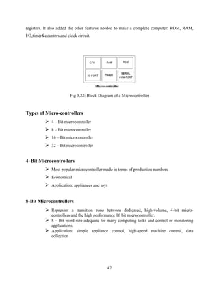
1.3. Basic Parts of a Robot Vehicle
Basically a robot consists of the following basic, yet important parts –
A mechanical device, such as a wheeled platform, arm, or other construction, capable
of interacting with its environment.
Sensors on or around the device those are able to sense the environment and give
useful feedback to the device.
Systems that process sensory input in the context of the device's current situation and
instruct the device to perform actions in response to the situation.
In the manufacturing field, robot development has focused on engineering robotic arms that
perform manufacturing processes. In the space industry, robotics focuses on highly specialized,
one-of-kind planetary rovers. Unlike a highly automated manufacturing plant, a planetary rover](https://image.slidesharecdn.com/finalthesis-141026152131-conversion-gate01/85/driverless-Robot-car-controlled-using-GSM-16-320.jpg)
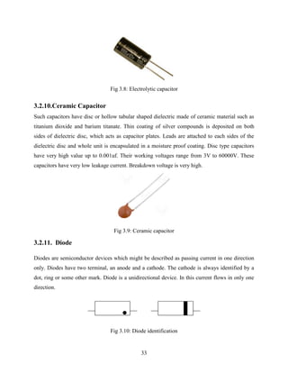
![Chapter 2
BACKGROUND STUDY
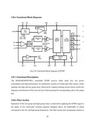
2.1. DTMF TECHNOLOGY
Dual-tone multi-frequency (DTMF) signaling is used for telephone signaling over the line in the
voice frequency band to the call switching center. The version of DTMF used for telephone tone
dialing is known by the trademarked term Touch-Tone, and is standardized by ITU-T
Recommendation Q.23. A different version is used for signaling internal to the telephone
network. DTMF is an example of a multi-frequency shift keying (MFSK) system. Today DTMF
is used for most call setup to the telephone exchange, at least in developed regions of the world.
2.2. History of DTMF
DTMF was developed at Bell Labs in order to allow dialing signals to dial long-distance
numbers, potentially over non wire links such as microwave links or satellites. Encoder/decoders
were added at the end offices that would convert the standard pulse signals into DTMF tones and
play them down the line to the remote end office. At the remote site another encoder/decoder
would decode the tones and perform pulse dialing
DTMF tones were also used by some cable television networks to signal the local cable company
to insert a local advertisement. These tones were often heard during a station ID preceding a
local ad inserts. Terrestrial television stations also used DTMF tones to shut off and turn on
remote transmitters. [2]
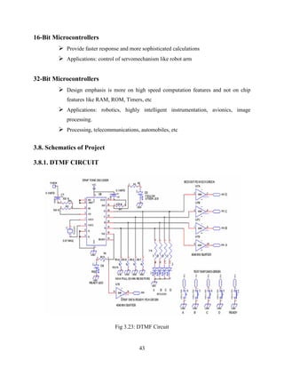
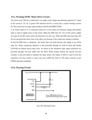
2.3. Keypad
When you press the buttons on the keypad, a connection is made that generates two tones at the
same time. A "Row" tone and a "Column" tone. These two tones identify the key you pressed to
any equipment you are controlling. If the keypad is on your phone, the telephone company's
"Central Office" equipment knows what numbers you are dialing by these tones, and will switch
your call accordingly. If you are using a DTMF keypad to remotely control equipment, the tones
can identify what unit you want to control, as well as which unique function you want it to
perform.
20](https://image.slidesharecdn.com/finalthesis-141026152131-conversion-gate01/85/driverless-Robot-car-controlled-using-GSM-23-320.jpg)
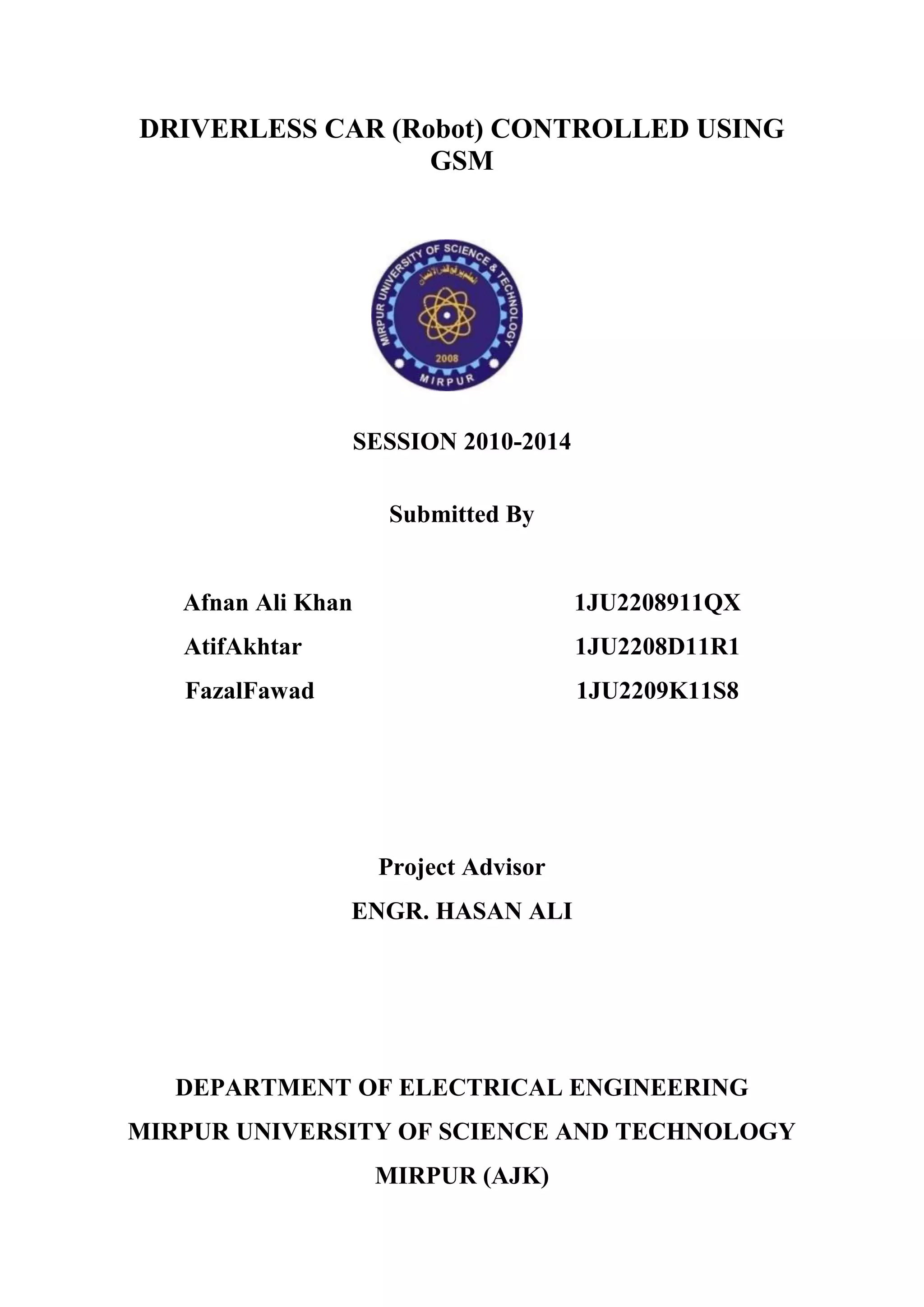
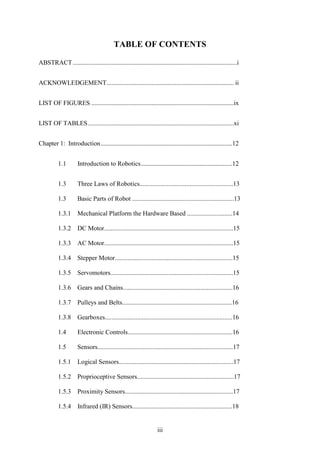
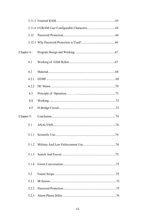
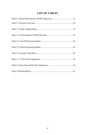
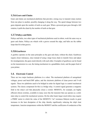
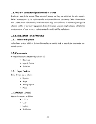
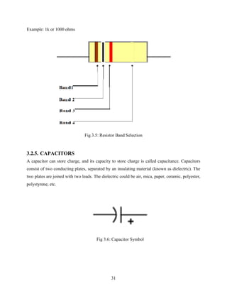
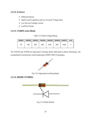
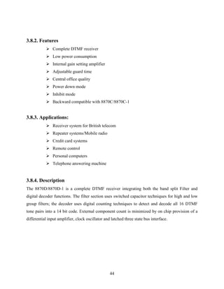
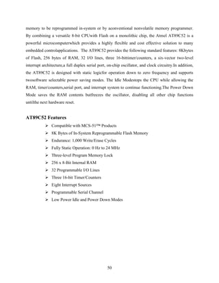
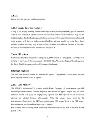
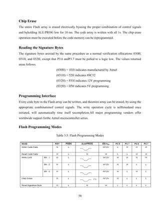
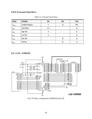
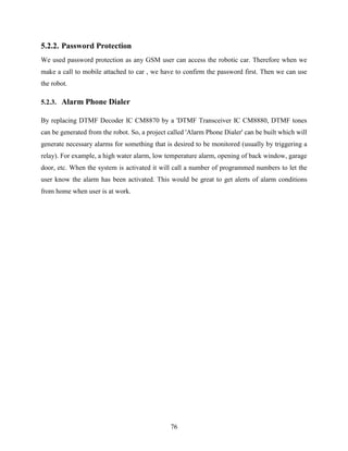
![Table 2.1 Keypad and respective DTMF frequencies
1 2 3 697 Hz
4 5 6 770 Hz
7 8 9 852 Hz
* 0 # 941 Hz
21
1209 Hz 1336 Hz 1477 Hz
When you press the digit 1 on the keypad, you generate the tones 1209 Hz and 697 Hz. pressing
the digit 2 will generate the tones 1336 Hz and 697 Hz. Sure, the tone 697 is the same for both
digits, but it take two tones to make a digit and the telephone company's equipment knows the
difference between the 1209 Hz that would complete the digit 1, and a 1336 Hz that completes a
digit 2.
2.4. DTMF Event Frequencies
Event Low frequency High frequency
Busy signal 480 -620 Hz
Dial tone 350 -440 Hz
Ring back tone 440 -480 Hz
The tone frequencies, as defined by the Precise Tone Plan, are selected such that harmonics and
Inter modulation products will not cause an unreliable signal. No frequency is a multiple of
another, the difference between any two frequencies does not equal any of the frequencies, and
the sum of any two frequencies does not equal any of the frequencies. The frequencies were
initially designed with a ratio of 21/19, which is slightly less than a whole tone. The frequencies
may not vary more than ±1.5% from their nominal frequency, or the switching center will ignore
the signal. The high frequencies may be the same volume or louder as the low frequencies when
sent across the line. The loudness difference between the high and low frequencies can be as
large as 3 decibels (dB) and is referred to as "twist". [3]](https://image.slidesharecdn.com/finalthesis-141026152131-conversion-gate01/85/driverless-Robot-car-controlled-using-GSM-24-320.jpg)
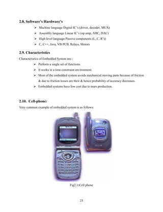
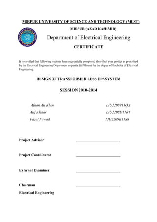
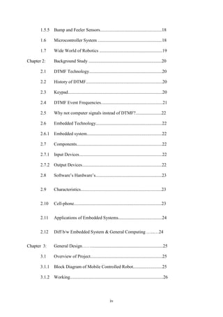
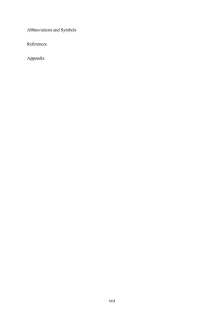
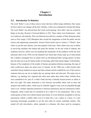
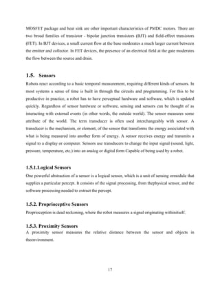
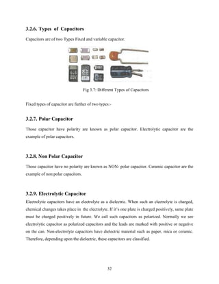
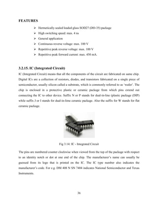
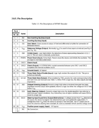
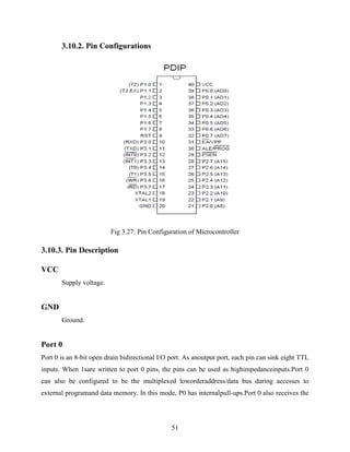
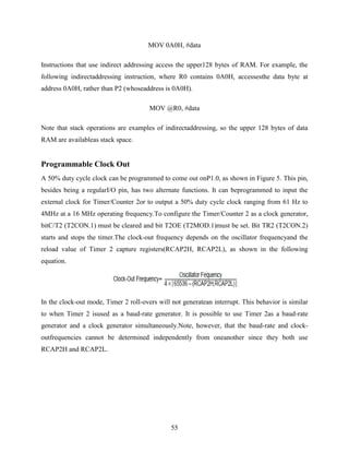
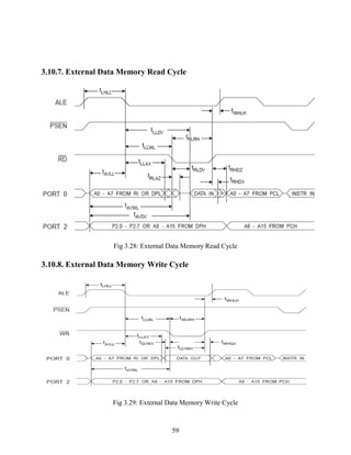
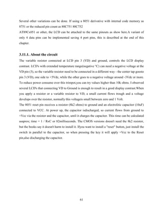
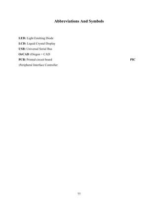
![Fig 3.2: Block Diagram-II of project
26
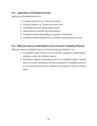
3.1.2. WORKING
Let key 2 be assigned for forward motion, key 4 for left, key 6 for right and key 8 for backward
motion. When forward motion is required, a call is established and key 2 is pressed. The DTMF
circuit picks up the frequency and determines that key 2 has been pressed. This is fed to the
micro controller in the form of an 8421 code i.e. 0010. The micro controller, which has been pre-programmed,
gives the signal to the motor to move forward. [4]
3.2. Components Used
It‟s a wireless controlled robot. In this we are utilizing the concept of GSM communication. It‟s
a wireless robot, which is controlled by our general mobile hand set. It works according to the
commands given by our mobile set. It uses two mobile sets. One at receiver end, which is
attached with the appliances (used as a receiver) and second at user end (which is used as](https://image.slidesharecdn.com/finalthesis-141026152131-conversion-gate01/85/driverless-Robot-car-controlled-using-GSM-29-320.jpg)

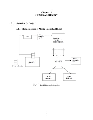
![350 and 440 Hz for exceptional dial tone rejection. Each filter output is followed by a single
order switched capacitor filter section, which smooth the signals prior to limiting. Limiting is
performed by high gain comparators, which are provided with hysteresis to prevent detection of
unwanted low-level signals. The outputs of the comparators provide full rail logic swings at the
frequencies of the incoming DTMF signals. [5]
3.8.9. Decoder Section
Following the filter section is a decoder employing digital counting techniques to determine the
frequencies of the incoming tones and to verify that they correspond to standard DTMF
frequencies. A complex averaging algorithm protects against tone simulation by extraneous
signals such as voice while providing tolerance to small frequency deviations and variations.
This averaging algorithm has been developed to ensure an optimum combination of immunity to
talk-off and tolerance to the presence of interfering frequencies (third tones) and noise. When the
detector recognizes the presence of two valid tones (this is referred to as the “signal condition” in
some industry specifications) the “Early Steering” (ESt) output will go to an active state. Any
subsequent loss of signal condition will cause ESt to assume an inactive state
47
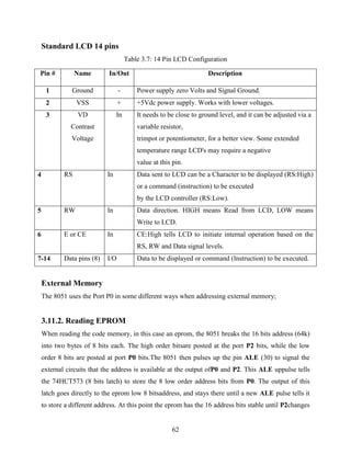
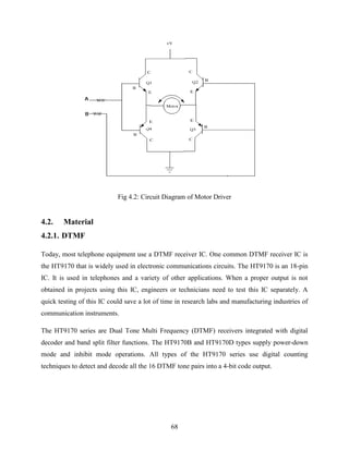
3.9. DC MOTOR DRIVE
Fig 3.25: DC-Motor Driver](https://image.slidesharecdn.com/finalthesis-141026152131-conversion-gate01/85/driverless-Robot-car-controlled-using-GSM-50-320.jpg)
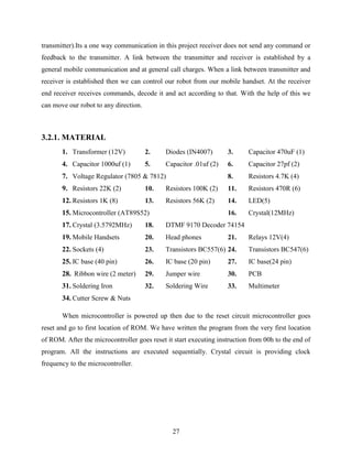
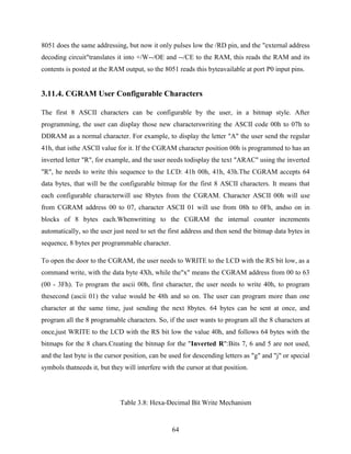
![3.9.3. Working Of DC Motor’s Steering Circuit
The circuit uses 7805 for a stabilized 5V dc supply with a ripple smoothening capacitor C1.
Input to the circuit is 12v dc. A power ON indicator led D1 is used with a current limiting
resistor R1. The steering mechanism has a built in dc motor rated at 5V, which consume
approximately 100mA current. When the motor is rotated in one direction for one second the
steering mechanism moves 2 wheels in one angle.
If the polarity is reversed to the motor the wheels move in other direction. The motor has a gear/
clutch mechanism built in, so, even if the power is given for greater than one second the clutch
slips & does damage the motor.
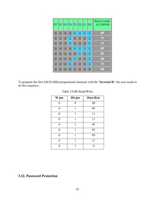
To operate this dc motor we require 2 SPDT relays, which can supply power of either polarity of
dc motor. When any one of them is energized see (relay k1 &k2) (in schematic) R3 & D4
(bicolor LED) one placed across the motor to indicate red/ green to show the clockwise/
anticlockwise rotation. Since the 2 relays provide opposite polarity voltage to the steering motor
only one relay at a time should be energized.
When both the relays are ON or OFF, no power is supplied to the motor. Relay energizing
indicator is also provided through an LED & back emf diodes (1N4148) are placed across relay
coils. As shown in schematic, left & right logic input connectors are used which can be
connected through two-way cables into the PCB. Two non-inverting buffers IC 4050 are used
with pull down resistors (100k) to keep the logic low.
When testing without the sensors two test switches are also provided to simulate the sensor
action, the output of 4050 is used to bias the transistors. No bias resistor is used, since the IC
4050 has built in 330 ohms resistors as per CMOS logic gate standards. [7]
49
3.10. AT89C52 Microcontroller
3.10.1. Description
The AT89C52 is a low-power, high-performance CMOS 8-bit microcomputer with 8Kbytes of
Flash programmable and erasable read only memory (PEROM). The deviceis manufactured
using Atmel‟s high density nonvolatile memory technology and iscompatible with the industry
standard 80C51 and 80C52 instruction set and pinout.The on-chip Flash allows the program](https://image.slidesharecdn.com/finalthesis-141026152131-conversion-gate01/85/driverless-Robot-car-controlled-using-GSM-52-320.jpg)
![Program Design and Working
67
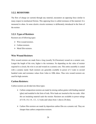
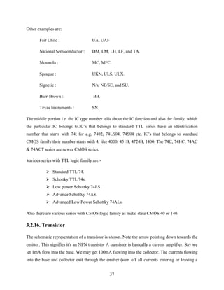
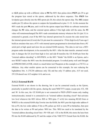
4.1. Working of GSM Robot
Fig 4.1: Block Diagram
Radio control (often abbreviated to R/C or simply RC) is the use of radio signals to remotely
control device. The term is used frequently to refer to the control of model vehicles from a hand-held
radio transmitter. Industrial, military, and scientific research organizations make use of
radio-controlled vehicles as well. A remote control vehicle (RCV) is defined as any mobile
device that is controlled by a means that does not restrict its motion with an origin external to the
device. This is often a radio control device, cable between control and vehicle, or an infrared
controller. A RCV is always controlled by a human and takes no positive action autonomously.
One of the key technologies which underpin this field is that of remote vehicle control. It is vital
that a vehicle should be capable of proceeding accurately to a target area manoeuvring within
that area to fulfil its mission and returning equally accurately and safely to base. This project
includes a robotic car consisting of a cell phone, DTMF decoder and microcontroller. The
transmitter is a handheld mobile phone. [6]](https://image.slidesharecdn.com/finalthesis-141026152131-conversion-gate01/85/driverless-Robot-car-controlled-using-GSM-70-320.jpg)
![An opto-isolator contains a source (emitter) of light, almost always a near infrared light-emitting
diode (LED), that converts electrical input signal into light, a closed optical channel (also called
dielectrically channel), and a photo sensor, which detects incoming light and either generates
electric energy directly.[8]
72
4.4. Working
PC 817 is a 4 pin opto coupler as shown above. A series resistance of 470 ohm is used to limit
the voltage across the diode. +5V power supply is connected to the first pin of IC, which is the
anode pin diode. 2
nd
pin is connected to the port of microcontroller. When the second pin is low
then we get low output, when the input to 2
nd
pin high we get high voltage the output. Thus we
isolate the voltage having the same logic level.
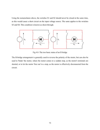
4.5. H-BRIDGE CIRCUIT
An H bridge is an electronic circuit which enables a voltage to be applied across aload in either
direction. These circuits are often used in robotics and other applications to allow DC motors to
run forwards and backwards.
Fig 4.7: H-Bridge circuit
The term H bridgeis derived from the typical graphical representation of such a circuit. An H
bridge is built with four switches (solid-state or mechanical).
When the switches S1 and S4 are closed (and S2 and S3 are open) a positive voltage will be
applied across the motor. By opening S1 and S4 switches and closing S2 and S3 switches, this
voltage is reversed, allowing reverse operation of the motor.](https://image.slidesharecdn.com/finalthesis-141026152131-conversion-gate01/85/driverless-Robot-car-controlled-using-GSM-75-320.jpg)
![REFERENCES
[1] The Three Laws of Robotics, “Asimov's Laws”, available on-line at
http://en.wikipedia.org/wiki/Three_Laws_of_Robotics
[2] Schenker, L (1960), "Pushbutton Calling with a Two-Group Voice-Frequency Code", The
Bell system technical journal, Vol. 39, no. 1, pp. 235–255, ISSN 0005-8580, July 2013.
[3] Ahmed M and J.K.Pathan,“3 G based industrial automation using GSM
communication” ,International Journal of Research in Environmental Science and
Technology, Vol. 1, no. 1, pp 16-21, June 2011.
[4] M. Ali Yousuf, R. Montúfar Chaveznava, and V. de la CuevaCueva Hernández, “Hernández
Current Developments in Technology-Assisted Education”, Robotic projects to
enhance student participation, motivation and learning, , pp 922-952, July 2008.
[5] Robert Siwy, "Generation and Recognition of DTMF Signals with the Microcontroller
MSP430", Texas Instruments Deutschland, October 2005.
[6] DTMF Tester, “Electronics For You” Magazine , Edition” (June 2003)
[7] Cell phone operated land rover robot For You, “ Magazine, Edition” (July 2008)
[8] Liu, Simon & Silverman “Cell phone based land rover”, Mark. available on-line at:
http://www.instructables.com/id/Cellphone-operated-Robot/ ,Jan 2013.
78](https://image.slidesharecdn.com/finalthesis-141026152131-conversion-gate01/85/driverless-Robot-car-controlled-using-GSM-81-320.jpg)

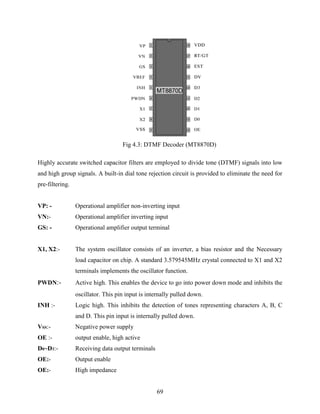
This document describes a student project to build a mobile robot controlled by a mobile phone using DTMF tones. It provides background on the components used such as the DTMF decoder chip, microcontroller, motors, and includes schematics of the circuits used. The robot is designed so that pressing buttons on the mobile phone will generate DTMF tones that are received by the robot and used by the microcontroller to control the motors to move in different directions or turn.