The document provides a comprehensive overview of the OSI model and TCP/IP model, detailing the seven layers of the OSI model, their functions, and characteristics. It explains each layer's responsibilities, including the physical, data link, network, transport, session, presentation, and application layers. Additionally, it discusses how TCP/IP facilitates reliable communication over the internet and its role in networking.
Pranab Bandhu Nath
(SeniorLecturer)
Department of CSE
City University, Dhaka.
Name : Maksudujjaman
ID : 1915002517
Batch : 50
th
Semester : Summer’21
Program : B.Sc. in CSE
Submitted By :
CITY UNIVERSITY
Faculty of Science and Engineering
Department of Computer Science & Engineering
CSE 317 Computer Networks, Summer’21
Supervised By :
This note is about the introduction of OSI Model & TCP/IP Model. It contains detailed of the
seven layers of the OSI Model which are Application layer, Presentation Layer, Session Layer,
Transport Layer, Network Layer, Data Link Layer, Physical Layer
Course Code: CSE 317
Course Title : Computer Networks
ABSTACT:
2.
OSI Model
OSI standsfor Open System Interconnection is a reference model that describes how information from
a software application in one computer moves through a physical medium to the software application in another
computer.
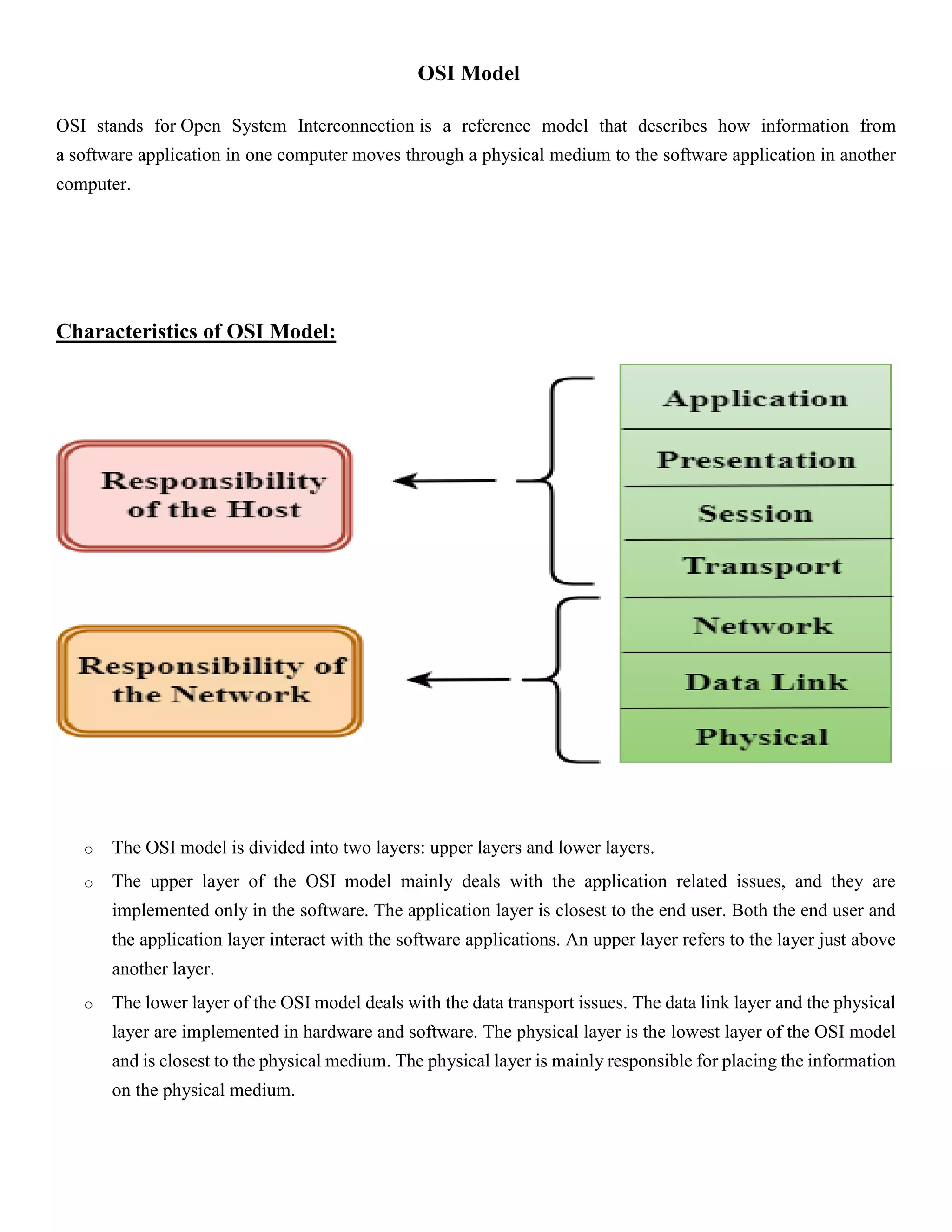
Characteristics of OSI Model:
o The OSI model is divided into two layers: upper layers and lower layers.
o The upper layer of the OSI model mainly deals with the application related issues, and they are
implemented only in the software. The application layer is closest to the end user. Both the end user and
the application layer interact with the software applications. An upper layer refers to the layer just above
another layer.
o The lower layer of the OSI model deals with the data transport issues. The data link layer and the physical
layer are implemented in hardware and software. The physical layer is the lowest layer of the OSI model
and is closest to the physical medium. The physical layer is mainly responsible for placing the information
on the physical medium.
3.
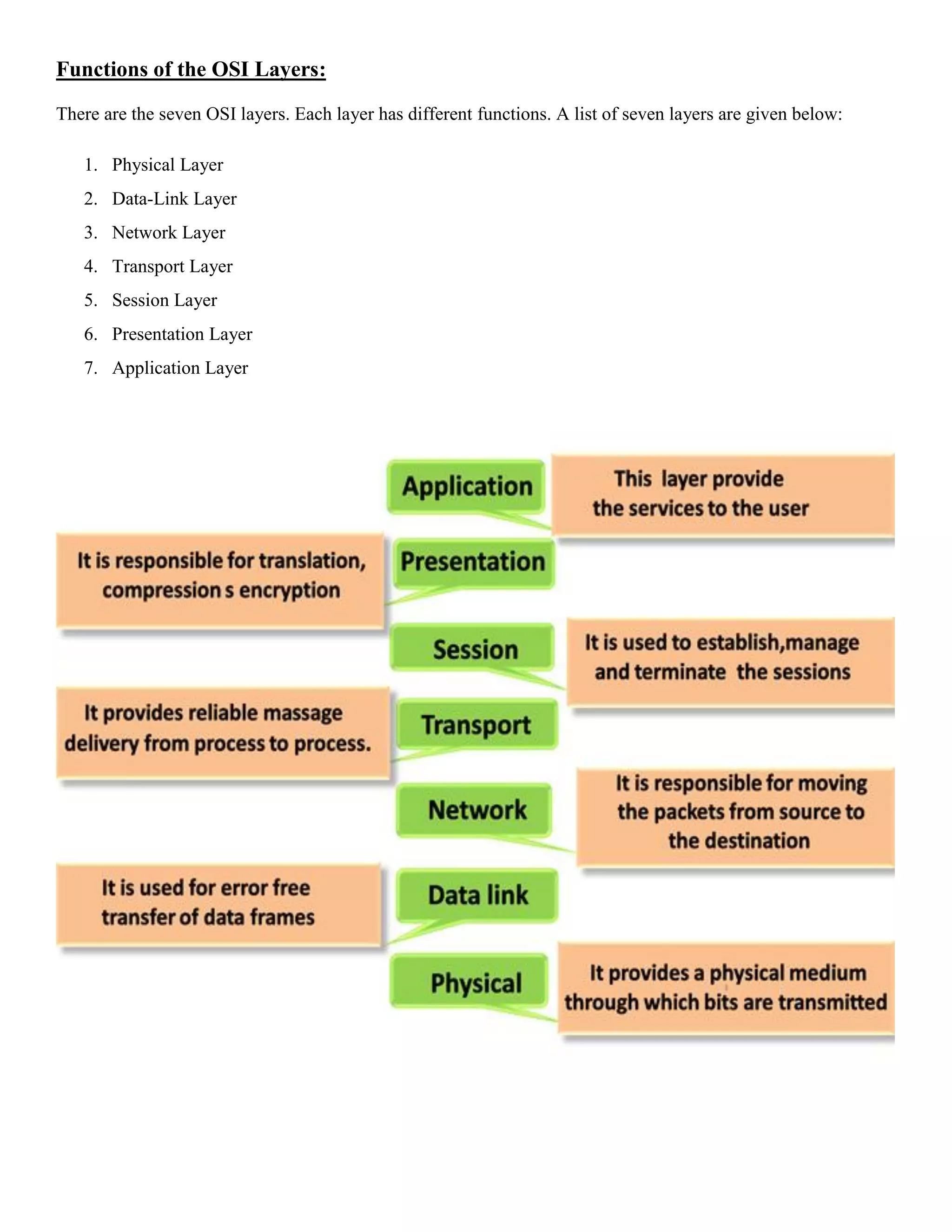
Functions of theOSI Layers:
There are the seven OSI layers. Each layer has different functions. A list of seven layers are given below:
1. Physical Layer
2. Data-Link Layer
3. Network Layer
4. Transport Layer
5. Session Layer
6. Presentation Layer
7. Application Layer
4.
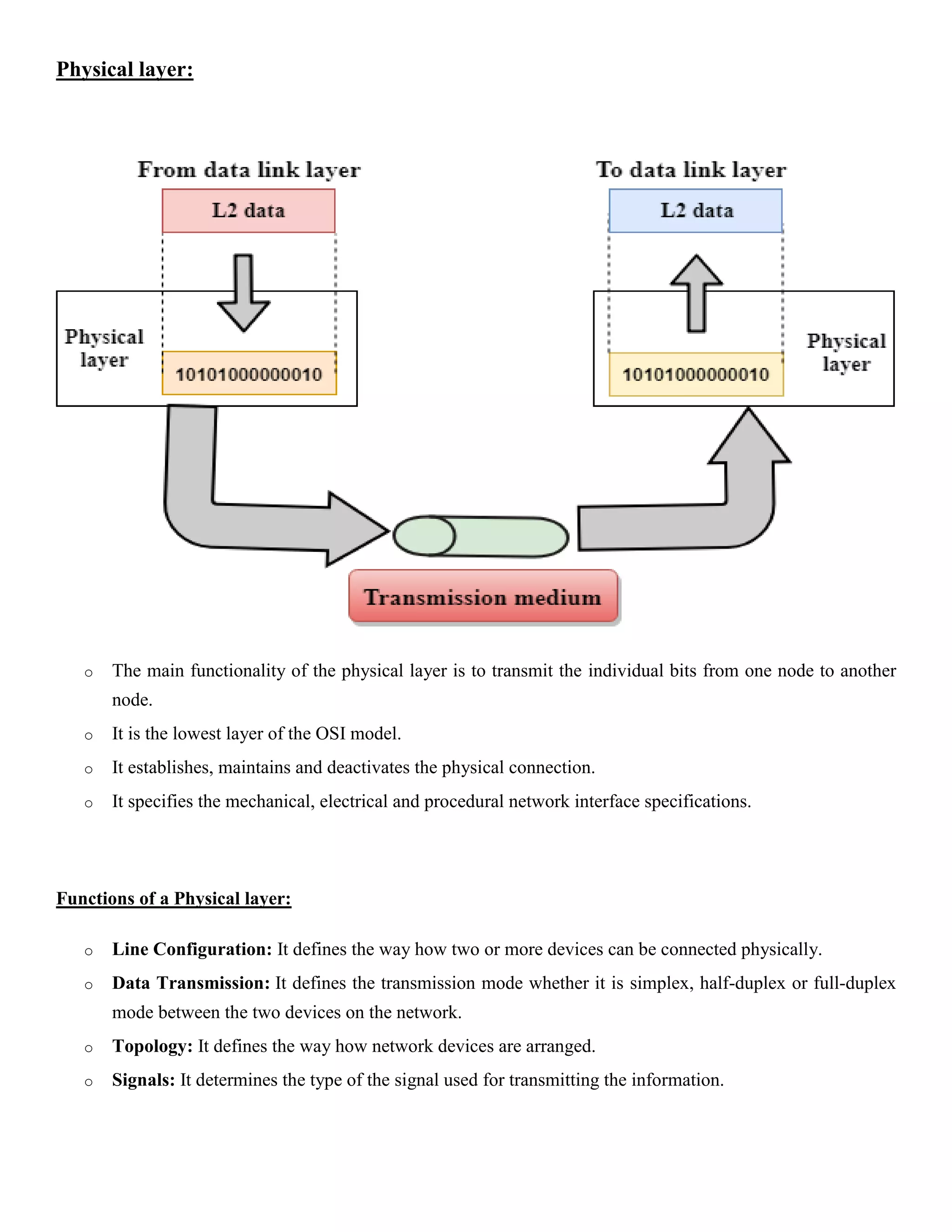
Physical layer:
o Themain functionality of the physical layer is to transmit the individual bits from one node to another
node.
o It is the lowest layer of the OSI model.
o It establishes, maintains and deactivates the physical connection.
o It specifies the mechanical, electrical and procedural network interface specifications.
Functions of a Physical layer:
o Line Configuration: It defines the way how two or more devices can be connected physically.
o Data Transmission: It defines the transmission mode whether it is simplex, half-duplex or full-duplex
mode between the two devices on the network.
o Topology: It defines the way how network devices are arranged.
o Signals: It determines the type of the signal used for transmitting the information.
5.
Data-Link Layer:
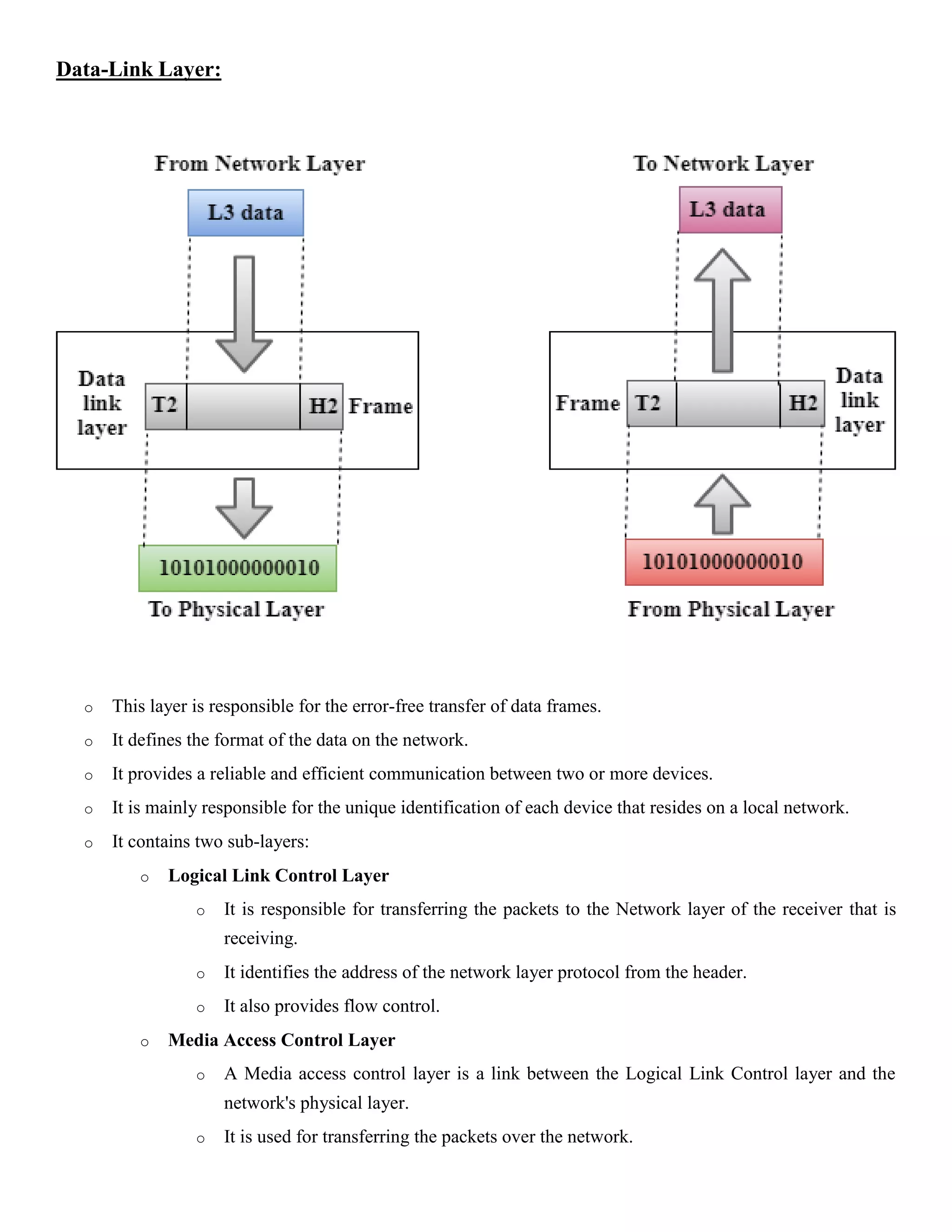
o Thislayer is responsible for the error-free transfer of data frames.
o It defines the format of the data on the network.
o It provides a reliable and efficient communication between two or more devices.
o It is mainly responsible for the unique identification of each device that resides on a local network.
o It contains two sub-layers:
o Logical Link Control Layer
o It is responsible for transferring the packets to the Network layer of the receiver that is
receiving.
o It identifies the address of the network layer protocol from the header.
o It also provides flow control.
o Media Access Control Layer
o A Media access control layer is a link between the Logical Link Control layer and the
network's physical layer.
o It is used for transferring the packets over the network.
6.
Functions of theData-link layer:
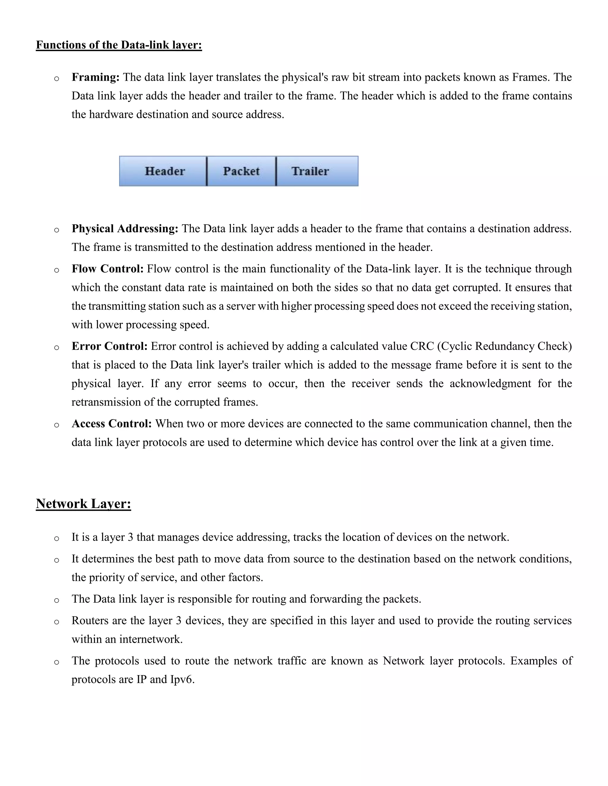
o Framing: The data link layer translates the physical's raw bit stream into packets known as Frames. The
Data link layer adds the header and trailer to the frame. The header which is added to the frame contains
the hardware destination and source address.
o Physical Addressing: The Data link layer adds a header to the frame that contains a destination address.
The frame is transmitted to the destination address mentioned in the header.
o Flow Control: Flow control is the main functionality of the Data-link layer. It is the technique through
which the constant data rate is maintained on both the sides so that no data get corrupted. It ensures that
the transmitting station such as a server with higher processing speed does not exceed the receiving station,
with lower processing speed.
o Error Control: Error control is achieved by adding a calculated value CRC (Cyclic Redundancy Check)
that is placed to the Data link layer's trailer which is added to the message frame before it is sent to the
physical layer. If any error seems to occur, then the receiver sends the acknowledgment for the
retransmission of the corrupted frames.
o Access Control: When two or more devices are connected to the same communication channel, then the
data link layer protocols are used to determine which device has control over the link at a given time.
Network Layer:
o It is a layer 3 that manages device addressing, tracks the location of devices on the network.
o It determines the best path to move data from source to the destination based on the network conditions,
the priority of service, and other factors.
o The Data link layer is responsible for routing and forwarding the packets.
o Routers are the layer 3 devices, they are specified in this layer and used to provide the routing services
within an internetwork.
o The protocols used to route the network traffic are known as Network layer protocols. Examples of
protocols are IP and Ipv6.
7.
Functions of NetworkLayer:
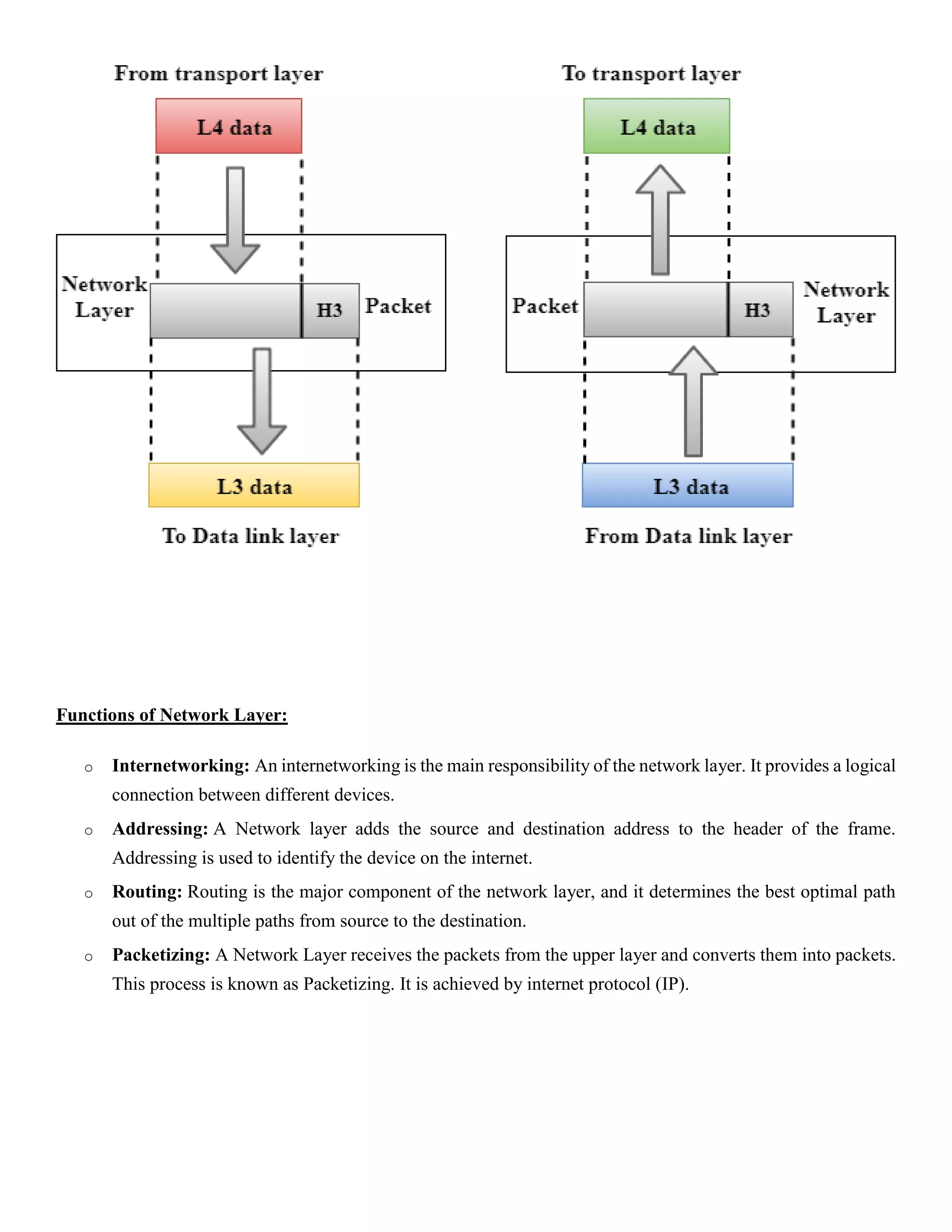
o Internetworking: An internetworking is the main responsibility of the network layer. It provides a logical
connection between different devices.
o Addressing: A Network layer adds the source and destination address to the header of the frame.
Addressing is used to identify the device on the internet.
o Routing: Routing is the major component of the network layer, and it determines the best optimal path
out of the multiple paths from source to the destination.
o Packetizing: A Network Layer receives the packets from the upper layer and converts them into packets.
This process is known as Packetizing. It is achieved by internet protocol (IP).
8.
Transport Layer:
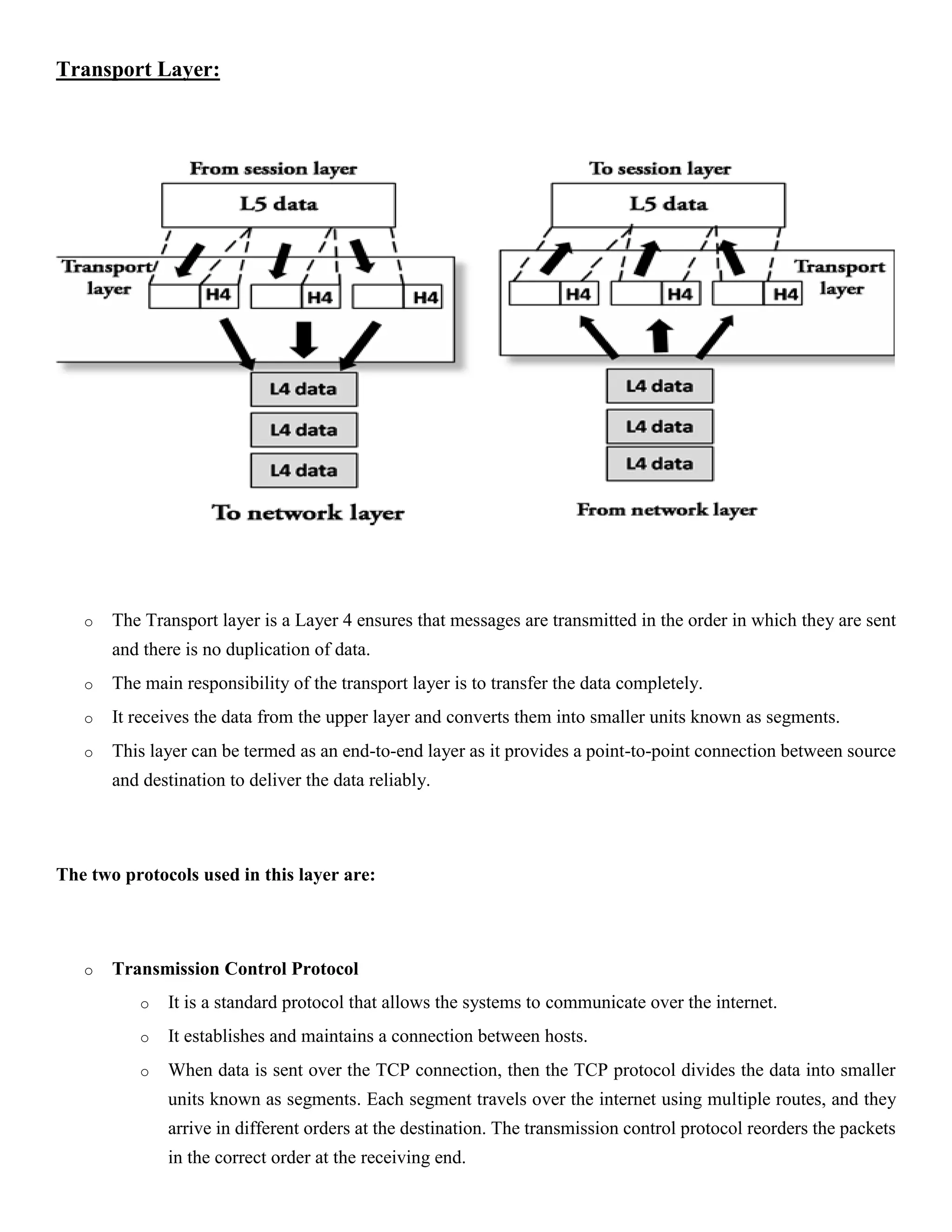
o TheTransport layer is a Layer 4 ensures that messages are transmitted in the order in which they are sent
and there is no duplication of data.
o The main responsibility of the transport layer is to transfer the data completely.
o It receives the data from the upper layer and converts them into smaller units known as segments.
o This layer can be termed as an end-to-end layer as it provides a point-to-point connection between source
and destination to deliver the data reliably.
The two protocols used in this layer are:
o Transmission Control Protocol
o It is a standard protocol that allows the systems to communicate over the internet.
o It establishes and maintains a connection between hosts.
o When data is sent over the TCP connection, then the TCP protocol divides the data into smaller
units known as segments. Each segment travels over the internet using multiple routes, and they
arrive in different orders at the destination. The transmission control protocol reorders the packets
in the correct order at the receiving end.
9.
o User DatagramProtocol
o User Datagram Protocol is a transport layer protocol.
o It is an unreliable transport protocol as in this case receiver does not send any acknowledgment
when the packet is received, the sender does not wait for any acknowledgment. Therefore, this
makes a protocol unreliable.
Functions of Transport Layer:
o Service-point addressing: Computers run several programs simultaneously due to this reason, the
transmission of data from source to the destination not only from one computer to another computer but
also from one process to another process. The transport layer adds the header that contains the address
known as a service-point address or port address. The responsibility of the network layer is to transmit the
data from one computer to another computer and the responsibility of the transport layer is to transmit the
message to the correct process.
o Segmentation and reassembly: When the transport layer receives the message from the upper layer, it
divides the message into multiple segments, and each segment is assigned with a sequence number that
uniquely identifies each segment. When the message has arrived at the destination, then the transport layer
reassembles the message based on their sequence numbers.
o Connection control: Transport layer provides two services Connection-oriented service and
connectionless service. A connectionless service treats each segment as an individual packet, and they all
travel in different routes to reach the destination. A connection-oriented service makes a connection with
the transport layer at the destination machine before delivering the packets. In connection-oriented service,
all the packets travel in the single route.
o Flow control: The transport layer also responsible for flow control but it is performed end-to-end rather
than across a single link.
o Error control: The transport layer is also responsible for Error control. Error control is performed end-
to-end rather than across the single link. The sender transport layer ensures that message reach at the
destination without any error.
10.
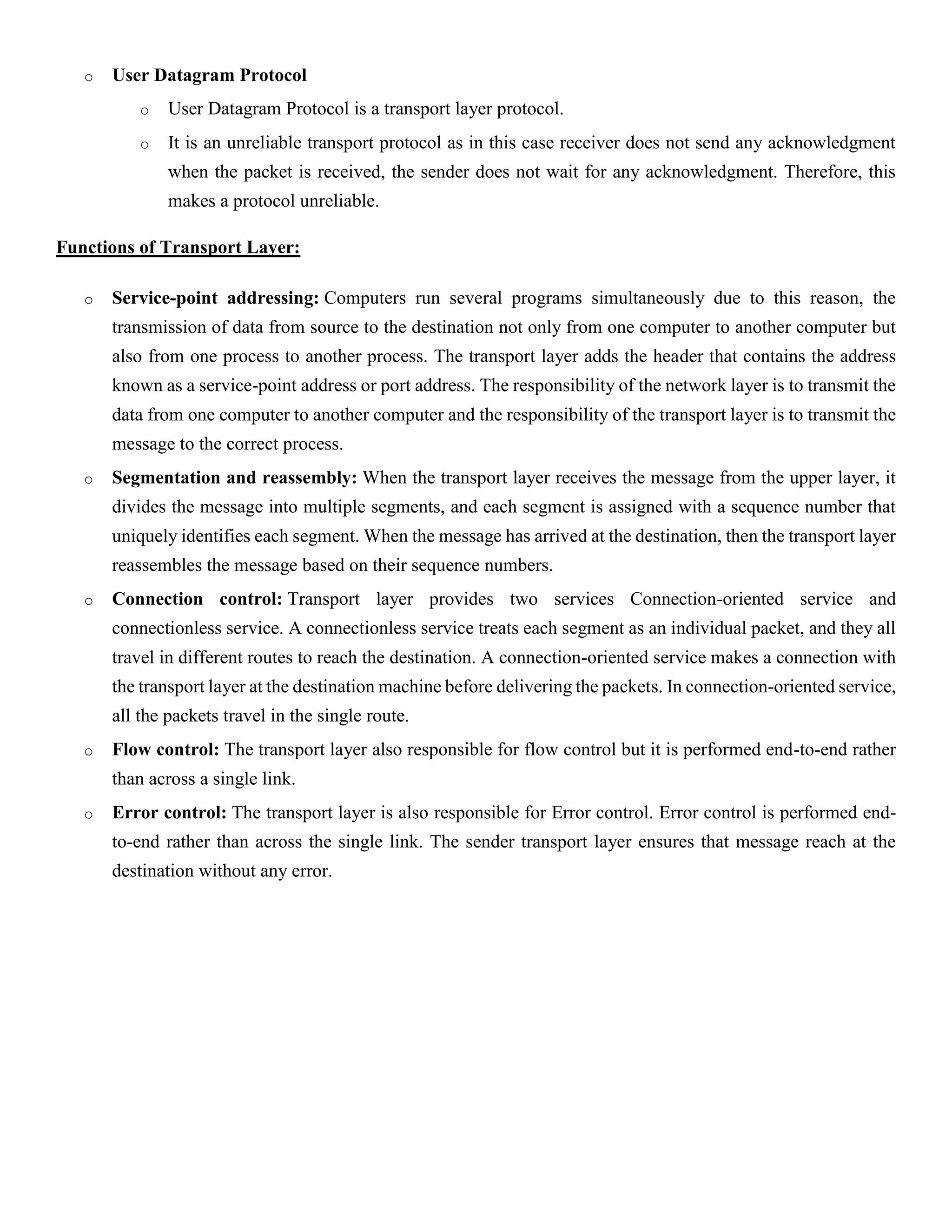
Session Layer:
o Itis a layer 3 in the OSI model.
o The Session layer is used to establish, maintain and synchronizes the interaction between communicating
devices.
Functions of Session layer:
o Dialog control: Session layer acts as a dialog controller that creates a dialog between two processes or
we can say that it allows the communication between two processes which can be either half-duplex or
full-duplex.
o Synchronization: Session layer adds some checkpoints when transmitting the data in a sequence. If some
error occurs in the middle of the transmission of data, then the transmission will take place again from the
checkpoint. This process is known as Synchronization and recovery.
11.
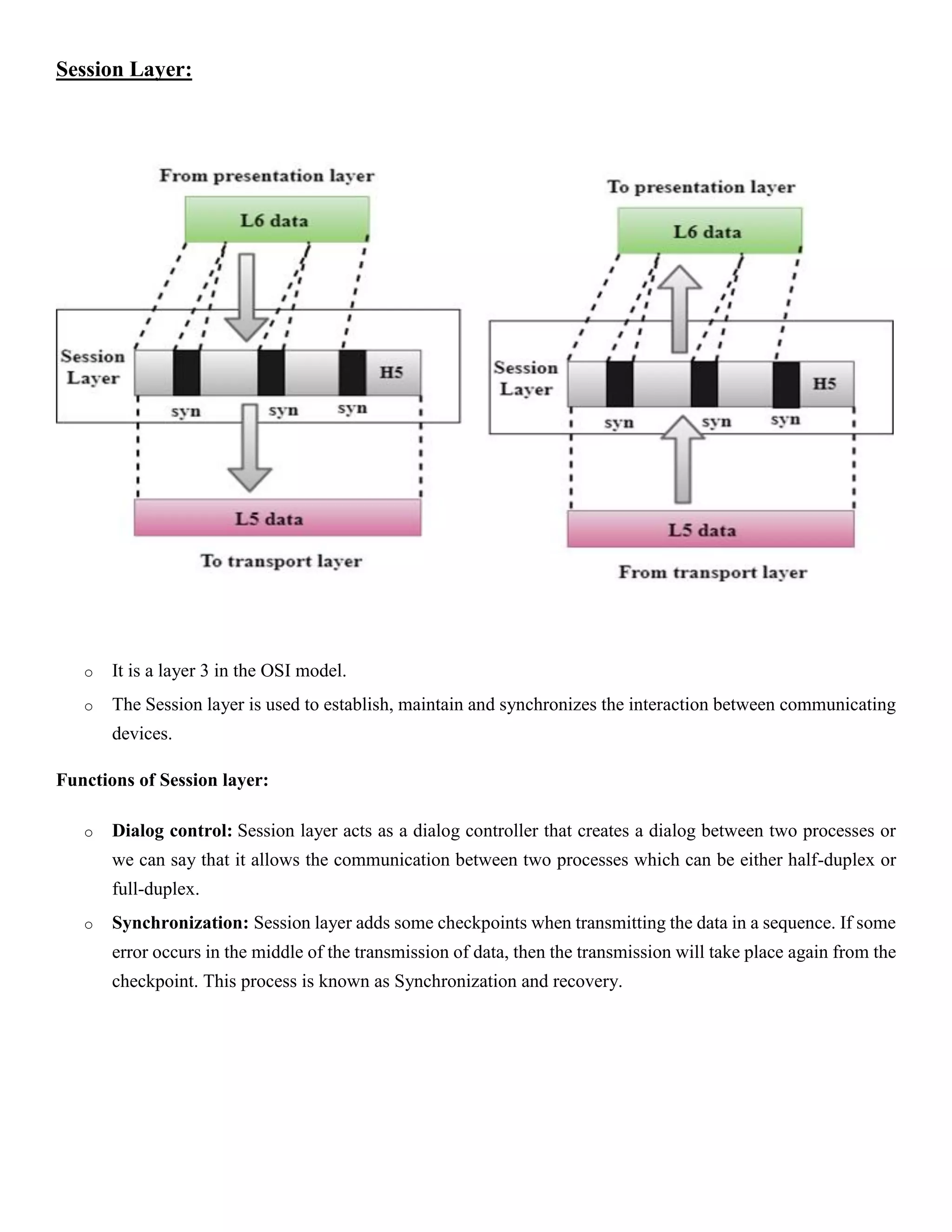
Presentation Layer:
o APresentation layer is mainly concerned with the syntax and semantics of the information exchanged
between the two systems.
o It acts as a data translator for a network.
o This layer is a part of the operating system that converts the data from one presentation format to another
format.
o The Presentation layer is also known as the syntax layer.
Functions of Presentation layer:
o Translation: The processes in two systems exchange the information in the form of character strings,
numbers and so on. Different computers use different encoding methods, the presentation layer handles
the interoperability between the different encoding methods. It converts the data from sender-dependent
format into a common format and changes the common format into receiver-dependent format at the
receiving end.
o Encryption: Encryption is needed to maintain privacy. Encryption is a process of converting the sender-
transmitted information into another form and sends the resulting message over the network.
o Compression: Data compression is a process of compressing the data, i.e., it reduces the number of bits
to be transmitted. Data compression is very important in multimedia such as text, audio, video.
12.
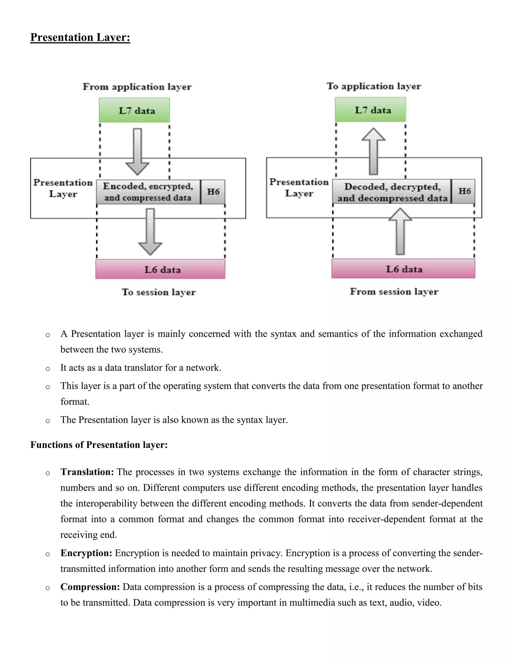
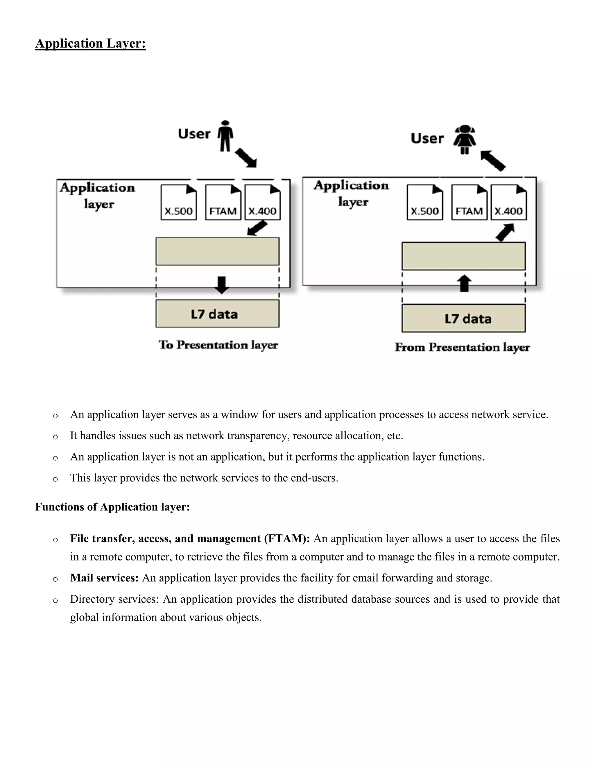
Application Layer:
o Anapplication layer serves as a window for users and application processes to access network service.
o It handles issues such as network transparency, resource allocation, etc.
o An application layer is not an application, but it performs the application layer functions.
o This layer provides the network services to the end-users.
Functions of Application layer:
o File transfer, access, and management (FTAM): An application layer allows a user to access the files
in a remote computer, to retrieve the files from a computer and to manage the files in a remote computer.
o Mail services: An application layer provides the facility for email forwarding and storage.
o Directory services: An application provides the distributed database sources and is used to provide that
global information about various objects.
13.
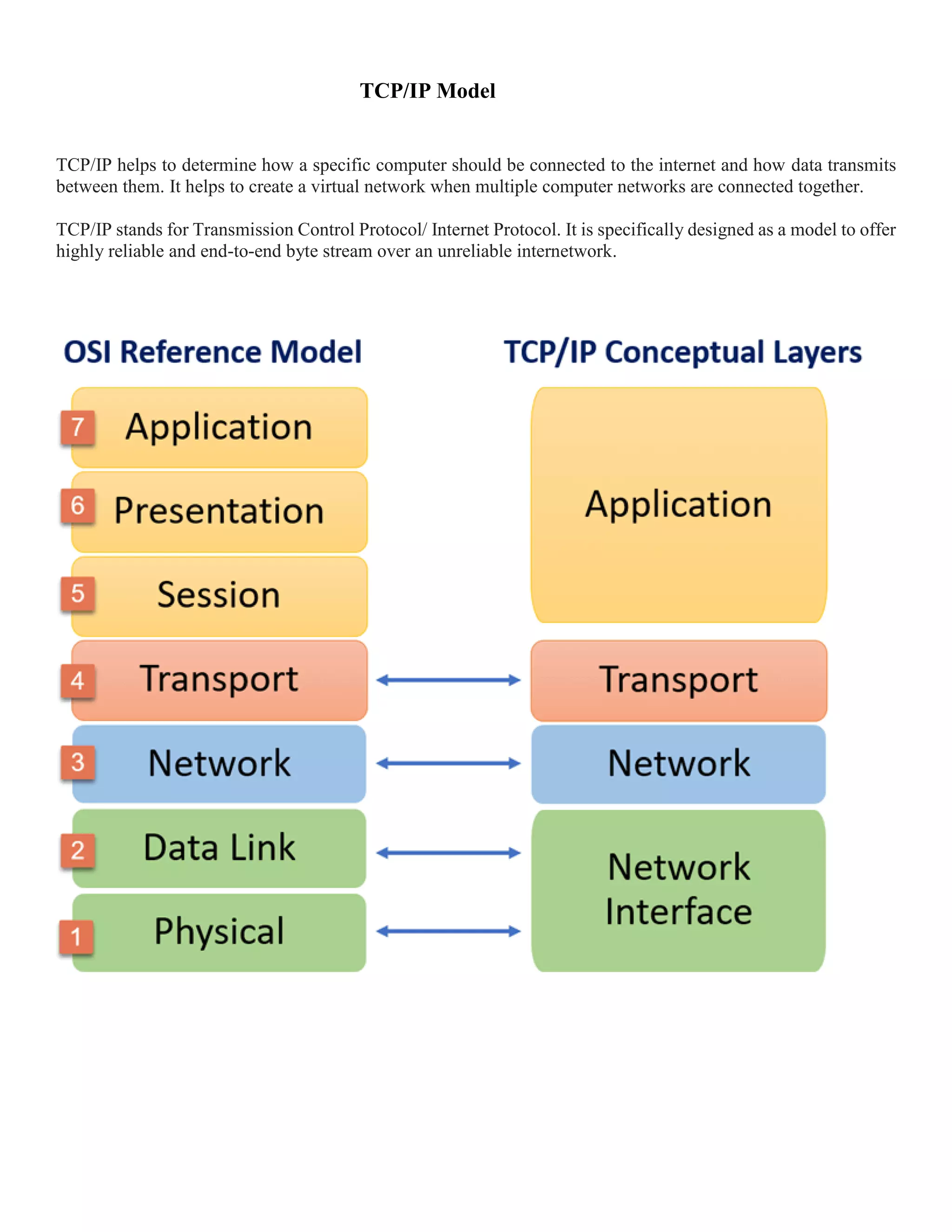
TCP/IP Model
TCP/IP helpsto determine how a specific computer should be connected to the internet and how data transmits
between them. It helps to create a virtual network when multiple computer networks are connected together.
TCP/IP stands for Transmission Control Protocol/ Internet Protocol. It is specifically designed as a model to offer
highly reliable and end-to-end byte stream over an unreliable internetwork.