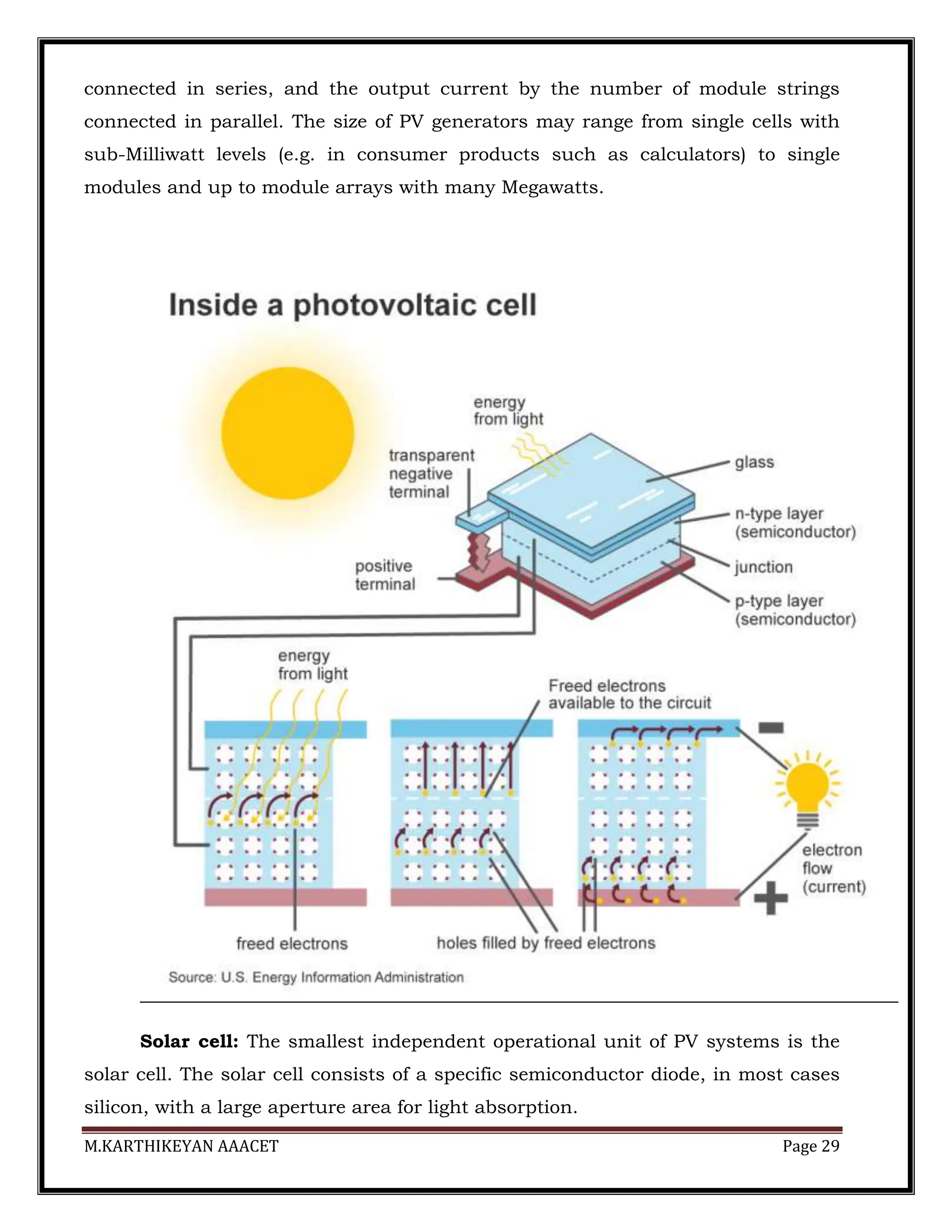
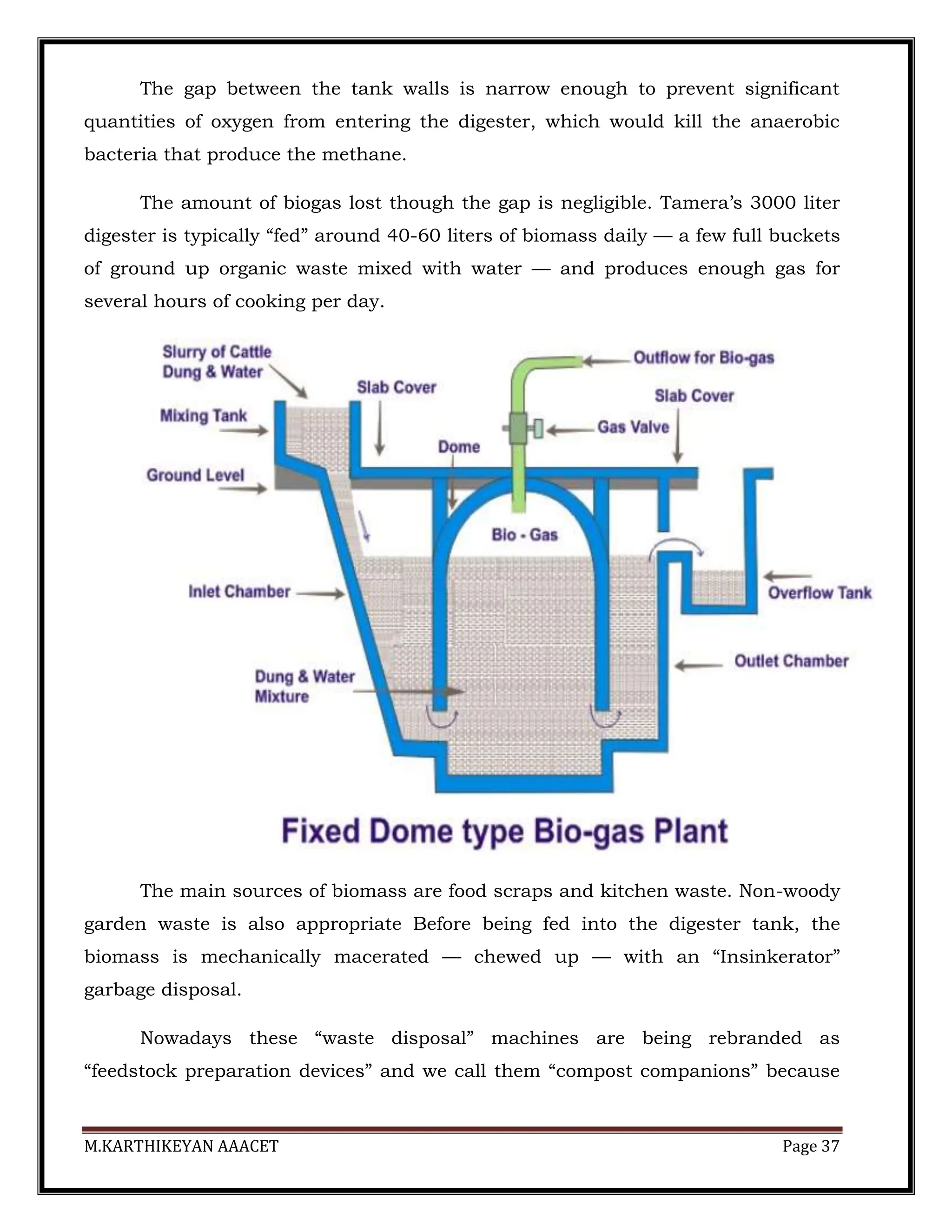
The document discusses the importance of renewable energy sources, particularly in the context of solar power, highlighting their advantages such as sustainability and lower environmental impact compared to fossil fuels. It provides an overview of renewable energy technologies and their growing significance in India, as well as specifics about solar energy collection methods and systems. Additionally, it outlines the principles of solar radiation and details various types of solar collectors and their applications.
![M.KARTHIKEYAN AAACET Page 3
Additional smaller hydroelectric power units with a total capacity of 4,380
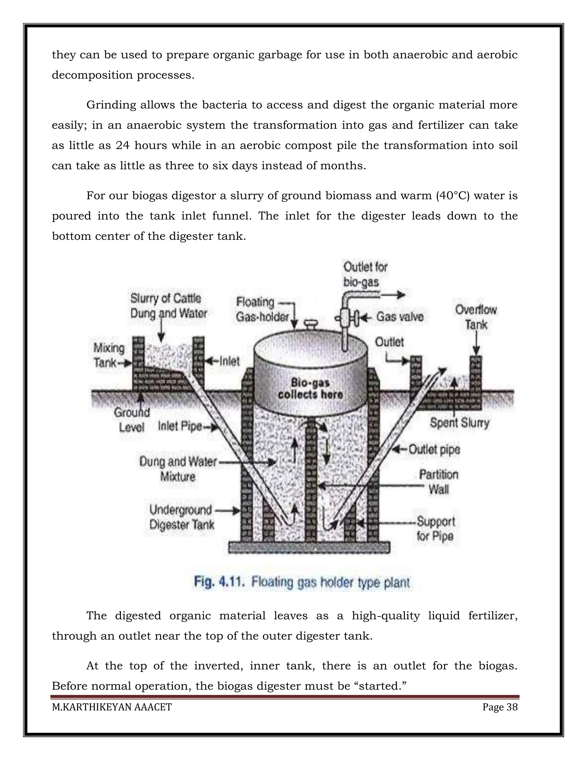
MW (1.3% of its total utility power generation capacity) have been installed.
Small hydropower, defined to be generated at facilities with nameplate
capacities up to 25 MW, comes under the ambit of the Ministry of New and
Renewable energy (MNRE); whilst large hydro, defined as above 25 MW,
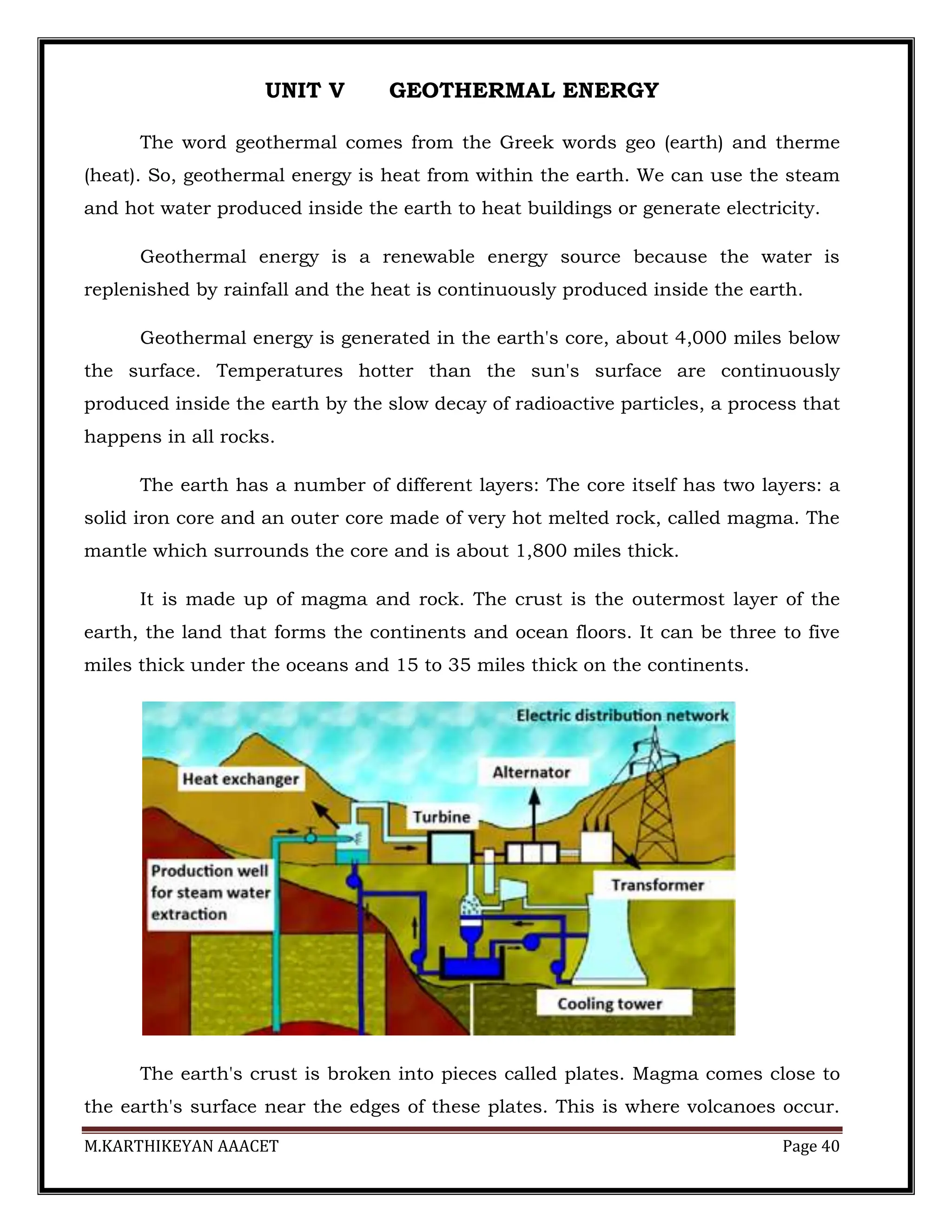
comes under the ambit of Ministry of Power.
1] SOLAR PHOTOVOLTAIC SYSTEM
Photovoltaic system, also PV system or solar power system, is a power
system designed to supply solar power by means of photovoltaics.
It consists of
Solar panels to absorb and convert sunlight into electricity,
Solar inverter to change the electric current from DC to AC.](https://image.slidesharecdn.com/lecturenotesfor5units-240420063843-f47c15bb/75/ORO551-RENEWABLE-ENERGY-SOURCES-FULL-NOTES-3-2048.jpg)
![M.KARTHIKEYAN AAACET Page 4
2] SOLAR WATER HEATING
Solar water heating (SWH) is the conversion of sunlight into heat for water
heating using a solar thermal collector.
3] SOLAR THERMAL POWER PLANT
Solar thermal energy (STE) is a form of energy and a technology for
harnessing solar energy to generate electrical energy for use in industry,
and in the residential and commercial sectors.](https://image.slidesharecdn.com/lecturenotesfor5units-240420063843-f47c15bb/75/ORO551-RENEWABLE-ENERGY-SOURCES-FULL-NOTES-4-2048.jpg)
![M.KARTHIKEYAN AAACET Page 5
4] SOLAR COOKER
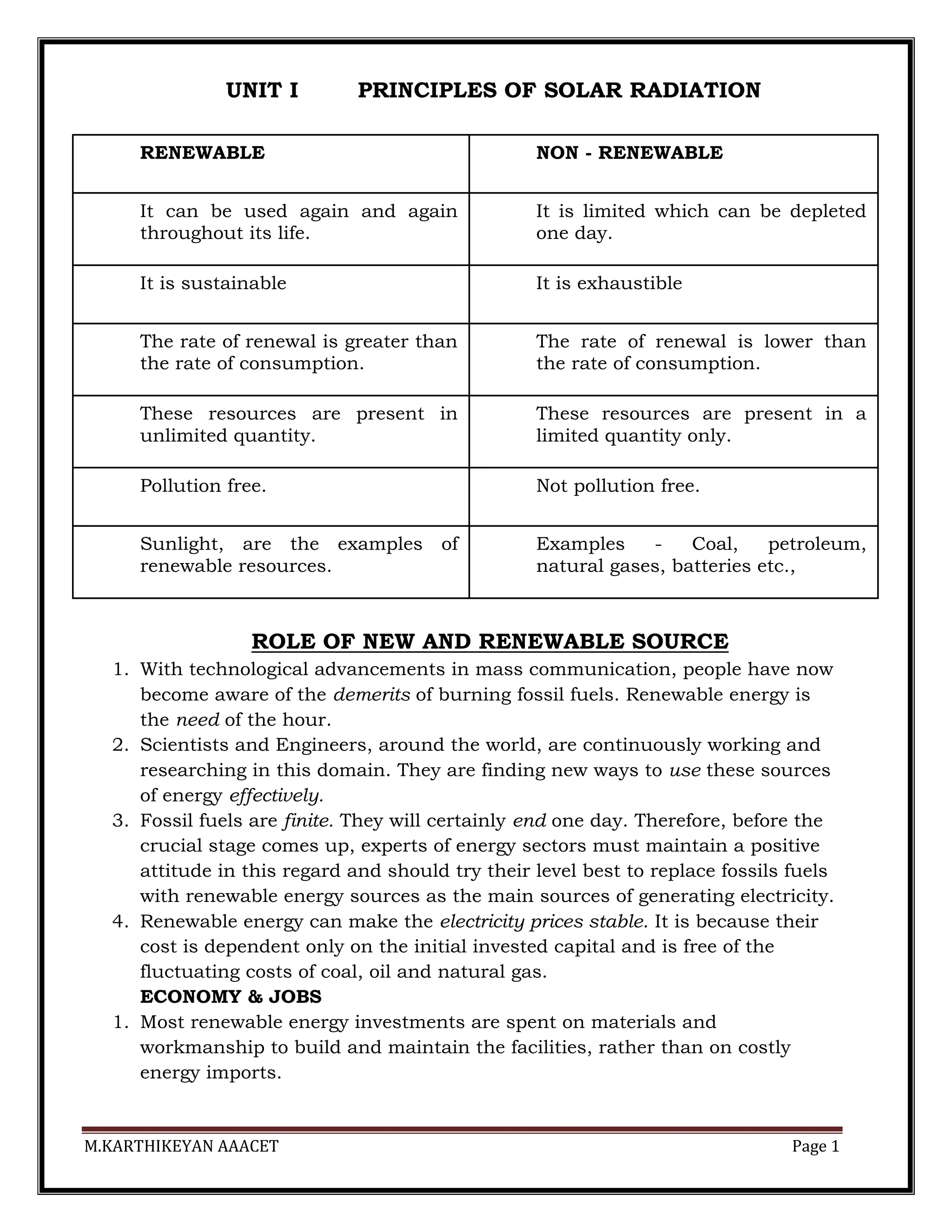
EXTRATERRESTRIAL / TERRESTRIAL SOLAR RADIATION](https://image.slidesharecdn.com/lecturenotesfor5units-240420063843-f47c15bb/75/ORO551-RENEWABLE-ENERGY-SOURCES-FULL-NOTES-5-2048.jpg)
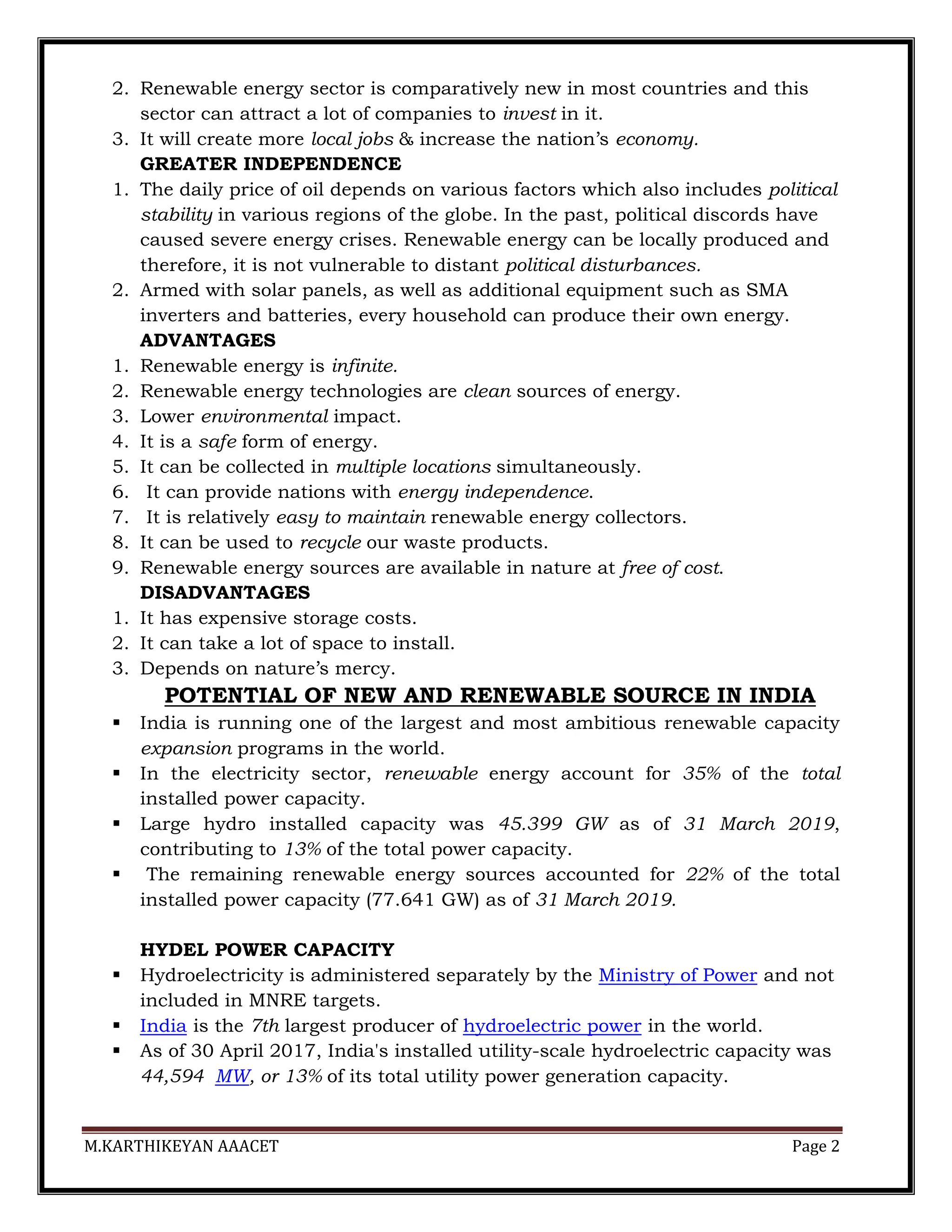
![M.KARTHIKEYAN AAACET Page 7
INSTRUMENTS FOR MEASURING SOLAR RADIATION
To measure global or diffuse radiation:
I. PYRANOMETER
1. Eppley Pyranometer
2. Yellot solarimeter [photovoltaic cell pyranometer]
3. Moll – Goreczynski Pyranometer
4. Bimetallic Pyranograph
5. Yanishevsky Pyranometer
6. Dirmhirn-Sauberer or Star Pyranometer
To measure beam or direct radiation:
II. PYRHELIOMETER
1. Angstrom pyreheliometer
2. Abbot silver disc pyreheliometer
3. Eppley pyreheliometer
PYRANOMETER
A pyranometer is used to measure global solar radiation falling on a
horizontal surface.
Pyranometer also measure diffused radiation by using a shading ring.
The shading ring will prevent the falling of beam radiation on the sensor.
Its sensor has a horizontal radiation-sensing surface that absorbs solar
radiation energy from the whole sky and transforms this energy into heat.
Global solar radiation can be calculated by measuring this heat energy.
Most pyranometers in general use are now the thermopile type, although
bimetallic pyranometers are occasionally found.
BIMETALLIC PYRANOGRAPH
A bimetallic strip is used to convert a temperature change into mechanical
displacement.
A bimetal strip is made of two thin metal strips that have different
coefficients of expansion.
The two metal strips are joined by brazing, so that the relative movement
between them is stopped.](https://image.slidesharecdn.com/lecturenotesfor5units-240420063843-f47c15bb/75/ORO551-RENEWABLE-ENERGY-SOURCES-FULL-NOTES-7-2048.jpg)
![M.KARTHIKEYAN AAACET Page 11
conduction loss can be reduced by thermal insulation.
7. In order to reduce the heat lost by re-radiation from the top of the absorber
plate of a flat plate collector, it is usual to put a selective coating on the
plate.
8. The selective coating exhibits the characteristic of a high value of
absorptivity for incoming solar radiation and a low value of
emissivity for outgoing re-radiation.
9. As a result, the collection efficiency of the flat plate collector is improved.
FACTORS AFFECTING THE PERFORMANCE OF SYSTEM ARE
1. Incident Solar Radiation.
2. Number of Cover Plate = More than two cover plate should not be used.
3. Spacing = spacing between absorber and cover plate is kept 2-3 cm.
4. Collector Tilt = optimum tilt angle is kept +/-15 °
5. Inlet Temperature = low temperature fluid absorbs more heat.
6. Dust on cover Plate = Frequent cleaning is required
ADVANTAGES
1. Collect both beam and diffuse radiation
2. Permanently fixed (no sophisticated positioning or tracking equipment is
required)
3. Easy to manufacture
4. Low cost
5. Little maintenance
APPLICATIONS
1. Domestic water heating system.
2. For heating swimming pools.
3. Solar heating dryers.
4. Solarium
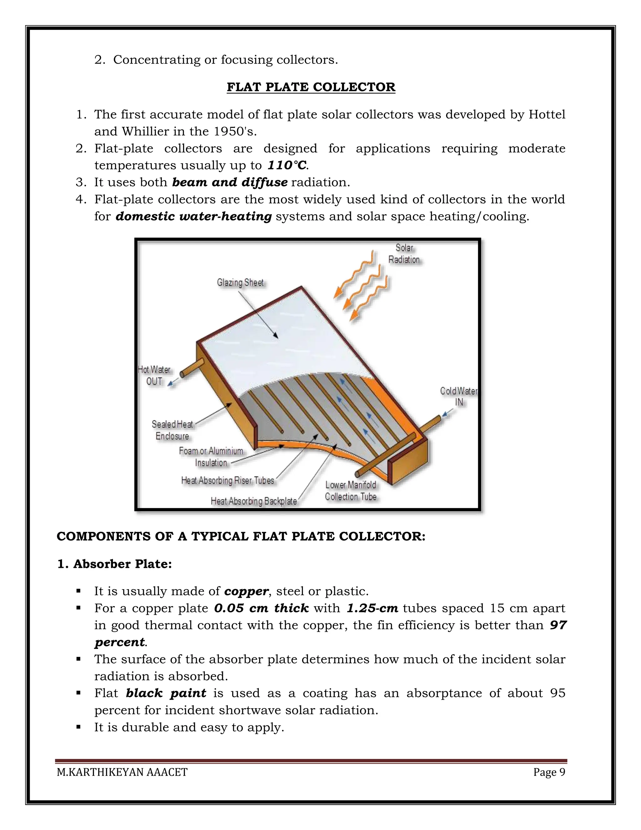
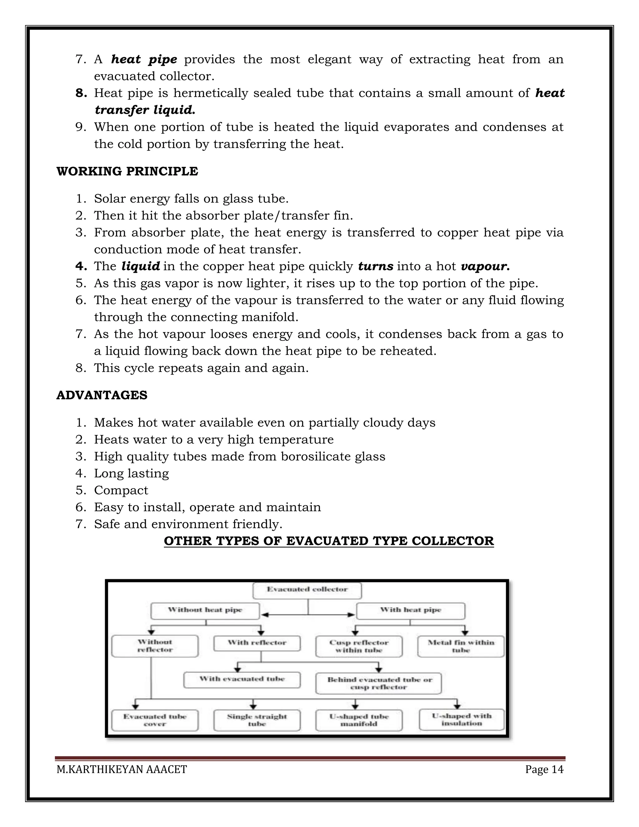
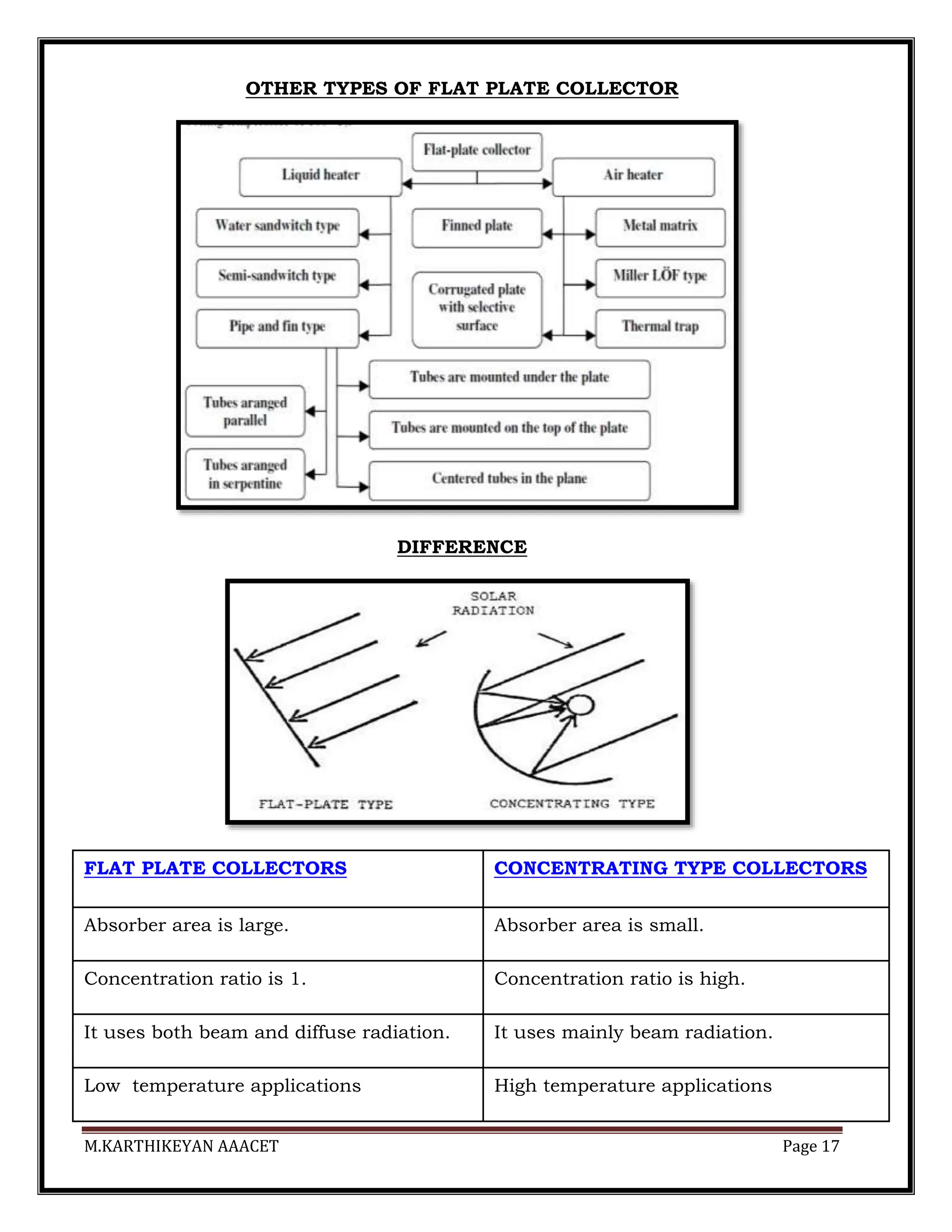
TYPES OF FLAT PLATE COLLECTOR
1. Modified Flat Plate Collector
2. Evacuated Tube Collector
3. Solar Air Heater
1.] MODIFIED FLAT PLATE COLLECTOR](https://image.slidesharecdn.com/lecturenotesfor5units-240420063843-f47c15bb/75/ORO551-RENEWABLE-ENERGY-SOURCES-FULL-NOTES-11-2048.jpg)
![M.KARTHIKEYAN AAACET Page 12
CONSTRUCTION & WORKING - refer flat plate collector - In addition to that .,
1. Modified flat plate collector have reflective side faces (mirror) .
2. With the help of mirror higher concentration upto 10 is achieved & higher
temperature of working fluids upto 200°c is achieved.
3. Modified flat plate collector is aligned in East-West direction and it requires
a periodic tilt adjustment.
2.] EVACUATED TUBE COLLECTOR](https://image.slidesharecdn.com/lecturenotesfor5units-240420063843-f47c15bb/75/ORO551-RENEWABLE-ENERGY-SOURCES-FULL-NOTES-12-2048.jpg)
![M.KARTHIKEYAN AAACET Page 13
CONSTRUCTION DETAILS
1. The Evacuated tube collector consists of a number of rows of parallel
annealed glass tubes.
2. These glass tubes are cylindrical in shape and they are connected to a
header pipe.
tube diameter varies from between 1" to 3"
tube length varies from between 5’′ to 8′’
3. Each tube consists of a thick glass outer tube and a thinner glass inner
tube, which is covered with a special coating that absorbs solar energy
but inhibits heat loss.
4. The insulation properties of the vacuum are so good that while the inner
tube may be as high as 200oC,
5. The tubes are made of borosilicate or soda lime glass, which is strong and
withstand high temperatures.
6. Inside the each glass tube, a flat or curved aluminium or copper fin/ [or
absorber plate] is attached to a metal heat pipe.](https://image.slidesharecdn.com/lecturenotesfor5units-240420063843-f47c15bb/75/ORO551-RENEWABLE-ENERGY-SOURCES-FULL-NOTES-13-2048.jpg)
![M.KARTHIKEYAN AAACET Page 15
3.] SOLAR AIR HEATER
Solar air collector consists of a flat, dark metal absorber plate encased in an
airtight, insulated metal frame with glass over the top.
A solar air heater works in two basic ways.
NON-POROUS TYPE SOLAR AIR HEATER
1. In this type, air stream flows above and/or behind the absorber plate.
2. The cover receives much of the heat and in turn, loses it to the ambient.
3. Thus a substantial amount of heat is lost to the ambient and hence this air
heater is not recommended.
4. The non-porous type with air passage below the absorber is most commonly
used.
The performance, can be improved by
roughening the absorber surface or
by using a vee-corrugated plate.
Introducing Turbulence
usage of fin
selective coatings are used.
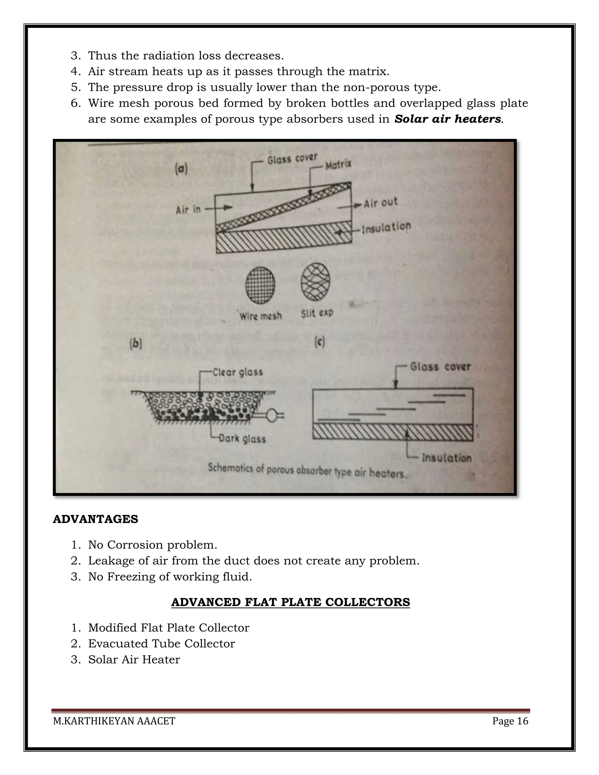
POROUS TYPE SOLAR AIR HEATER
1. The porous type of air heaters has porous absorber which may include slit
and expanded metal, overlapped glass plat absorber and transpired
honeycomb.
2. Solar radiation penetrates to a great depth.](https://image.slidesharecdn.com/lecturenotesfor5units-240420063843-f47c15bb/75/ORO551-RENEWABLE-ENERGY-SOURCES-FULL-NOTES-15-2048.jpg)

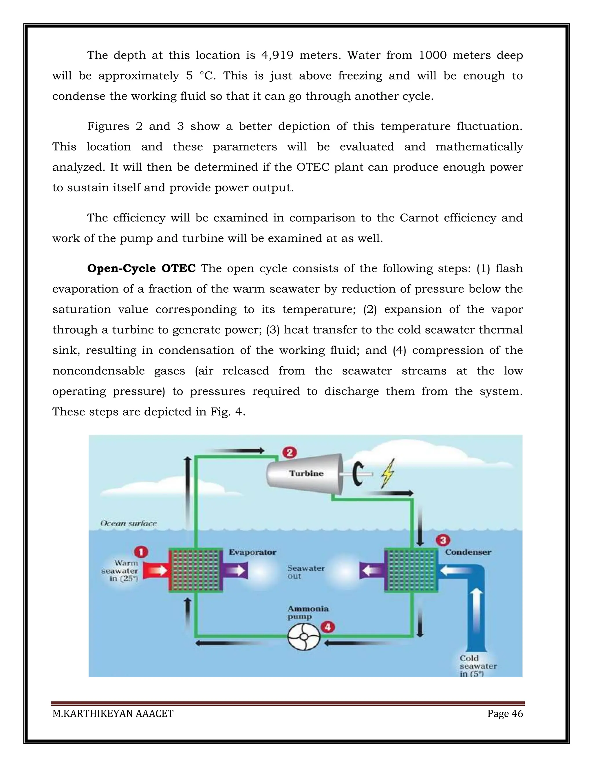
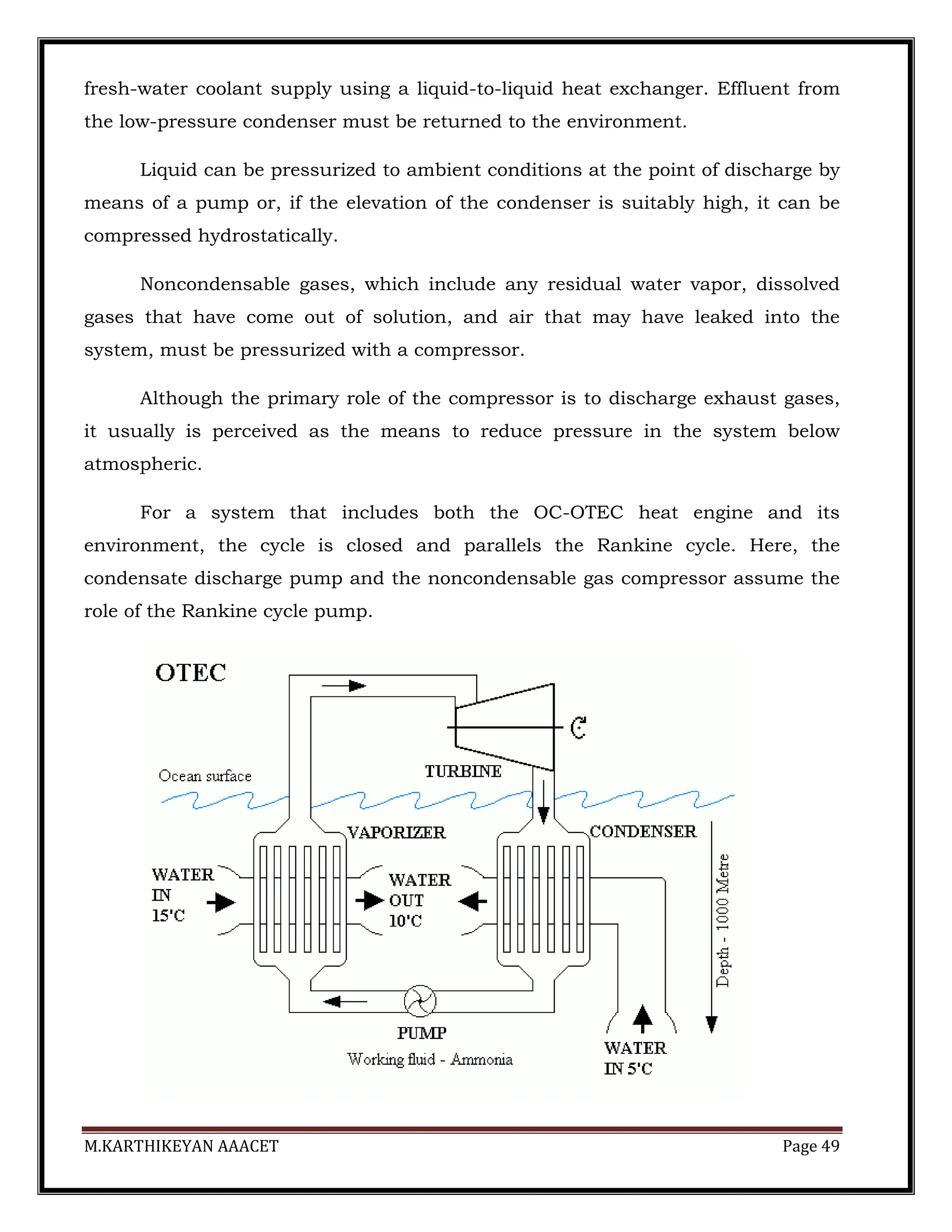
![M.KARTHIKEYAN AAACET Page 47
In the case of a surface condenser, the condensate (desalinated water) must
be compressed to pressures required to discharge it from the power generating
system.
The evaporator, turbine, and condenser operate in partial vacuum ranging
from 3% to 1% atmospheric pressure. This poses a number of practical concerns
that must be addressed.
First, the system must be carefully sealed to prevent in-leakage of
atmospheric air that can severely degrade or shut down operation. Second, the
specific volume of the low-pressure steam is very large compared to that of the
pressurized working fluid used in closed cycle OTEC.
This means that components must have large flow areas to ensure that
steam velocities do not attain excessively high values. Finally, gases such as
oxygen, nitrogen, and carbon dioxide that are dissolved in seawater (essentially
air) come out of solution in a vacuum.
These gases are not condensable and must be exhausted from the system.
In spite of the aforementioned engineering challenges, the Claude cycle enjoys
certain benefits from the selection of water as the working fluid. Water, unlike
ammonia, is nontoxic and environmentally benign.
Moreover, since the evaporator produces desalinated steam, the condenser
can be designed to yield fresh water. In many potential sites in the tropics, potable
water is a highly desired commodity that can be marketed to offset the price of
OTEC-generated electricity.
Flash evaporation is a distinguishing feature of open cycle OTEC. Flash
evaporation involves complex heat and mass transfer processes. In the
configuration tested with the 210 kW OC-OTEC Experimental Apparatus [9, 10]
warm seawater was pumped into a chamber through spouts designed to maximize
the heat-and-mass-transfer surface area by producing a spray of the liquid.](https://image.slidesharecdn.com/lecturenotesfor5units-240420063843-f47c15bb/75/ORO551-RENEWABLE-ENERGY-SOURCES-FULL-NOTES-47-2048.jpg)