Downloaded 33 times

![Chapter 5 Configuration Statements . . . . . . . . . . . . . . . . . . . . . . . . . . . . . . . . . . . . . . . . . 149
[edit protocols isis] Hierarchy Level . . . . . . . . . . . . . . . . . . . . . . . . . . . . . . . . . . . . 149
authentication-key (Protocols IS-IS) . . . . . . . . . . . . . . . . . . . . . . . . . . . . . . . . . . . 152
authentication-key-chain (Protocols IS-IS) . . . . . . . . . . . . . . . . . . . . . . . . . . . . . 153
authentication-type (Protocols IS-IS) . . . . . . . . . . . . . . . . . . . . . . . . . . . . . . . . . . 154
bfd-liveness-detection (Protocols IS-IS) . . . . . . . . . . . . . . . . . . . . . . . . . . . . . . . 155
checksum . . . . . . . . . . . . . . . . . . . . . . . . . . . . . . . . . . . . . . . . . . . . . . . . . . . . . . . . 157
context-identifier . . . . . . . . . . . . . . . . . . . . . . . . . . . . . . . . . . . . . . . . . . . . . . . . . . . 157
clns-routing . . . . . . . . . . . . . . . . . . . . . . . . . . . . . . . . . . . . . . . . . . . . . . . . . . . . . . . 158
csnp-interval . . . . . . . . . . . . . . . . . . . . . . . . . . . . . . . . . . . . . . . . . . . . . . . . . . . . . . 159
disable (Protocols IS-IS) . . . . . . . . . . . . . . . . . . . . . . . . . . . . . . . . . . . . . . . . . . . . 160
disable (LDP Synchronization for IS-IS) . . . . . . . . . . . . . . . . . . . . . . . . . . . . . . . . . 161
export (Protocols IS-IS) . . . . . . . . . . . . . . . . . . . . . . . . . . . . . . . . . . . . . . . . . . . . . 162
external-preference (Protocols IS-IS) . . . . . . . . . . . . . . . . . . . . . . . . . . . . . . . . . . 163
family (Protocols IS-IS) . . . . . . . . . . . . . . . . . . . . . . . . . . . . . . . . . . . . . . . . . . . . . 164
graceful-restart (Protocols IS-IS) . . . . . . . . . . . . . . . . . . . . . . . . . . . . . . . . . . . . . 165
hello-authentication-key . . . . . . . . . . . . . . . . . . . . . . . . . . . . . . . . . . . . . . . . . . . . 166
hello-authentication-key-chain . . . . . . . . . . . . . . . . . . . . . . . . . . . . . . . . . . . . . . . 167
hello-authentication-type . . . . . . . . . . . . . . . . . . . . . . . . . . . . . . . . . . . . . . . . . . . 168
hello-interval (Protocols IS-IS) . . . . . . . . . . . . . . . . . . . . . . . . . . . . . . . . . . . . . . . 169
hello-padding . . . . . . . . . . . . . . . . . . . . . . . . . . . . . . . . . . . . . . . . . . . . . . . . . . . . . 170
hold-time (IS-IS) . . . . . . . . . . . . . . . . . . . . . . . . . . . . . . . . . . . . . . . . . . . . . . . . . . . 172
hold-time (LDP Synchronization for IS-IS) . . . . . . . . . . . . . . . . . . . . . . . . . . . . . . 173
ignore-attached-bit . . . . . . . . . . . . . . . . . . . . . . . . . . . . . . . . . . . . . . . . . . . . . . . . 174
ignore-lsp-metrics (Protocols IS-IS) . . . . . . . . . . . . . . . . . . . . . . . . . . . . . . . . . . . 175
interface (Protocols IS-IS) . . . . . . . . . . . . . . . . . . . . . . . . . . . . . . . . . . . . . . . . . . . 176
ipv4-multicast . . . . . . . . . . . . . . . . . . . . . . . . . . . . . . . . . . . . . . . . . . . . . . . . . . . . . 178
ipv4-multicast-metric . . . . . . . . . . . . . . . . . . . . . . . . . . . . . . . . . . . . . . . . . . . . . . . 178
ipv6-multicast . . . . . . . . . . . . . . . . . . . . . . . . . . . . . . . . . . . . . . . . . . . . . . . . . . . . . 179
ipv6-multicast-metric . . . . . . . . . . . . . . . . . . . . . . . . . . . . . . . . . . . . . . . . . . . . . . . 179
ipv6-unicast . . . . . . . . . . . . . . . . . . . . . . . . . . . . . . . . . . . . . . . . . . . . . . . . . . . . . . 180
ipv6-unicast-metric . . . . . . . . . . . . . . . . . . . . . . . . . . . . . . . . . . . . . . . . . . . . . . . . . 181
isis . . . . . . . . . . . . . . . . . . . . . . . . . . . . . . . . . . . . . . . . . . . . . . . . . . . . . . . . . . . . . . 182
label-switched-path (Protocols IS-IS) . . . . . . . . . . . . . . . . . . . . . . . . . . . . . . . . . 183
LDP-synchronization . . . . . . . . . . . . . . . . . . . . . . . . . . . . . . . . . . . . . . . . . . . . . . . 184
level (Global IS-IS) . . . . . . . . . . . . . . . . . . . . . . . . . . . . . . . . . . . . . . . . . . . . . . . . . 185
level (IS-IS Interfaces) . . . . . . . . . . . . . . . . . . . . . . . . . . . . . . . . . . . . . . . . . . . . . . 186
link-protection (Protocols IS-IS) . . . . . . . . . . . . . . . . . . . . . . . . . . . . . . . . . . . . . . 187
loose-authentication-check . . . . . . . . . . . . . . . . . . . . . . . . . . . . . . . . . . . . . . . . . . 187
lsp-equal-cost . . . . . . . . . . . . . . . . . . . . . . . . . . . . . . . . . . . . . . . . . . . . . . . . . . . . 188
lsp-interval . . . . . . . . . . . . . . . . . . . . . . . . . . . . . . . . . . . . . . . . . . . . . . . . . . . . . . . 189
lsp-lifetime . . . . . . . . . . . . . . . . . . . . . . . . . . . . . . . . . . . . . . . . . . . . . . . . . . . . . . . 190
max-areas . . . . . . . . . . . . . . . . . . . . . . . . . . . . . . . . . . . . . . . . . . . . . . . . . . . . . . . . 191
max-hello-size . . . . . . . . . . . . . . . . . . . . . . . . . . . . . . . . . . . . . . . . . . . . . . . . . . . . 192
max-lsp-size . . . . . . . . . . . . . . . . . . . . . . . . . . . . . . . . . . . . . . . . . . . . . . . . . . . . . . 192
max-snp-size . . . . . . . . . . . . . . . . . . . . . . . . . . . . . . . . . . . . . . . . . . . . . . . . . . . . . 193
mesh-group (Protocols IS-IS) . . . . . . . . . . . . . . . . . . . . . . . . . . . . . . . . . . . . . . . . 194
metric (Protocols IS-IS) . . . . . . . . . . . . . . . . . . . . . . . . . . . . . . . . . . . . . . . . . . . . . 195
multicast-rpf-routes . . . . . . . . . . . . . . . . . . . . . . . . . . . . . . . . . . . . . . . . . . . . . . . . 196
Copyright © 2013, Juniper Networks, Inc.vi
IS-IS Configuration Guide](https://image.slidesharecdn.com/config-guide-routing-is-is-151104131021-lva1-app6891/75/Juniper-MX-Config-guide-routing-is-is-6-2048.jpg)


![configuration into the current candidate configuration. The example does not become
active until you commit the candidate configuration.
If the example configuration contains the top level of the hierarchy (or multiple
hierarchies), the example is a full example. In this case, use the load merge command.
If the example configuration does not start at the top level of the hierarchy, the example
is a snippet. In this case, use the load merge relative command. These procedures are
described in the following sections.
Merging a Full Example
To merge a full example, follow these steps:
1. From the HTML or PDF version of the manual, copy a configuration example into a
text file, save the file with a name, and copy the file to a directory on your routing
platform.
For example, copy the following configuration to a file and name the file ex-script.conf.
Copy the ex-script.conf file to the /var/tmp directory on your routing platform.
system {
scripts {
commit {
file ex-script.xsl;
}
}
}
interfaces {
fxp0 {
disable;
unit 0 {
family inet {
address 10.0.0.1/24;
}
}
}
}
2. Merge the contents of the file into your routing platform configuration by issuing the
load merge configuration mode command:
[edit]
user@host# load merge /var/tmp/ex-script.conf
load complete
Merging a Snippet
To merge a snippet, follow these steps:
1. From the HTML or PDF version of the manual, copy a configuration snippet into a text
file, save the file with a name, and copy the file to a directory on your routing platform.
For example, copy the following snippet to a file and name the file
ex-script-snippet.conf. Copy the ex-script-snippet.conf file to the /var/tmp directory
on your routing platform.
Copyright © 2013, Juniper Networks, Inc.xvi
IS-IS Configuration Guide](https://image.slidesharecdn.com/config-guide-routing-is-is-151104131021-lva1-app6891/75/Juniper-MX-Config-guide-routing-is-is-16-2048.jpg)
![commit {
file ex-script-snippet.xsl; }
2. Move to the hierarchy level that is relevant for this snippet by issuing the following
configuration mode command:
[edit]
user@host# edit system scripts
[edit system scripts]
3. Merge the contents of the file into your routing platform configuration by issuing the
load merge relative configuration mode command:
[edit system scripts]
user@host# load merge relative /var/tmp/ex-script-snippet.conf
load complete
For more information about the load command, see the CLI User Guide.
Documentation Conventions
Table 1 on page xvii defines notice icons used in this guide.
Table 1: Notice Icons
DescriptionMeaningIcon
Indicates important features or instructions.Informational note
Indicates a situation that might result in loss of data or hardware damage.Caution
Alerts you to the risk of personal injury or death.Warning
Alerts you to the risk of personal injury from a laser.Laser warning
Table 2 on page xvii defines the text and syntax conventions used in this guide.
Table 2: Text and Syntax Conventions
ExamplesDescriptionConvention
To enter configuration mode, type
theconfigure command:
user@host> configure
Represents text that you type.Bold text like this
user@host> show chassis alarms
No alarms currently active
Represents output that appears on the
terminal screen.
Fixed-width text like this
xviiCopyright © 2013, Juniper Networks, Inc.
About the Documentation](https://image.slidesharecdn.com/config-guide-routing-is-is-151104131021-lva1-app6891/75/Juniper-MX-Config-guide-routing-is-is-17-2048.jpg)
![Table 2: Text and Syntax Conventions (continued)
ExamplesDescriptionConvention
• A policy term is a named structure
that defines match conditions and
actions.
• Junos OS System Basics Configuration
Guide
• RFC 1997, BGP Communities Attribute
• Introduces or emphasizes important
new terms.
• Identifies book names.
• Identifies RFC and Internet draft titles.
Italic text like this
Configure the machine’s domain name:
[edit]
root@# set system domain-name
domain-name
Represents variables (options for which
you substitute a value) in commands or
configuration statements.
Italic text like this
• To configure a stub area, include the
stub statement at the[edit protocols
ospf area area-id] hierarchy level.
• The console port is labeled CONSOLE.
Represents names of configuration
statements, commands, files, and
directories; configuration hierarchy levels;
or labels on routing platform
components.
Text like this
stub <default-metric metric>;Enclose optional keywords or variables.< > (angle brackets)
broadcast | multicast
(string1 | string2 | string3)
Indicates a choice between the mutually
exclusive keywords or variables on either
side of the symbol. The set of choices is
often enclosed in parentheses for clarity.
| (pipe symbol)
rsvp { # Required for dynamic MPLS onlyIndicates a comment specified on the
same line as the configuration statement
to which it applies.
# (pound sign)
community name members [
community-ids ]
Enclose a variable for which you can
substitute one or more values.
[ ] (square brackets)
[edit]
routing-options {
static {
route default {
nexthop address;
retain;
}
}
}
Identify a level in the configuration
hierarchy.
Indention and braces ( { } )
Identifies a leaf statement at a
configuration hierarchy level.
; (semicolon)
J-Web GUI Conventions
• In the Logical Interfaces box, select
All Interfaces.
• To cancel the configuration, click
Cancel.
Represents J-Web graphical user
interface (GUI) items you click or select.
Bold text like this
In the configuration editor hierarchy,
select Protocols>Ospf.
Separates levels in a hierarchy of J-Web
selections.
> (bold right angle bracket)
Copyright © 2013, Juniper Networks, Inc.xviii
IS-IS Configuration Guide](https://image.slidesharecdn.com/config-guide-routing-is-is-151104131021-lva1-app6891/75/Juniper-MX-Config-guide-routing-is-is-18-2048.jpg)


![IS-IS Terminology
An IS-IS network is a single autonomous system (AS), also called a routing domain, that
consists of end systems and intermediate systems. End systems are network entities that
send and receive packets. Intermediate systems send and receive packets and relay
(forward) packets. (Intermediate system is the Open System Interconnection [OSI] term
for a router.) ISO packets are called network protocol data units (PDUs).
In IS-IS, a single AS can be divided into smaller groups called areas. Routing between
areas is organized hierarchically, allowing a domain to be administratively divided into
smaller areas. This organization is accomplished by configuring Level 1 and Level 2
intermediate systems. Level 1 systems route within an area; when the destination is
outside an area, they route toward a Level 2 system. Level 2 intermediate systems route
between areas and toward other ASs. No IS-IS area functions strictly as a backbone.
Level 1 routers share intra-area routing information, and Level 2 routers share interarea
information about IP addresses available within each area. Uniquely, IS-IS routers can
act as both Level 1 and Level 2 routers, sharing intra-area routes with other Level 1 routers
and interarea routes with other Level 2 routers.
The propagation of link-state updates is determined by the level boundaries. All routers
within a level maintain a complete link-state database of all other routers in the same
level. Each router then uses the Dijkstra algorithm to determine the shortest path from
the local router to other routers in the link-state database.
ISO Network Addresses
IS-IS uses ISO network addresses. Each address identifies a point of connection to the
network, such as a router interface, and is called a network service access point (NSAP).
IS-IS supports multiple NSAP addresses on the loopback (lo0) interface.
An end system can have multiple NSAP addresses, in which case the addresses differ
only by the last byte (called the n-selector). Each NSAP represents a service that is
available at that node. In addition to having multiple services, a single node can belong
to multiple areas.
Each network entity also has a special network address called a network entity title (NET).
Structurally, an NET is identical to an NSAP address but has an n-selector of 00. Most
end systems and intermediate systems have one NET. Intermediate systems that
participate in multiple areas can have multiple NETs.
The following ISO addresses illustrate the IS-IS address format:
49.0001.00a0.c96b.c490.00
49.0001.2081.9716.9018.00
NETs take several forms, depending on your network requirements. NET addresses are
hexadecimal and range from 8 octets to 20 octets in length. Generally, the format consists
of an authority and format Identifier (AFI), a domain ID, an area ID, a system identifier,
and a selector. The simplest format omits the domain ID and is 10 octets long. For
example, the NET address 49.0001.1921.6800.1001.00 consists of the following parts:
Copyright © 2013, Juniper Networks, Inc.4
IS-IS Configuration Guide](https://image.slidesharecdn.com/config-guide-routing-is-is-151104131021-lva1-app6891/75/Juniper-MX-Config-guide-routing-is-is-24-2048.jpg)
![Figure 1: Install Default Route to Nearest Routing Device That Operates
at Both
Level 1 and Level 2
IS-IS Extensions to Support Traffic Engineering
To help provide traffic engineering and MPLS with information about network topology
and loading, extensions have been added to the Junos OS implementation of IS-IS.
Specifically, IS-IS supports new TLVs that specify link attributes. These TLVs are included
in the IS-IS link-state PDUs. The link-attribute information is used to populate the traffic
engineering database, which is used by the Constrained Shortest Path First (CSPF)
algorithm to compute the paths that MPLS LSPs take. This path information is used by
RSVP to set up LSPs and reserve bandwidth for them.
NOTE: Whenever possible, use IS-IS IGP shortcuts instead of traffic
engineering shortcuts.
The traffic engineering extensions are defined in Internet draft draft-isis-traffic-traffic-02,
IS-IS Extensions for Traffic Engineering.
IS-IS IGP Shortcuts
In IS-IS, you can configure shortcuts, which allow IS-IS to use an LSP as the next hop as
if it were a subinterface from the ingress routing device to the egress routing device. The
address specified on the to statement at the [edit protocols mpls label-switched-path
lsp-path-name] hierarchy level must match the router ID of the egress routing device for
the LSP to function as a direct link to the egress routing device and to be used as input
to IS-IS SPF calculations. When used in this way, LSPs are no different than Asynchronous
Transfer Mode (ATM) and Frame Relay virtual circuits (VCs), except that LSPs carry only
IPv4 traffic.
Copyright © 2013, Juniper Networks, Inc.8
IS-IS Configuration Guide](https://image.slidesharecdn.com/config-guide-routing-is-is-151104131021-lva1-app6891/75/Juniper-MX-Config-guide-routing-is-is-28-2048.jpg)


![Overview
In this example, you configure the two IS-IS routing devices in a single area. The devices
have NET addresses 49.0002.0192.0168.0001.00 and 49.0002.0192.0168.0002.00 on
the lo0 interfaces. Additionally, you configure the ISO family on the IS-IS interfaces.
For Junos OS security devices only, you configure the mode packet-based statement at
the [edit security forwarding-options family iso] hierarchy level.
Figure 2 on page 16 shows the topology used in this example.
Figure 2: Simple IS-IS Topology
R1
.1
10.0.0.0/30
.2
R2
lo0:192.168.0.1 lo0:192.168.0.2
g041282
“CLI Quick Configuration” on page 16 shows the configuration for both of the devices in
Figure 2 on page 16. The section “Step-by-Step Procedure” on page 17 describes the
steps on Device R1.
Configuration
CLI Quick
Configuration
To quickly configure this example, copy the following commands, paste them into a text
file, remove any line breaks, change any details necessary to match your network
configuration, and then copy and paste the commands into the CLI at the [edit] hierarchy
level.
Device R1 set security forwarding-options family iso mode packet-based
set interfaces ge-1/2/0 unit 0 description to-R2
set interfaces ge-1/2/0 unit 0 family inet address 10.0.0.1/30
set interfaces ge-1/2/0 unit 0 family iso
set interfaces lo0 unit 0 family inet address 192.168.0.1/32
set interfaces lo0 unit 0 family iso address 49.0002.0192.0168.0001.00
set protocols isis interface ge-1/2/0.0
set protocols isis interface lo0.0
Device R2 set security forwarding-options family iso mode packet-based
set interfaces ge-1/2/0 unit 0 description to-R1
set interfaces ge-1/2/0 unit 0 family inet address 10.0.0.2/30
set interfaces ge-1/2/0 unit 0 family iso
set interfaces lo0 unit 0 family inet address 192.168.0.2/32
set interfaces lo0 unit 0 family iso address 49.0002.0192.0168.0002.00
set protocols isis interface ge-1/2/0.0
set protocols isis interface lo0.0
Copyright © 2013, Juniper Networks, Inc.16
IS-IS Configuration Guide](https://image.slidesharecdn.com/config-guide-routing-is-is-151104131021-lva1-app6891/75/Juniper-MX-Config-guide-routing-is-is-36-2048.jpg)
![Step-by-Step
Procedure
The following example requires you to navigate various levels in the configuration
hierarchy. For instructions on how to do that, see Using the CLI Editor in Configuration
Mode in the CLI User Guide.
To configure IS-IS:
1. Enable IS-IS if your router is in secure context.
[edit security forwarding-options family iso]
user@R1# set mode packet-based
2. Create the interface that connects to Device R2, and configure the ISO family on
the interface.
[edit interfaces ge-1/2/0 unit 0]
user@R1# set description to-R2
user@R1# set family inet address 10.0.0.1/30
user@R1# set family iso
3. Create the loopback interface, set the IP address, and set the NET address.
[edit interfaces lo0 unit 0]
user@R1# set family inet address 192.168.0.1/32
user@R1# set family iso address 49.0002.0192.0168.0001.00
4. Enable IS-IS on the interfaces.
[edit protocols isis]
user@R1# set interface ge-1/2/0.0
user@R1# set interface lo0.0
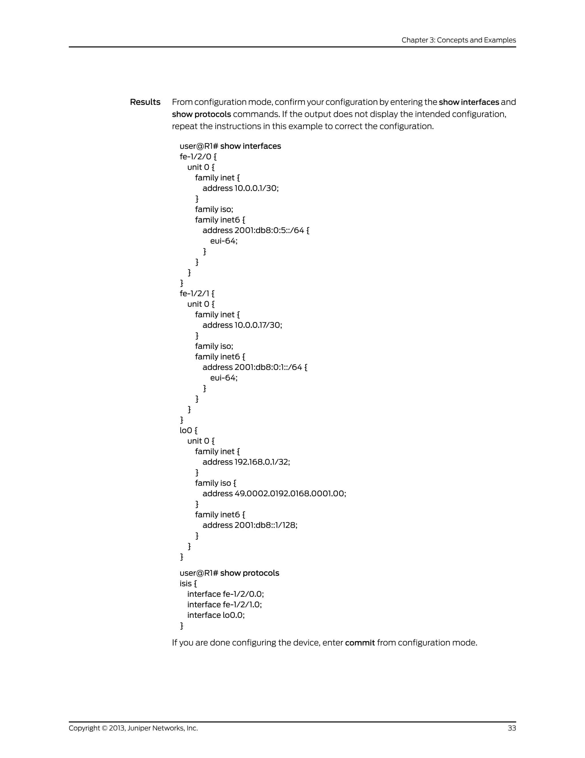
Results From configuration mode, confirm your configuration by entering the show interfaces and
show protocols commands. If the output does not display the intended configuration,
repeat the configuration instructions in this example to correct it.
user@R1# show interfaces
ge-1/2/0 {
unit 0 {
description to-R2;
family inet {
address 10.0.0.1/30;
}
family iso;
}
}
lo0 {
unit 0 {
family inet {
address 192.168.0.1/32;
}
family iso {
address 49.0002.0192.0168.0001.00;
}
}
}
user@R1# show protocols
isis {
17Copyright © 2013, Juniper Networks, Inc.
Chapter 3: Concepts and Examples](https://image.slidesharecdn.com/config-guide-routing-is-is-151104131021-lva1-app6891/75/Juniper-MX-Config-guide-routing-is-is-37-2048.jpg)
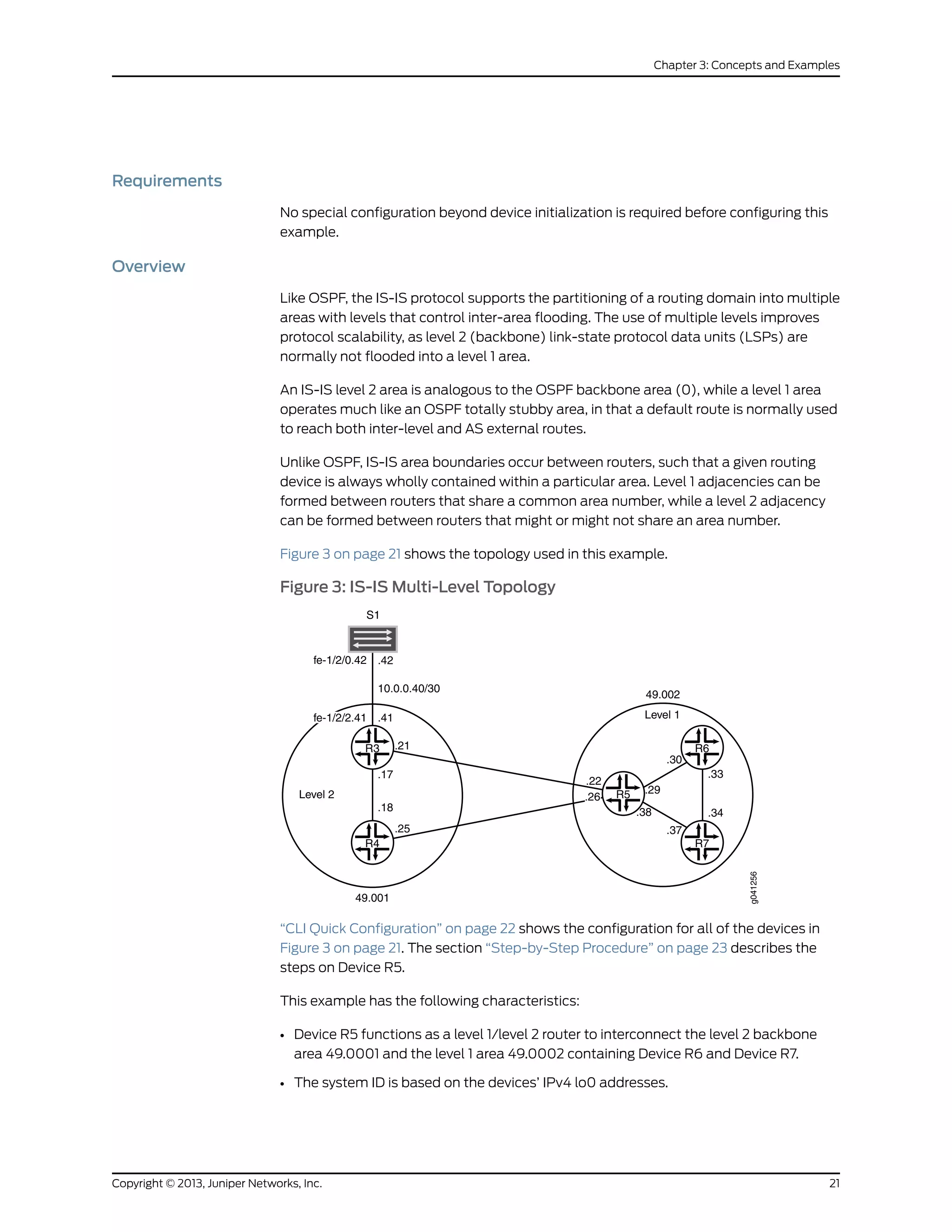
![• Loss of any individual interface does not totally disrupt the IS-IS operation.
• The IPv4 lo0 addresses of all routers are reachable through IS-IS.
• The link between Device R3 and Device S1 appears in area 49.0001 as an intra-area
route. No IS-IS adjacencies can be established on this interface. This is accomplished
by configuring the passive statement on Device R3’s interface to Device S1.
• The loopback addresses of level 2 devices do not appear in a level 1 area.
• There is only one adjacency for each device pairing.
Configuration
CLI Quick
Configuration
To quickly configure this example, copy the following commands, paste them into a text
file, remove any line breaks, change any details necessary to match your network
configuration, and then copy and paste the commands into the CLI at the [edit] hierarchy
level.
Device R3 set interfaces fe-1/2/0 unit 17 description to-R4
set interfaces fe-1/2/0 unit 17 family inet address 10.0.0.17/30
set interfaces fe-1/2/0 unit 17 family iso
set interfaces fe-1/2/1 unit 21 description to-R5
set interfaces fe-1/2/1 unit 21 family inet address 10.0.0.21/30
set interfaces fe-1/2/1 unit 21 family iso
set interfaces fe-1/2/2 unit 41 family inet address 10.0.0.41/30
set interfaces fe-1/2/2 unit 41 description to-S1
set interfaces lo0 unit 3 family inet address 192.168.0.3/32
set interfaces lo0 unit 3 family iso address 49.0001.0192.0168.0003.00
set protocols isis interface fe-1/2/0.17 level 1 disable
set protocols isis interface fe-1/2/1.21 level 1 disable
set protocols isis interface lo0.3 level 1 disable
set protocols isis interface fe-1/2/2.41 passive
Device R4 set interfaces fe-1/2/0 unit 18 description to-R3
set interfaces fe-1/2/0 unit 18 family inet address 10.0.0.18/30
set interfaces fe-1/2/0 unit 18 family iso
set interfaces fe-1/2/1 unit 25 description to-R5
set interfaces fe-1/2/1 unit 25 family inet address 10.0.0.25/30
set interfaces fe-1/2/1 unit 25 family iso
set interfaces lo0 unit 4 family inet address 192.168.0.4/32
set interfaces lo0 unit 4 family iso address 49.0001.0192.0168.0004.00
set protocols isis interface fe-1/2/0.18 level 1 disable
set protocols isis interface fe-1/2/1.25 level 1 disable
set protocols isis interface lo0.4 level 1 disable
Device R5 set interfaces fe-1/2/0 unit 22 description to-R3
set interfaces fe-1/2/0 unit 22 family inet address 10.0.0.22/30
set interfaces fe-1/2/0 unit 22 family iso
set interfaces fe-1/2/1 unit 26 description to-R4
set interfaces fe-1/2/1 unit 26 family inet address 10.0.0.26/30
set interfaces fe-1/2/1 unit 26 family iso
set interfaces fe-1/2/2 unit 29 description to-R6
set interfaces fe-1/2/2 unit 29 family inet address 10.0.0.29/30
set interfaces fe-1/2/2 unit 29 family iso
set interfaces fe-1/2/3 unit 38 description to-R7
Copyright © 2013, Juniper Networks, Inc.22
IS-IS Configuration Guide](https://image.slidesharecdn.com/config-guide-routing-is-is-151104131021-lva1-app6891/75/Juniper-MX-Config-guide-routing-is-is-42-2048.jpg)
![set interfaces fe-1/2/3 unit 38 family inet address 10.0.0.38/30
set interfaces fe-1/2/3 unit 38 family iso
set interfaces lo0 unit 5 family inet address 192.168.0.5/32
set interfaces lo0 unit 5 family iso address 49.0002.0192.0168.0005.00
set protocols isis interface fe-1/2/0.22 level 1 disable
set protocols isis interface fe-1/2/0.26 level 1 disable
set protocols isis interface fe-1/2/0.29 level 2 disable
set protocols isis interface fe-1/2/3.38 level 2 disable
set protocols isis interface lo0.5 level 1 disable
Device R6 set interfaces fe-1/2/0 unit 30 description to-R5
set interfaces fe-1/2/0 unit 30 family inet address 10.0.0.30/30
set interfaces fe-1/2/0 unit 30 family iso
set interfaces fe-1/2/1 unit 33 description to-R7
set interfaces fe-1/2/1 unit 33 family inet address 10.0.0.33/30
set interfaces fe-1/2/1 unit 33 family iso
set interfaces lo0 unit 6 family inet address 192.168.0.6/32
set interfaces lo0 unit 6 family iso address 49.0002.0192.0168.0006.00
set protocols isis interface fe-1/2/0.30 level 2 disable
set protocols isis interface fe-1/2/1.33 level 2 disable
set protocols isis interface lo0.6 level 2 disable
Device R7 set interfaces fe-1/2/0 unit 34 description to-R6
set interfaces fe-1/2/0 unit 34 family inet address 10.0.0.34/30
set interfaces fe-1/2/0 unit 34 family iso
set interfaces fe-1/2/1 unit 37 description to-R5
set interfaces fe-1/2/1 unit 37 family inet address 10.0.0.37/30
set interfaces fe-1/2/1 unit 37 family iso
set interfaces lo0 unit 7 family inet address 192.168.0.7/32
set interfaces lo0 unit 7 family iso address 49.0002.0192.0168.0007.00
set protocols isis interface fe-1/2/0.34 level 2 disable
set protocols isis interface fe-1/2/1.37 level 2 disable
set protocols isis interface lo0.7 level 2 disable
Device S1 set interfaces fe-1/2/0 unit 42 family inet address 10.0.0.42/30
set interfaces fe-1/2/0 unit 42 description to-R3
Step-by-Step
Procedure
The following example requires you to navigate various levels in the configuration
hierarchy. For information about navigating the CLI, see Using the CLI Editor in
Configuration Mode in the CLI User Guide.
To configure multi-level IS-IS:
1. Configure the network interfaces.
Enable IS-IS on the interfaces by Including the ISO address family on each interface.
[edit interfaces]
user@R5# set fe-1/2/0 unit 22 description to-R3
user@R5# set fe-1/2/0 unit 22 family inet address 10.0.0.22/30
user@R5# set fe-1/2/0 unit 22 family iso
user@R5# set fe-1/2/1 unit 26 description to-R4
user@R5# set fe-1/2/1 unit 26 family inet address 10.0.0.26/30
user@R5# set fe-1/2/1 unit 26 family iso
23Copyright © 2013, Juniper Networks, Inc.
Chapter 3: Concepts and Examples](https://image.slidesharecdn.com/config-guide-routing-is-is-151104131021-lva1-app6891/75/Juniper-MX-Config-guide-routing-is-is-43-2048.jpg)
![user@R5# set fe-1/2/2 unit 29 description to-R6
user@R5# set fe-1/2/2 unit 29 family inet address 10.0.0.29/30
user@R5# set fe-1/2/2 unit 29 family iso
user@R5# set fe-1/2/3 unit 38 description to-R7
user@R5# set fe-1/2/3 unit 38 family inet address 10.0.0.38/30
user@R5# set fe-1/2/3 unit 38 family iso
2. Configure two loopback interface addresses.
One address is for IPv4.
The other is for the IS-IS area 49.0002 so that Device R5 can form adjacencies with
the other level 1 devices in area 49.0002. Even though Device R5’s NET identifies
itself as belonging to the level 1 area 49.0002, its loopback interface is not configured
as a level 1 interface. Doing so would cause the route to Device R5’s loopback to be
injected into the level 1 area.
[edit interfaces lo0 unit 5]
user@R5# set family inet address 192.168.0.5/32
user@R5# set family iso address 49.0002.0192.0168.0005.00
3. Specify the IS-IS level on a per-interface basis.
Device R5 becomes adjacent to the other routing devices on the same level on each
link.
By default, IS-IS is enabled for IS-IS areas on all interfaces on which the ISO protocol
family is enabled (at the [edit interfaces interface-name unit logical-unit-number]
hierarchy level). To disable IS-IS at any particular level on an interface, include the
disable statement.
Device R5’s loopback interface is configured to run level 2 only. If level 1 operation
were enabled on lo0.5, Device R5 would include its loopback address in its level 1
LSP, which is incorrect for this example in which the loopback addresses of level 2
devices must not appear in a level 1 area.
Unlike OSPF, you must explicitly list the router’s lo0 interface at the [edit protocols
isis] hierarchy level, because this interface is the source of the router’s NET, and
therefore must be configured as an IS-IS interface. In IS-IS, the lo0 interface operates
in the passive mode by default, which is ideal because adjacency formation can
never occur on a virtual interface.
[edit protocols isis]
user@R5# set interface fe-1/2/0.22 level 1 disable
user@R5# set interface fe-1/2/0.26 level 1 disable
user@R5# set interface fe-1/2/0.29 level 2 disable
user@R5# set interface fe-1/2/3.38 level 2 disable
user@R5# set interface lo0.5 level 1 disable
Results From configuration mode, confirm your configuration by entering the show interfaces and
show protocols commands. If the output does not display the intended configuration,
repeat the configuration instructions in this example to correct it.
user@R5# show interfaces
fe-1/2/0 {
Copyright © 2013, Juniper Networks, Inc.24
IS-IS Configuration Guide](https://image.slidesharecdn.com/config-guide-routing-is-is-151104131021-lva1-app6891/75/Juniper-MX-Config-guide-routing-is-is-44-2048.jpg)
![Unlike RIP and OSPF, IS-IS does not require a distinct protocol or a new version to support
IPv6. Because IS-IS uses ISO addresses, the configuration for IPv6 and IPv4 is identical
in the Junos OS implementation of IS-IS. For IS-IS to carry IPv6 routes, you only need to
add IPv6 addresses to IS-IS enabled interfaces or include other IPv6 routes in your IS-IS
export policy.
The only explicit configuration needed in IS-IS with regard to IPv6 is if you want to disable
it. Alternatively, you can disable IPv4 routing and use IS-IS with IPv6 only. An example
of each is provided here:
Disable IPv6 routing in IS-IS:
[edit protocols isis]
user@host# set no-ipv6-routing
Use IS-IS exclusively for IPv6 routing:
[edit protocols isis]
user@host# set no-ipv4-routing
Figure 4 on page 31 shows the topology used in this example.
Figure 4: IS-IS IPv4 and IPv6 Dual Stacking Topology
R3R2
R1
g041305
fe-1/2/0 .2
fe-1/2/0
.1
10.0.0.0/30
fe-1/2/1
2001:db8:0:1::/64
2001:db8:0:5::/64
.17
10.0.0.16/30
.18
fe-1/2/0
IPv4
IPv6
“CLI Quick Configuration” on page 31 shows the configuration for all of the devices in
Figure 4 on page 31. The section “Step-by-Step Procedure” on page 32 describes the
steps on Device R1.
Configuration
CLI Quick
Configuration
To quickly configure this example, copy the following commands, paste them into a text
file, remove any line breaks, change any details necessary to match your network
configuration, and then copy and paste the commands into the CLI at the [edit] hierarchy
level.
Device R1 set interfaces fe-1/2/0 unit 0 family inet address 10.0.0.1/30
set interfaces fe-1/2/0 unit 0 family iso
set interfaces fe-1/2/0 unit 0 family inet6 address 2001:db8:0:5::/64 eui-64
set interfaces fe-1/2/1 unit 0 family inet address 10.0.0.17/30
set interfaces fe-1/2/1 unit 0 family iso
set interfaces fe-1/2/1 unit 0 family inet6 address 2001:db8:0:1::/64 eui-64
set interfaces lo0 unit 0 family inet address 192.168.0.1/32
31Copyright © 2013, Juniper Networks, Inc.
Chapter 3: Concepts and Examples](https://image.slidesharecdn.com/config-guide-routing-is-is-151104131021-lva1-app6891/75/Juniper-MX-Config-guide-routing-is-is-51-2048.jpg)
![set interfaces lo0 unit 0 family iso address 49.0002.0192.0168.0001.00
set interfaces lo0 unit 0 family inet6 address 2001:db8::1/128
set protocols isis interface fe-1/2/0.0
set protocols isis interface fe-1/2/1.0
set protocols isis interface lo0.0
Device R2 set interfaces fe-1/2/0 unit 0 family inet address 10.0.0.2/30
set interfaces fe-1/2/0 unit 0 family iso
set interfaces fe-1/2/0 unit 0 family inet6 address 2001:db8:0:5::/64 eui-64
set interfaces lo0 unit 0 family inet address 192.168.0.2/32
set interfaces lo0 unit 0 family iso address 49.0002.0192.0168.0002.00
set interfaces lo0 unit 0 family inet6 address 2001:db8::2/128
set protocols isis interface fe-1/2/0.0
set protocols isis interface lo0.0
Device R3 set interfaces fe-1/2/0 unit 0 family inet address 10.0.0.18/30
set interfaces fe-1/2/0 unit 0 family iso
set interfaces fe-1/2/0 unit 0 family inet6 address 2001:db8:0:1::/64 eui-64
set interfaces lo0 unit 0 family inet address 192.168.0.3/32
set interfaces lo0 unit 0 family iso address 49.0002.0192.0168.0003.00
set interfaces lo0 unit 0 family inet6 address 2001:db8::3/128
set protocols isis interface fe-1/2/0.0
set protocols isis interface lo0.0
Step-by-Step
Procedure
The following example requires you to navigate various levels in the configuration
hierarchy. For information about navigating the CLI, see Using the CLI Editor in
Configuration Mode in the Junos OS CLI User Guide.
To configure IS-IS dual stacking:
1. Configure the interfaces, including both IPv4 and IPv6 addresses on each interface.
Optionally, include the eui-64 statement to automatically generate the host number
portion of interface addresses.
[edit interfaces]
user@R1# set fe-1/2/0 unit 0 family inet address 10.0.0.1/30
user@R1# set fe-1/2/0 unit 0 family iso
user@R1# set fe-1/2/0 unit 0 family inet6 address 2001:db8:0:5::/64 eui-64
user@R1# set fe-1/2/1 unit 0 family inet address 10.0.0.17/30
user@R1# set fe-1/2/1 unit 0 family iso
user@R1# set fe-1/2/1 unit 0 family inet6 address 2001:db8:0:1::/64 eui-64
user@R1# set lo0 unit 0 family inet address 192.168.0.1/32
user@R1# set lo0 unit 0 family iso address 49.0002.0192.0168.0001.00
user@R1# set lo0 unit 0 family inet6 address 2001:db8::1/128
2. Enable IS-IS on the interfaces.
[edit protocols isis]
user@R1# set interface fe-1/2/0.0
user@R1# set interface fe-1/2/1.0
user@R1# set interface lo0.0
Copyright © 2013, Juniper Networks, Inc.32
IS-IS Configuration Guide](https://image.slidesharecdn.com/config-guide-routing-is-is-151104131021-lva1-app6891/75/Juniper-MX-Config-guide-routing-is-is-52-2048.jpg)
![Action user@R1> show route table inet6.0
inet6.0: 11 destinations, 12 routes (11 active, 0 holddown, 0 hidden)
+ = Active Route, - = Last Active, * = Both
2001:db8::1/128 *[Direct/0] 18:52:52
> via lo0.0
2001:db8::2/128 *[IS-IS/15] 01:59:52, metric 10
> to fe80::2a0:a514:0:24c via fe-1/2/0.0
2001:db8::3/128 *[IS-IS/15] 01:59:52, metric 10
> to fe80::2a0:a514:0:124c via fe-1/2/1.0
2001:db8:0:1::/64 *[Direct/0] 18:52:15
> via fe-1/2/1.0
2001:db8:0:1:2a0:a514:0:114c/128
*[Local/0] 18:52:48
Local via fe-1/2/1.0
2001:db8:0:5::/64 *[Direct/0] 18:52:49
> via fe-1/2/0.0
2001:db8:0:5:2a0:a514:0:14c/128
*[Local/0] 18:52:49
Local via fe-1/2/0.0
fe80::/64 *[Direct/0] 18:52:49
> via fe-1/2/0.0
[Direct/0] 18:52:15
> via fe-1/2/1.0
fe80::2a0:a50f:fc56:14c/128
*[Direct/0] 18:52:52
> via lo0.0
fe80::2a0:a514:0:14c/128
*[Local/0] 18:52:49
Local via fe-1/2/0.0
fe80::2a0:a514:0:114c/128
*[Local/0] 18:52:48
Local via fe-1/2/1.0
Meaning The output shows the IPv6 interface routes (direct and local) and the IPv6 routes learned
through IS-IS.
Related
Documentation
Example: Configuring IS-IS•
Example: Configuring IS-IS on Logical Systems Within the Same Router
This example shows how to configure an IS-IS network by using multiple logical systems
that are running on a single physical router. The logical systems are connected by logical
tunnel interfaces.
• Requirements on page 36
• Overview on page 37
• Configuration on page 37
• Verification on page 42
Requirements
You must connect the logical systems by using logical tunnel (lt) interfaces. See Example:
Connecting Logical Systems Within the Same Router Using Logical Tunnel Interfaces.
Copyright © 2013, Juniper Networks, Inc.36
IS-IS Configuration Guide](https://image.slidesharecdn.com/config-guide-routing-is-is-151104131021-lva1-app6891/75/Juniper-MX-Config-guide-routing-is-is-56-2048.jpg)
![Overview
This example shows an IS-IS configuration with three logical systems running on one
physical router. Each logical system has its own routing table. The configuration enables
the protocol on all logical tunnel interfaces that participate in the IS-IS domain.
Figure 5 on page 37 shows the sample network.
Figure 5: IS-IS on Logical Systems
Configuration
CLI Quick
Configuration
To quickly configure this example, copy the following commands, paste them into a text
file, remove any line breaks, change any details necessary to match your network
configuration, and then copy and paste the commands into the CLI at the [edit] hierarchy
level.
set logical-systems LS1 interfaces lt-0/1/0 unit 2 description LS1->LS2
set logical-systems LS1 interfaces lt-0/1/0 unit 2 encapsulation ethernet
set logical-systems LS1 interfaces lt-0/1/0 unit 2 peer-unit 1
set logical-systems LS1 interfaces lt-0/1/0 unit 2 family inet address 10.0.0.1/30
set logical-systems LS1 interfaces lt-0/1/0 unit 2 family iso
set logical-systems LS1 interfaces lt-0/1/0 unit 0 description LS1->LS3
set logical-systems LS1 interfaces lt-0/1/0 unit 0 encapsulation ethernet
set logical-systems LS1 interfaces lt-0/1/0 unit 0 peer-unit 5
set logical-systems LS1 interfaces lt-0/1/0 unit 0 family inet address 10.0.1.2/30
set logical-systems LS1 interfaces lt-0/1/0 unit 0 family iso
set logical-systems LS1 interfaces lo0 unit 1 family iso address 49.0001.1720.1600.1001.00
set logical-systems LS1 protocols isis interface lt-0/1/0.0
set logical-systems LS1 protocols isis interface lt-0/1/0.2
set logical-systems LS1 protocols isis interface lo0.1 passive
set logical-systems LS2 interfaces lt-0/1/0 unit 1 description LS2->LS1
37Copyright © 2013, Juniper Networks, Inc.
Chapter 3: Concepts and Examples](https://image.slidesharecdn.com/config-guide-routing-is-is-151104131021-lva1-app6891/75/Juniper-MX-Config-guide-routing-is-is-57-2048.jpg)
![set logical-systems LS2 interfaces lt-0/1/0 unit 1 encapsulation ethernet
set logical-systems LS2 interfaces lt-0/1/0 unit 1 peer-unit 2
set logical-systems LS2 interfaces lt-0/1/0 unit 1 family inet address 10.0.0.2/30
set logical-systems LS2 interfaces lt-0/1/0 unit 1 family iso
set logical-systems LS2 interfaces lt-0/1/0 unit 4 description LS2->LS3
set logical-systems LS2 interfaces lt-0/1/0 unit 4 encapsulation ethernet
set logical-systems LS2 interfaces lt-0/1/0 unit 4 peer-unit 3
set logical-systems LS2 interfaces lt-0/1/0 unit 4 family inet address 10.0.2.2/30
set logical-systems LS2 interfaces lt-0/1/0 unit 4 family iso
set logical-systems LS2 interfaces lo0 unit 2 family iso address
49.0001.1720.1600.2002.00
set logical-systems LS2 protocols isis interface lt-0/1/0.1
set logical-systems LS2 protocols isis interface lt-0/1/0.4
set logical-systems LS2 protocols isis interface lo0.2 passive
set logical-systems LS3 interfaces lt-0/1/0 unit 3 description LS3->LS2
set logical-systems LS3 interfaces lt-0/1/0 unit 3 encapsulation ethernet
set logical-systems LS3 interfaces lt-0/1/0 unit 3 peer-unit 4
set logical-systems LS3 interfaces lt-0/1/0 unit 3 family inet address 10.0.2.1/30
set logical-systems LS3 interfaces lt-0/1/0 unit 3 family iso
set logical-systems LS3 interfaces lt-0/1/0 unit 5 description LS3->LS1
set logical-systems LS3 interfaces lt-0/1/0 unit 5 encapsulation ethernet
set logical-systems LS3 interfaces lt-0/1/0 unit 5 peer-unit 0
set logical-systems LS3 interfaces lt-0/1/0 unit 5 family inet address 10.0.1.1/30
set logical-systems LS3 interfaces lt-0/1/0 unit 5 family iso
setlogical-systemsLS3interfaceslo0unit3familyisoaddress49.0001.1234.1600.2231.00
set logical-systems LS3 protocols isis interface lt-0/1/0.5
set logical-systems LS3 protocols isis interface lt-0/1/0.3
set logical-systems LS3 protocols isis interface lo0.3 passive
Step-by-Step
Procedure
The following example requires you to navigate various levels in the configuration
hierarchy. For information about navigating the CLI, see Using the CLI Editor in
Configuration Mode in the CLI User Guide.
To configure IS-IS on logical systems:
1. Configure the logical tunnel interface on Logical System LS1 connecting to Logical
System LS2.
[edit logical-systems LS1]
user@host# set interfaces lt-0/1/0 unit 2 description LS1->LS2
user@host# set interfaces lt-0/1/0 unit 2 encapsulation ethernet
user@host# set interfaces lt-0/1/0 unit 2 peer-unit 1
user@host# set interfaces lt-0/1/0 unit 2 family inet address 10.0.0.1/30
user@host# set interfaces lt-0/1/0 unit 2 family iso
2. Configure the logical tunnel interface on Logical System LS1 connecting to Logical
System LS3.
[edit logical-systems LS1]
user@host# set interfaces lt-0/1/0 unit 0 description LS1->LS3
user@host# set interfaces lt-0/1/0 unit 0 encapsulation ethernet
user@host# set interfaces lt-0/1/0 unit 0 peer-unit 5
user@host# set interfaces lt-0/1/0 unit 0 family inet address 10.0.1.2/30
user@host# set interfaces lt-0/1/0 unit 0 family iso
Copyright © 2013, Juniper Networks, Inc.38
IS-IS Configuration Guide](https://image.slidesharecdn.com/config-guide-routing-is-is-151104131021-lva1-app6891/75/Juniper-MX-Config-guide-routing-is-is-58-2048.jpg)
![3. Configure the logical tunnel interface on Logical System LS2 connecting to Logical
System LS1.
[edit logical-systems LS2]
user@host# set interfaces lt-0/1/0 unit 1 description LS2->LS1
user@host# set interfaces lt-0/1/0 unit 1 encapsulation ethernet
user@host# set interfaces lt-0/1/0 unit 1 peer-unit 2
user@host# set interfaces lt-0/1/0 unit 1 family inet address 10.0.0.2/30
user@host# set interfaces lt-0/1/0 unit 1 family iso
4. Configure the logical tunnel interface on Logical System LS2 connecting to Logical
System LS3.
[edit logical-systems LS2]
user@host# set interfaces lt-0/1/0 unit 4 description LS2->LS3
user@host# set interfaces lt-0/1/0 unit 4 encapsulation ethernet
user@host# set interfaces lt-0/1/0 unit 4 peer-unit 3
user@host# set interfaces lt-0/1/0 unit 4 family inet address 10.0.2.2/30
user@host# set interfaces lt-0/1/0 unit 4 family iso
5. Configure the logical tunnel interface on Logical System LS3 connecting to Logical
System LS2.
[edit logical-systems LS3]
user@host# set interfaces lt-0/1/0 unit 3 description LS3->LS2
user@host# set interfaces lt-0/1/0 unit 3 encapsulation ethernet
user@host# set interfaces lt-0/1/0 unit 3 peer-unit 4
user@host# set interfaces lt-0/1/0 unit 3 family inet address 10.0.2.1/30
user@host# set interfaces lt-0/1/0 unit 3 family iso
6. Configure the logical tunnel interface on Logical System LS3 connecting to Logical
System LS1.
[edit logical-systems LS3]
user@host# set interfaces lt-0/1/0 unit 5 description LS3->LS1
user@host# set interfaces lt-0/1/0 unit 5 encapsulation ethernet
user@host# set interfaces lt-0/1/0 unit 5 peer-unit 0
user@host# set interfaces lt-0/1/0 unit 5 family inet address 10.0.1.1/30
user@host# set interfaces lt-0/1/0 unit 5 family iso
7. Configure the ISO address on the loopback interface for the three logical systems.
[edit logical-systems LS1]
user@host# set interfaces lo0 unit 1 family iso address 49.0001.1720.1600.1001.00
user@host# set protocols isis interface lo0.1 passive
[edit logical-systems LS2]
user@host# setinterfaceslo0unit2familyisoaddress49.0001.1720.1600.2002.00
user@host# set protocols isis interface lo0.2 passive
[edit logical-systems LS3]
user@host# set interfaces lo0 unit 3 family iso address 49.0001.1234.1600.2231.00
user@host# set protocols isis interface lo0.3 passive
8. Configure IS-IS on all the interfaces.
[edit logical-systems LS1 protocols isis]
user@host# set interface lt-0/1/0.0
user@host# set interface lt-0/1/0.2
[edit logical-systems LS2 protocols isis]
39Copyright © 2013, Juniper Networks, Inc.
Chapter 3: Concepts and Examples](https://image.slidesharecdn.com/config-guide-routing-is-is-151104131021-lva1-app6891/75/Juniper-MX-Config-guide-routing-is-is-59-2048.jpg)
![user@host# set interface lt-0/1/0.1
user@host# set interface lt-0/1/0.4
[edit logical-systems LS3 protocols isis]
user@host# set interface lt-0/1/0.5
user@host# set interface lt-0/1/0.3
9. If you are done configuring the device, commit the configuration.
[edit]
user@host# commit
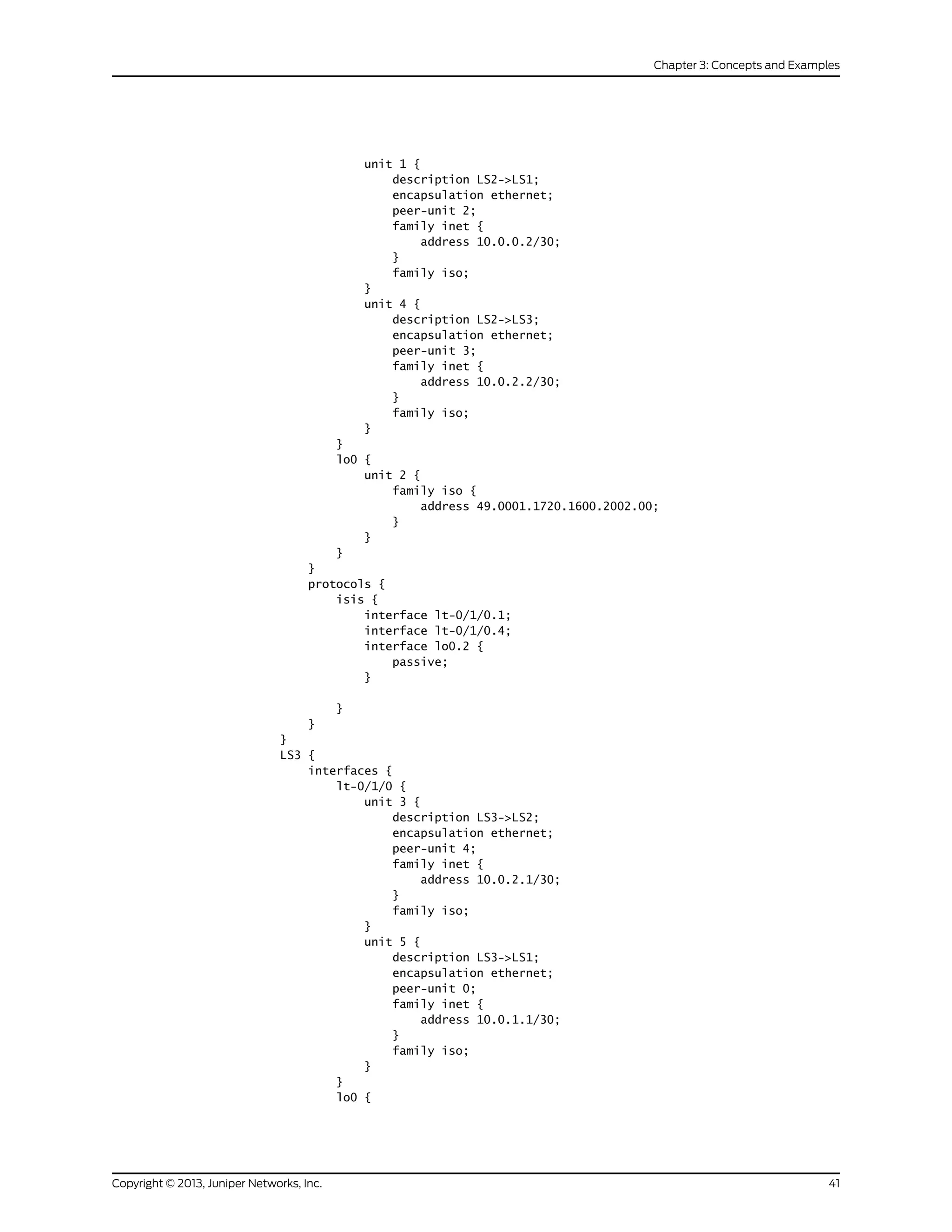
Results
Confirm your configuration by issuing the show logical-systems command.
user@host# show logical-systems
LS1 {
interfaces {
lt-0/1/0 {
unit 0 {
description LS1->LS3;
encapsulation ethernet;
peer-unit 5;
family inet {
address 10.0.1.2/30;
}
family iso;
}
unit 2 {
description LS1->LS2;
encapsulation ethernet;
peer-unit 1;
family inet {
address 10.0.0.1/30;
}
family iso;
}
}
lo0 {
unit 1 {
family iso {
address 49.0001.1720.1600.1001.00;
}
}
}
}
protocols {
isis {
interface lt-0/1/0.0;
interface lt-0/1/0.2;
interface lo0.1 {
passive;
}
}
}
}
LS2 {
interfaces {
lt-0/1/0 {
Copyright © 2013, Juniper Networks, Inc.40
IS-IS Configuration Guide](https://image.slidesharecdn.com/config-guide-routing-is-is-151104131021-lva1-app6891/75/Juniper-MX-Config-guide-routing-is-is-60-2048.jpg)
![Action user@host> show route logical-system LS1
inet.0: 5 destinations, 5 routes (5 active, 0 holddown, 0 hidden)
+ = Active Route, - = Last Active, * = Both
10.0.0.0/30 *[Direct/0] 3w0d 01:37:52
> via lt-0/1/0.2
10.0.0.1/32 *[Local/0] 3w0d 01:37:52
Local via lt-0/1/0.2
10.0.1.0/30 *[Direct/0] 3w0d 01:37:52
> via lt-0/1/0.0
10.0.1.2/32 *[Local/0] 3w0d 01:37:52
Local via lt-0/1/0.0
10.0.2.0/30 *[IS-IS/15] 3w0d 01:37:13, metric 20
> to 10.0.1.1 via lt-0/1/0.0
to 10.0.0.2 via lt-0/1/0.2
iso.0: 1 destinations, 1 routes (1 active, 0 holddown, 0 hidden)
+ = Active Route, - = Last Active, * = Both
49.0001.1720.1600.1001/72
*[Direct/0] 3w0d 01:37:52
> via lo0.1
user@host> show route logical-system LS2
inet.0: 5 destinations, 5 routes (5 active, 0 holddown, 0 hidden)
+ = Active Route, - = Last Active, * = Both
10.0.0.0/30 *[Direct/0] 3w0d 01:38:01
> via lt-0/1/0.1
10.0.0.2/32 *[Local/0] 3w0d 01:38:01
Local via lt-0/1/0.1
10.0.1.0/30 *[IS-IS/15] 3w0d 01:37:01, metric 20
to 10.0.0.1 via lt-0/1/0.1
> to 10.0.2.1 via lt-0/1/0.4
10.0.2.0/30 *[Direct/0] 3w0d 01:38:01
> via lt-0/1/0.4
10.0.2.2/32 *[Local/0] 3w0d 01:38:01
Local via lt-0/1/0.4
iso.0: 1 destinations, 1 routes (1 active, 0 holddown, 0 hidden)
+ = Active Route, - = Last Active, * = Both
49.0001.1720.1600.2002/72
*[Direct/0] 3w0d 01:38:01
> via lo0.2
user@host> show route logical-system LS3
inet.0: 5 destinations, 5 routes (5 active, 0 holddown, 0 hidden)
+ = Active Route, - = Last Active, * = Both
10.0.0.0/30 *[IS-IS/15] 3w0d 01:37:10, metric 20
to 10.0.2.2 via lt-0/1/0.3
> to 10.0.1.2 via lt-0/1/0.5
10.0.1.0/30 *[Direct/0] 3w0d 01:38:10
> via lt-0/1/0.5
10.0.1.1/32 *[Local/0] 3w0d 01:38:11
Local via lt-0/1/0.5
10.0.2.0/30 *[Direct/0] 3w0d 01:38:11
> via lt-0/1/0.3
10.0.2.1/32 *[Local/0] 3w0d 01:38:11
43Copyright © 2013, Juniper Networks, Inc.
Chapter 3: Concepts and Examples](https://image.slidesharecdn.com/config-guide-routing-is-is-151104131021-lva1-app6891/75/Juniper-MX-Config-guide-routing-is-is-63-2048.jpg)
![Local via lt-0/1/0.3
iso.0: 1 destinations, 1 routes (1 active, 0 holddown, 0 hidden)
+ = Active Route, - = Last Active, * = Both
49.0001.1234.1600.2231/72
*[Direct/0] 3w0d 01:38:11
> via lo0.3
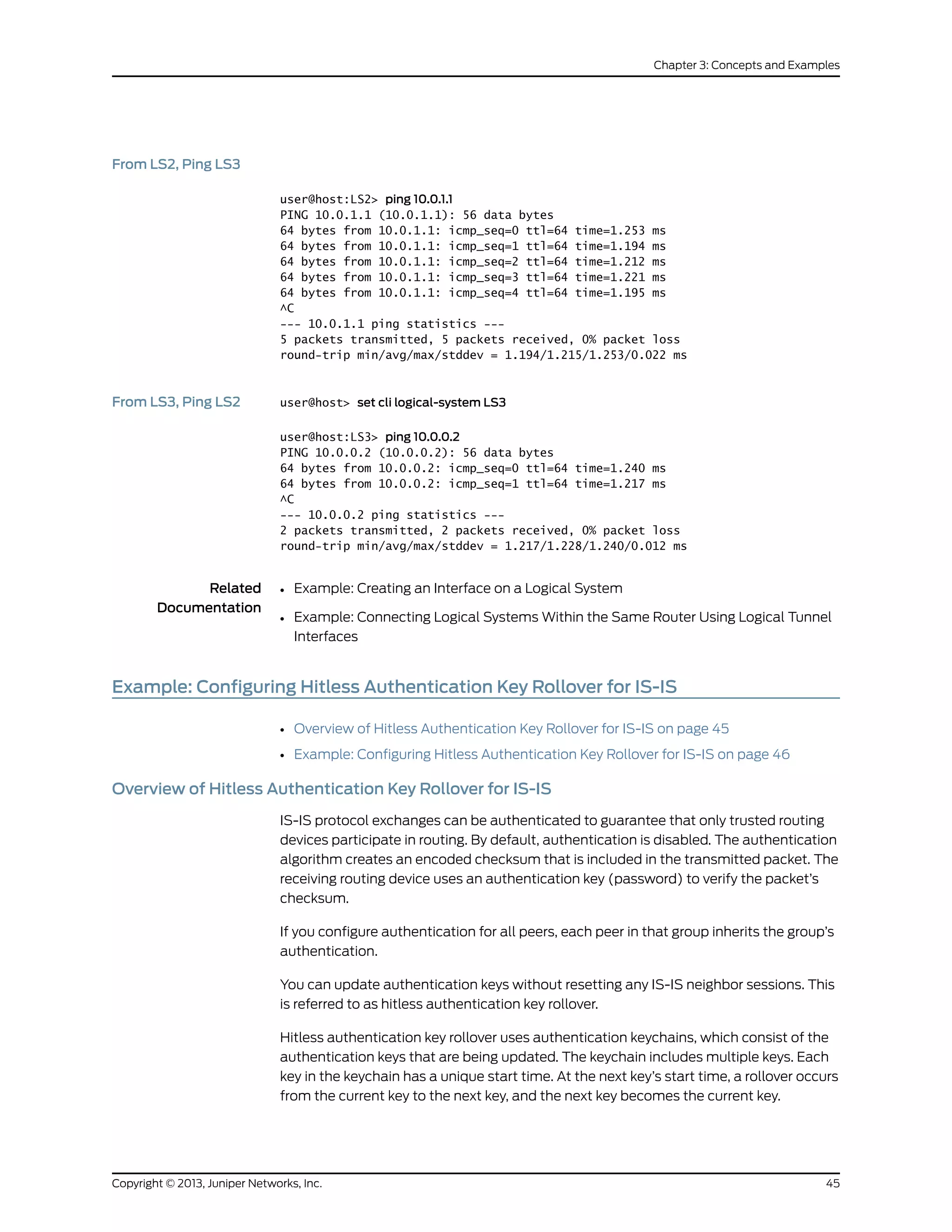
From LS1, Ping LS3 user@host> set cli logical-system LS1
user@host:LS1> ping 10.0.2.1
PING 10.0.2.1 (10.0.2.1): 56 data bytes
64 bytes from 10.0.2.1: icmp_seq=0 ttl=63 time=1.264 ms
64 bytes from 10.0.2.1: icmp_seq=1 ttl=63 time=1.189 ms
64 bytes from 10.0.2.1: icmp_seq=2 ttl=63 time=1.165 ms
^C
--- 10.0.2.1 ping statistics ---
3 packets transmitted, 3 packets received, 0% packet loss
round-trip min/avg/max/stddev = 1.165/1.206/1.264/0.042 ms
From LS3, Ping LS1 user@host> set cli logical-system LS3
user@host:LS3> ping 10.0.0.1
PING 10.0.0.1 (10.0.0.1): 56 data bytes
64 bytes from 10.0.0.1: icmp_seq=0 ttl=63 time=1.254 ms
64 bytes from 10.0.0.1: icmp_seq=1 ttl=63 time=1.210 ms
^C
--- 10.0.0.1 ping statistics ---
2 packets transmitted, 2 packets received, 0% packet loss
round-trip min/avg/max/stddev = 1.210/1.232/1.254/0.022 ms
From LS1, Ping LS2 user@host> set cli logical-system LS1
user@host:LS1> ping 10.0.2.2
PING 10.0.2.2 (10.0.2.2): 56 data bytes
64 bytes from 10.0.2.2: icmp_seq=0 ttl=64 time=1.240 ms
64 bytes from 10.0.2.2: icmp_seq=1 ttl=64 time=1.204 ms
64 bytes from 10.0.2.2: icmp_seq=2 ttl=64 time=1.217 ms
^C
--- 10.0.2.2 ping statistics ---
3 packets transmitted, 3 packets received, 0% packet loss
round-trip min/avg/max/stddev = 1.204/1.220/1.240/0.015 ms
From LS2, Ping LS1 user@host> set cli logical-system LS2
user@host:LS2> ping 10.0.1.2
PING 10.0.1.2 (10.0.1.2): 56 data bytes
64 bytes from 10.0.1.2: icmp_seq=0 ttl=64 time=1.308 ms
64 bytes from 10.0.1.2: icmp_seq=1 ttl=64 time=1.235 ms
^C
--- 10.0.1.2 ping statistics ---
2 packets transmitted, 2 packets received, 0% packet loss
round-trip min/avg/max/stddev = 1.235/1.272/1.308/0.037 ms
user@host> set cli logical-system LS2
Copyright © 2013, Juniper Networks, Inc.44
IS-IS Configuration Guide](https://image.slidesharecdn.com/config-guide-routing-is-is-151104131021-lva1-app6891/75/Juniper-MX-Config-guide-routing-is-is-64-2048.jpg)
![When you configure basic (or do not include the options statement in the key
configuration) Junos OS sends and receives RFC 5304-encoded routing protocols
packets, and drops 5310-encoded routing protocol packets that are received from
other devices.
Because this setting is for IS-IS only, the TCP and the BFD protocols ignore the encoding
option configured in the key.
• secret—For each key in the keychain, you must set a secret password. This password
can be entered in either encrypted or plain text format in the secret statement. It is
always displayed in encrypted format.
• start-time—Each key must specify a start time in UTC format. Control gets passed
from one key to the next. When a configured start time arrives (based on the routing
device’s clock), the key with that start time becomes active. Start times are specified
in the local time zone for a routing device and must be unique within the key chain.
You can apply a keychain globally to all interfaces or more granularly to specific interfaces.
This example includes the following statements for applying the keychain to all interfaces
or to particular interfaces:
• authentication-key-chain—Enables you to apply a keychain at the global IS-IS level for
all Level 1 or all Level 2 interfaces.
• hello-authentication-key-chain—Enables you to apply a keychain at the individual IS-IS
interface level. The interface configuration overrides the global configuration.
Figure 6 on page 47 shows the topology used in the example.
Figure 6: Hitless Authentication Key Rollover for IS-IS
A
A
R1 R2FE/GE/XE FE/GE/XE
FE/GE/XE
SONET
R3
ISIS Level 1{ } ISIS Level 2{ }
R0
A A
B
B
B
C
g040568
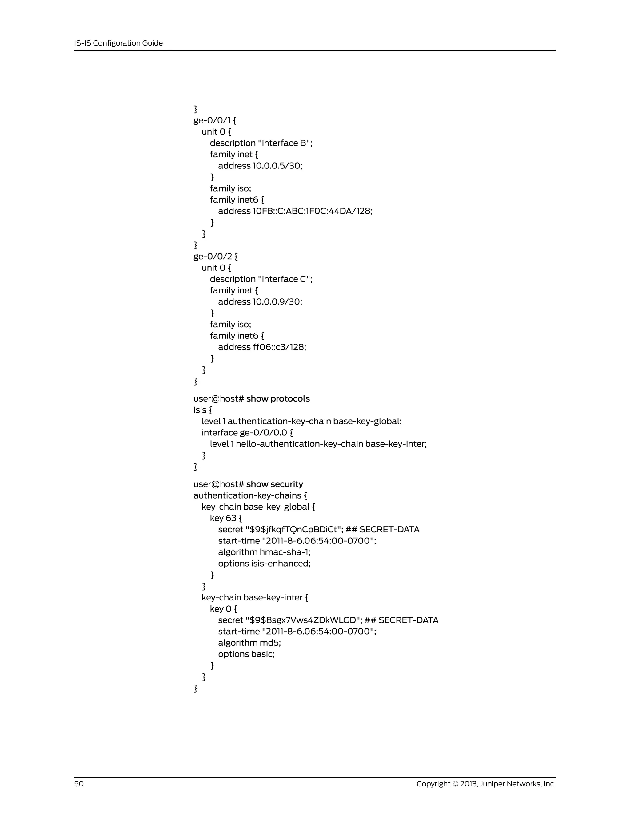
This example shows the configuration for Router R0.
Configuration
CLI Quick
Configuration
To quickly configure the hitless authentication key rollover for IS-IS, copy the following
commands and paste the commands into the CLI.
[edit]
set interfaces ge-0/0/0 unit 0 description "interface A"
set interfaces ge-0/0/0 unit 0 family inet address 10.0.0.1/30
set interfaces ge-0/0/0 unit 0 family iso
set interfaces ge-0/0/0 unit 0 family inet6 address fe80::200:f8ff:fe21:67cf/128
47Copyright © 2013, Juniper Networks, Inc.
Chapter 3: Concepts and Examples](https://image.slidesharecdn.com/config-guide-routing-is-is-151104131021-lva1-app6891/75/Juniper-MX-Config-guide-routing-is-is-67-2048.jpg)
![set interfaces ge-0/0/1 unit 0 description "interface B"
set interfaces ge-0/0/1 unit 0 family inet address 10.0.0.5/30
set interfaces ge-0/0/1 unit 0 family iso
set interfaces ge-0/0/1 unit 0 family inet6 address 10FB::C:ABC:1F0C:44DA/128
set interfaces ge-0/0/2 unit 0 description "interface C"
set interfaces ge-0/0/2 unit 0 family inet address 10.0.0.9/30
set interfaces ge-0/0/2 unit 0 family iso
set interfaces ge-0/0/2 unit 0 family inet6 address ff06::c3/128
set security authentication-key-chains key-chain base-key-global key 63 secret
"$9$jfkqfTQnCpBDiCt"
set security authentication-key-chains key-chain base-key-global key 63 start-time
"2011-8-6.06:54:00-0700"
set security authentication-key-chains key-chain base-key-global key 63 algorithm
hmac-sha-1
set security authentication-key-chains key-chain base-key-global key 63 options
isis-enhanced
set security authentication-key-chains key-chain base-key-inter key 0 secret
"$9$8sgx7Vws4ZDkWLGD"
set security authentication-key-chains key-chain base-key-inter key 0 start-time
"2011-8-6.06:54:00-0700"
set security authentication-key-chains key-chain base-key-inter key 0 algorithm md5
set security authentication-key-chains key-chain base-key-inter key 0 options basic
set protocols isis level 1 authentication-key-chain base-key-global
set protocols isis interface ge-0/0/0.0 level 1 hello-authentication-key-chain
base-key-inter
Step-by-Step
Procedure
To configure hitless authentication key rollover for IS-IS:
Configure the Router R0 interfaces.
[edit]
1.
user@host# edit interfaces ge-0/0/0 unit 0
[edit interfaces ge-0/0/0 unit 0]
user@host# set description "interface A"
user@host# set family inet address 10.0.0.1/30
user@host# set family iso
user@host# set family inet6 address fe80::200:f8ff:fe21:67cf/128
user@host# exit
[edit]
user@host# edit interfaces ge-0/0/1 unit 0
[edit interfaces ge-0/0/1 unit 0]
user@host# set interfaces ge-0/0/1 unit 0 description "interface B"
user@host# set interfaces ge-0/0/1 unit 0 family inet address 10.0.0.5/30
user@host# set interfaces ge-0/0/1 unit 0 family iso
user@host# set interfaces ge-0/0/1 unit 0 family inet6 address
10FB::C:ABC:1F0C:44DA/128
user@host# exit
[edit]
user@host# edit interfaces ge-0/0/2 unit 0
[edit interfaces ge-0/0/2 unit 0]
user@host# set description "interface C"
user@host# set family inet address 10.0.0.9/30
user@host# set interfaces ge-0/0/2 unit 0 family iso
user@host# set interfaces ge-0/0/2 unit 0 family inet6 address ff06::c3/128
user@host# exit
Copyright © 2013, Juniper Networks, Inc.48
IS-IS Configuration Guide](https://image.slidesharecdn.com/config-guide-routing-is-is-151104131021-lva1-app6891/75/Juniper-MX-Config-guide-routing-is-is-68-2048.jpg)
![2. Configure one or more authentication keys.
[edit]
user@host# edit security authentication-key-chains key-chain base-key-global
[edit security authentication-key-chains key-chain base-key-global]
user@host# set key 63 secret "$9$jfkqfTQnCpBDiCt"
user@host# set key 63 start-time "2011-8-6.06:54:00-0700"
user@host# set key 63 algorithm hmac-sha-1
user@host# set key 63 options isis-enhanced
user@host# exit
[edit]
user@host# edit security authentication-key-chains key-chain base-key-inter
[edit security authentication-key-chains key-chain base-key-inter]
user@host# set key 0 secret "$9$8sgx7Vws4ZDkWLGD"
user@host# set key 0 start-time "2011-8-6.06:54:00-0700"
user@host# set key 0 algorithm md5
user@host# set key 0 options basic
user@host# exit
3. Apply the base-key-global keychain to all Level 1 IS-IS interfaces on Router R0.
[edit]
user@host# edit protocols isis level 1
[edit protocols isis level 1]
set authentication-key-chain base-key-global
user@host# exit
4. Apply the base-key-inter keychain to the ge-0/0/0.0 interface on Router R0.
[edit]
user@host# edit protocols isis interface ge-0/0/0.0 level 1
[edit protocols isis interface ge-0/0/0.0 level 1]
set hello-authentication-key-chain base-key-inter
user@host# exit
5. If you are done configuring the device, commit the configuration.
[edit]
user@host# commit
Results
Confirm your configuration by entering the show interfaces, show protocols, and show
security commands.
user@host# show interfaces
ge-0/0/0 {
unit 0 {
description "interface A";
family inet {
address 10.0.0.1/30;
}
family iso;
family inet6 {
address fe80::200:f8ff:fe21:67cf/128;
}
}
49Copyright © 2013, Juniper Networks, Inc.
Chapter 3: Concepts and Examples](https://image.slidesharecdn.com/config-guide-routing-is-is-151104131021-lva1-app6891/75/Juniper-MX-Config-guide-routing-is-is-69-2048.jpg)
![Figure 7: IS-IS Route Redistribution Topology
lo0:172.16.3.5
fe-1/2/0
.38 10.0.0.36/30
IS-IS
49.0002
fe-1/2/1
.37
.45 fe-1/2/0
lo0:172.16.9.7
fe-1/2/0
R3
R1 R2
10.0.0.44/30
.46
OSPF
(192.168.0-3/24)
g041258
“CLI Quick Configuration” on page 52 shows the configuration for all of the devices in
Figure 7 on page 52. The section“Step-by-Step Procedure” on page 53 describes the
steps on Device R2. “Step-by-Step Procedure” on page 54 describes the steps on Device
R3.
Configuration
CLI Quick
Configuration
To quickly configure this example, copy the following commands, paste them into a text
file, remove any line breaks, change any details necessary to match your network
configuration, and then copy and paste the commands into the CLI at the [edit] hierarchy
level.
Device R1 set interfaces fe-1/2/0 unit 0 description to-R7
set interfaces fe-1/2/0 unit 0 family inet address 10.0.0.38/30
set interfaces fe-1/2/0 unit 0 family iso
set interfaces lo0 unit 0 family inet address 172.16.3.5/32
set interfaces lo0 unit 0 family iso address 49.0002.0172.0016.0305.00
set protocols isis interface fe-1/2/0.38
set protocols isis interface lo0.0
Device R2 set interfaces fe-1/2/1 unit 0 description to-R5
set interfaces fe-1/2/1 unit 0 family inet address 10.0.0.37/30
set interfaces fe-1/2/1 unit 0 family iso
set interfaces fe-1/2/0 unit 0 description to-OSPF-network
set interfaces fe-1/2/0 unit 0 family inet address 10.0.0.45/30
set interfaces lo0 unit 0 family inet address 172.16.9.7/32
set interfaces lo0 unit 0 family iso address 49.0002.0172.0016.0907.00
set protocols isis export ospf-isis
set protocols isis export send-direct-to-isis-neighbors
set protocols isis interface fe-1/2/1.0
set protocols isis interface lo0.0
Copyright © 2013, Juniper Networks, Inc.52
IS-IS Configuration Guide](https://image.slidesharecdn.com/config-guide-routing-is-is-151104131021-lva1-app6891/75/Juniper-MX-Config-guide-routing-is-is-72-2048.jpg)
![set protocols ospf export send-direct-to-ospf-neighbors
set protocols ospf area 0.0.0.1 interface fe-1/2/0.0
set protocols ospf area 0.0.0.1 interface lo0.0 passive
set policy-options policy-statement ospf-isis term 1 from protocol ospf
set policy-options policy-statement ospf-isis term 1 from route-filter 192.168.0.0/22
longer
set policy-options policy-statement ospf-isis term 1 then accept
set policy-options policy-statement send-direct-to-isis-neighbors from protocol direct
set policy-options policy-statement send-direct-to-isis-neighbors from route-filter
10.0.0.44/30 exact
set policy-options policy-statement send-direct-to-isis-neighbors then accept
set policy-options policy-statement send-direct-to-ospf-neighbors from protocol direct
set policy-options policy-statement send-direct-to-ospf-neighbors from route-filter
10.0.0.36/30 exact
set policy-options policy-statement send-direct-to-ospf-neighbors then accept
Device R3 set interfaces fe-1/2/0 unit 0 family inet address 10.0.0.46/30
set interfaces lo0 unit 0 family inet address 192.168.1.1/32
set interfaces lo0 unit 0 family inet address 192.168.2.1/32
set interfaces lo0 unit 0 family inet address 192.168.3.1/32
set interfaces lo0 unit 0 family inet address 192.168.0.1/32
set protocols ospf export ospf
set protocols ospf area 0.0.0.1 interface fe-1/2/0.0
set protocols ospf area 0.0.0.1 interface lo0.0 passive
set policy-options policy-statement ospf term 1 from protocol static
set policy-options policy-statement ospf term 1 then accept
set routing-options static route 192.168.0.0/24 discard
set routing-options static route 192.168.1.0/24 discard
set routing-options static route 192.168.3.0/24 discard
set routing-options static route 192.168.2.0/24 discard
Step-by-Step
Procedure
To configure Device R2:
Configure the network interfaces.1.
[edit interfaces]
user@R2# set fe-1/2/1 unit 0 description to-R5
user@R2# set fe-1/2/1 unit 0 family inet address 10.0.0.37/30
user@R2# set fe-1/2/1 unit 0 family iso
user@R2# set fe-1/2/0 unit 0 description to-OSPF-network
user@R2# set fe-1/2/0 unit 0 family inet address 10.0.0.45/30
user@R2# set lo0 unit 0 family inet address 172.16.9.7/32
user@R2# set lo0 unit 0 family iso address 49.0002.0172.0016.0907.00
2. Configure IS-IS on the interface facing Device R1 and the loopback interface.
[edit protocols isis]
user@R2# set interface fe-1/2/1.0
user@R2# set interface lo0.0
3. Configure the policy that enables Device R1 to reach the 10.0.0.44/30 network.
[edit policy-options policy-statement send-direct-to-isis-neighbors]
user@R2# set from protocol direct
user@R2# set from route-filter 10.0.0.44/30 exact
53Copyright © 2013, Juniper Networks, Inc.
Chapter 3: Concepts and Examples](https://image.slidesharecdn.com/config-guide-routing-is-is-151104131021-lva1-app6891/75/Juniper-MX-Config-guide-routing-is-is-73-2048.jpg)
![user@R2# set then accept
4. Apply the policy that enables Device R1 to reach the 10.0.0.44/30 network.
[edit protocols isis]
user@R2# set export send-direct-to-isis-neighbors
5. Configure OSPF on the interfaces.
[edit protocols ospf]
user@R2# set area 0.0.0.1 interface fe-1/2/0.0
user@R2# set area 0.0.0.1 interface lo0.0 passive
6. Configure the OSPF route redistribution policy.
[edit policy-options policy-statement ospf-isis term 1]
user@R2# set from protocol ospf
user@R2# set from route-filter 192.168.0.0/22 longer
user@R2# set then accept
7. Apply the OSPF route redistribution policy to the IS-IS instance.
[edit protocols isis]
user@R2# set export ospf-isis
8. Configure the policy that enables Device R3 to reach the 10.0.0.36/30 network.
[edit policy-options policy-statement send-direct-to-ospf-neighbors]
user@R2# set from protocol direct
user@R2# set from route-filter 10.0.0.36/30 exact
user@R2# set then accept
9. Apply the policy that enables Device R3 to reach the 10.0.0.36/30 network.
[edit protocols ospf]
user@R2# set export send-direct-to-ospf-neighbors
Step-by-Step
Procedure
The following example requires you to navigate various levels in the configuration
hierarchy. For information about navigating the CLI, see Using the CLI Editor in
Configuration Mode in the CLI User Guide.
To configure multi-level IS-IS:
1. Configure the network interfaces.
Multiple addresses are configured on the loopback interface to simulate multiple
route destinations.
[edit interfaces]
user@R3# set fe-1/2/0 unit 0 family inet address 10.0.0.46/30
user@R3# set lo0 unit 0 family inet address 192.168.1.1/32
user@R3# set lo0 unit 0 family inet address 192.168.2.1/32
user@R3# set lo0 unit 0 family inet address 192.168.3.1/32
user@R3# set lo0 unit 0 family inet address 192.168.0.1/32
2. Configure static routes to the loopback interface addresses.
These are the routes that are redistributed into IS-IS.
[edit routing-options static]
Copyright © 2013, Juniper Networks, Inc.54
IS-IS Configuration Guide](https://image.slidesharecdn.com/config-guide-routing-is-is-151104131021-lva1-app6891/75/Juniper-MX-Config-guide-routing-is-is-74-2048.jpg)
![user@R3# set route 192.168.0.0/24 discard
user@R3# set route 192.168.1.0/24 discard
user@R3# set route 192.168.3.0/24 discard
user@R3# set route 192.168.2.0/24 discard
3. Configure OSPF on the interfaces.
[edit protocols ospf area 0.0.0.1]
user@R3# set interface fe-1/2/0.0
user@R3# set interface lo0.0 passive
4. Configure the OSPF policy to export the static routes.
[edit policy-options policy-statement ospf term 1]
user@R3# set from protocol static
user@R3# set then accept
5. Apply the OSPF export policy.
[edit protocols ospf]
user@R3# set export ospf
Results From configuration mode, confirm your configuration by entering the show interfaces and
show protocols commands. If the output does not display the intended configuration,
repeat the configuration instructions in this example to correct it.
Device R2 user@R2# show interfaces
fe-1/2/1 {
unit 37 {
description to-R5;
family inet {
address 10.0.0.37/30;
}
family iso;
}
}
fe-1/2/0 {
unit 45 {
description to-OSPF-network;
family inet {
address 10.0.0.45/30;
}
}
}
lo0 {
unit 0 {
family inet {
address 172.16.9.7/32;
}
family iso {
address 49.0002.0172.0016.0907.00;
}
}
}
user@R2# show protocols
isis {
55Copyright © 2013, Juniper Networks, Inc.
Chapter 3: Concepts and Examples](https://image.slidesharecdn.com/config-guide-routing-is-is-151104131021-lva1-app6891/75/Juniper-MX-Config-guide-routing-is-is-75-2048.jpg)
![export [ ospf-isis send-direct-to-isis-neighbors ];
interface fe-1/2/1.0;
interface lo0.0;
}
ospf {
export send-direct-to-ospf-neighbors;
area 0.0.0.1 {
interface fe-1/2/0.0;
interface lo0.0 {
passive;
}
}
}
user@R2# show policy-options
policy-statement ospf-isis {
term 1 {
from {
protocol ospf;
route-filter 192.168.0.0/22 longer;
}
then accept;
}
}
policy-statement send-direct-to-isis-neighbors {
from {
protocol direct;
route-filter 10.0.0.44/30 exact;
}
then accept;
}
policy-statement send-direct-to-ospf-neighbors {
from {
protocol direct;
route-filter 10.0.0.36/30 exact;
}
then accept;
}
Device R3 user@R3# show interfaces
fe-1/2/0 {
unit 46 {
family inet {
address 10.0.0.46/30;
}
}
}
lo0 {
unit 0 {
family inet {
address 192.168.1.1/32;
address 192.168.2.1/32;
address 192.168.3.1/32;
address 192.168.0.1/32;
}
}
}
Copyright © 2013, Juniper Networks, Inc.56
IS-IS Configuration Guide](https://image.slidesharecdn.com/config-guide-routing-is-is-151104131021-lva1-app6891/75/Juniper-MX-Config-guide-routing-is-is-76-2048.jpg)
![user@R3# show protocols
ospf {
export ospf;
area 0.0.0.1 {
interface fe-1/2/0.0;
interface lo0.0 {
passive;
}
}
}
user@R3# show policy-options
policy-statement ospf {
term 1 {
from protocol static;
then accept;
}
}
user@R3# show routing-options
static {
route 192.168.0.0/24 discard;
route 192.168.1.0/24 discard;
route 192.168.3.0/24 discard;
route 192.168.2.0/24 discard;
}
If you are done configuring the device, enter commit from configuration mode.
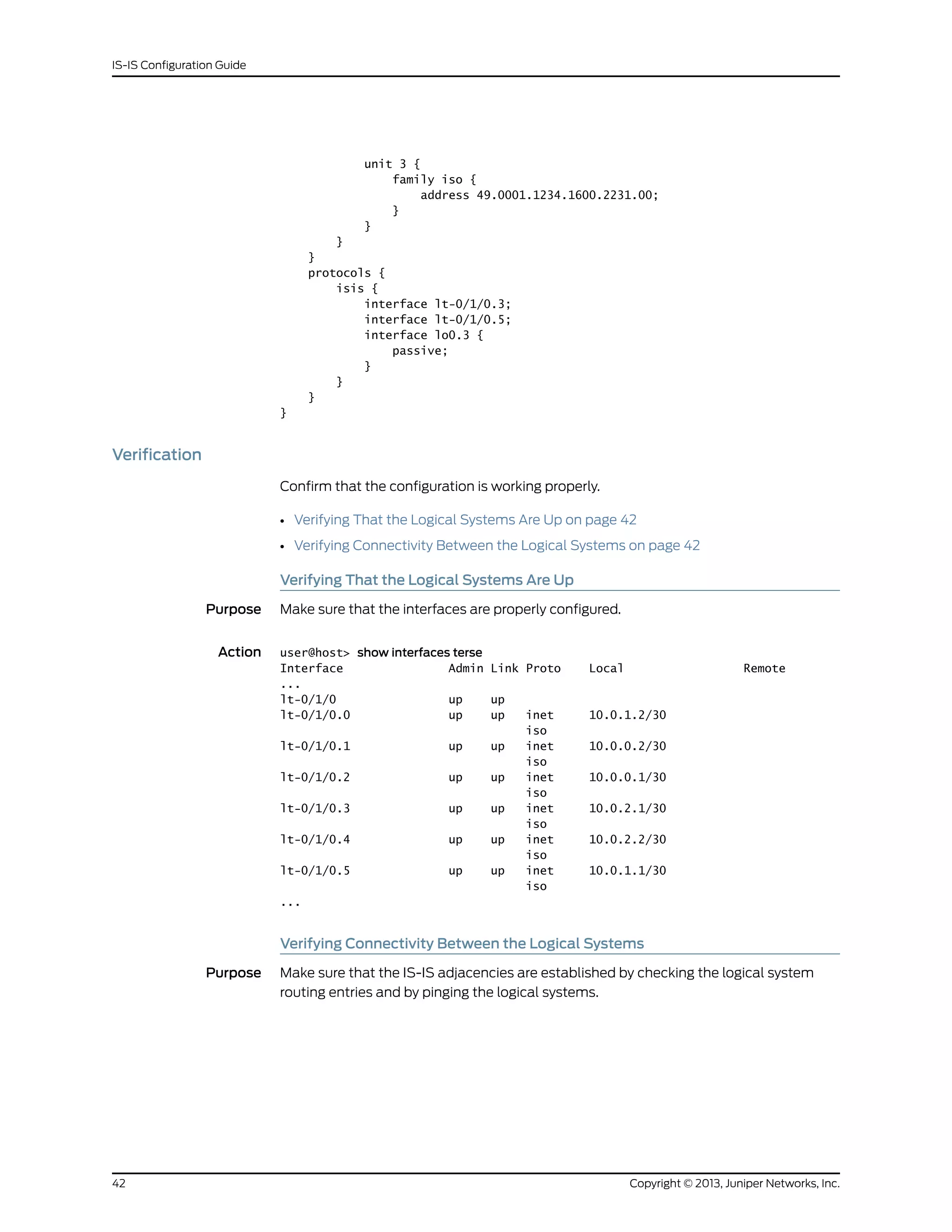
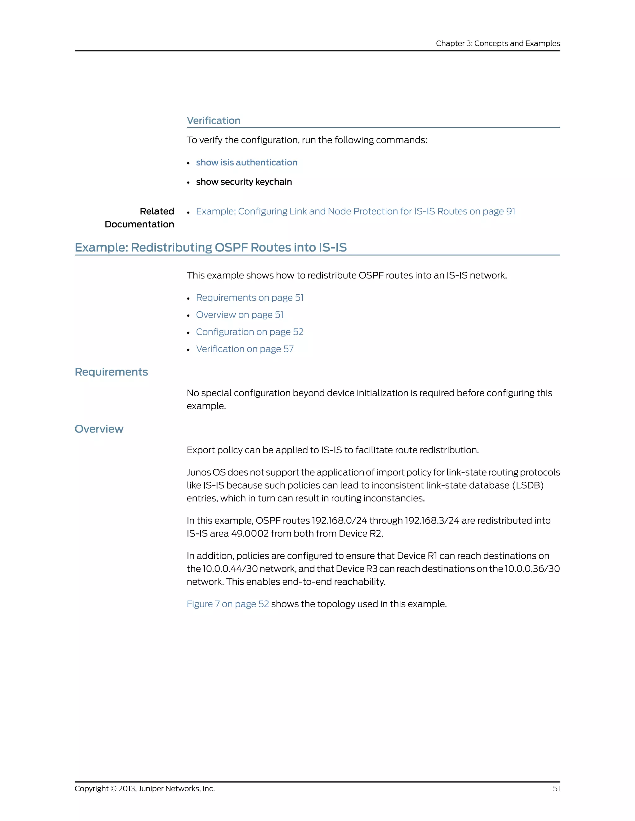
Verification
Confirm that the configuration is working properly.
• Verifying OSPF Route Advertisement on page 57
• Verifying Route Redistribution on page 58
• Verifying Connectivity on page 58
Verifying OSPF Route Advertisement
Purpose Make sure that the expected routes are advertised by OSPF.
Action From operational mode on Device R2, enter the show route protocol ospf command.
user@R2> show route protocol ospf
inet.0: 15 destinations, 15 routes (15 active, 0 holddown, 0 hidden)
+ = Active Route, - = Last Active, * = Both
192.168.0.0/24 *[OSPF/150] 03:54:21, metric 0, tag 0
> to 10.0.0.46 via fe-1/2/0.0
192.168.0.1/32 *[OSPF/10] 03:54:21, metric 1
> to 10.0.0.46 via fe-1/2/0.0
192.168.1.0/24 *[OSPF/150] 03:54:21, metric 0, tag 0
> to 10.0.0.46 via fe-1/2/0.0
192.168.1.1/32 *[OSPF/10] 03:54:21, metric 1
> to 10.0.0.46 via fe-1/2/0.0
57Copyright © 2013, Juniper Networks, Inc.
Chapter 3: Concepts and Examples](https://image.slidesharecdn.com/config-guide-routing-is-is-151104131021-lva1-app6891/75/Juniper-MX-Config-guide-routing-is-is-77-2048.jpg)
![192.168.2.0/24 *[OSPF/150] 03:54:21, metric 0, tag 0
> to 10.0.0.46 via fe-1/2/0.0
192.168.2.1/32 *[OSPF/10] 03:54:21, metric 1
> to 10.0.0.46 via fe-1/2/0.0
192.168.3.0/24 *[OSPF/150] 03:54:21, metric 0, tag 0
> to 10.0.0.46 via fe-1/2/0.0
192.168.3.1/32 *[OSPF/10] 03:54:21, metric 1
> to 10.0.0.46 via fe-1/2/0.0
224.0.0.5/32 *[OSPF/10] 03:56:03, metric 1
MultiRecv
iso.0: 1 destinations, 1 routes (1 active, 0 holddown, 0 hidden)
Meaning The 192.168/16 routes are advertised by OSPF.
Verifying Route Redistribution
Purpose Make sure that the expected routes are redistributed from OSPF into IS-IS.
Action From operational mode on Device R1, enter the show route protocol isis command.
user@R1> show route protocol isis
inet.0: 13 destinations, 13 routes (13 active, 0 holddown, 0 hidden)
+ = Active Route, - = Last Active, * = Both
10.0.0.44/30 *[IS-IS/160] 03:45:24, metric 20
> to 10.0.0.37 via fe-1/2/0.0
172.16.9.7/32 *[IS-IS/15] 03:49:46, metric 10
> to 10.0.0.37 via fe-1/2/0.0
192.168.0.0/24 *[IS-IS/160] 03:49:46, metric 10
> to 10.0.0.37 via fe-1/2/0.0
192.168.0.1/32 *[IS-IS/160] 03:49:46, metric 11, tag2 1
> to 10.0.0.37 via fe-1/2/0.0
192.168.1.0/24 *[IS-IS/160] 03:49:46, metric 10
> to 10.0.0.37 via fe-1/2/0.0
192.168.1.1/32 *[IS-IS/160] 03:49:46, metric 11, tag2 1
> to 10.0.0.37 via fe-1/2/0.0
192.168.2.0/24 *[IS-IS/160] 03:49:46, metric 10
> to 10.0.0.37 via fe-1/2/0.0
192.168.2.1/32 *[IS-IS/160] 03:49:46, metric 11, tag2 1
> to 10.0.0.37 via fe-1/2/0.0
192.168.3.0/24 *[IS-IS/160] 03:49:46, metric 10
> to 10.0.0.37 via fe-1/2/0.0
192.168.3.1/32 *[IS-IS/160] 03:49:46, metric 11, tag2 1
> to 10.0.0.37 via fe-1/2/0.0
iso.0: 1 destinations, 1 routes (1 active, 0 holddown, 0 hidden)
Meaning The 192.168/16 routes are redistributed into IS-IS.
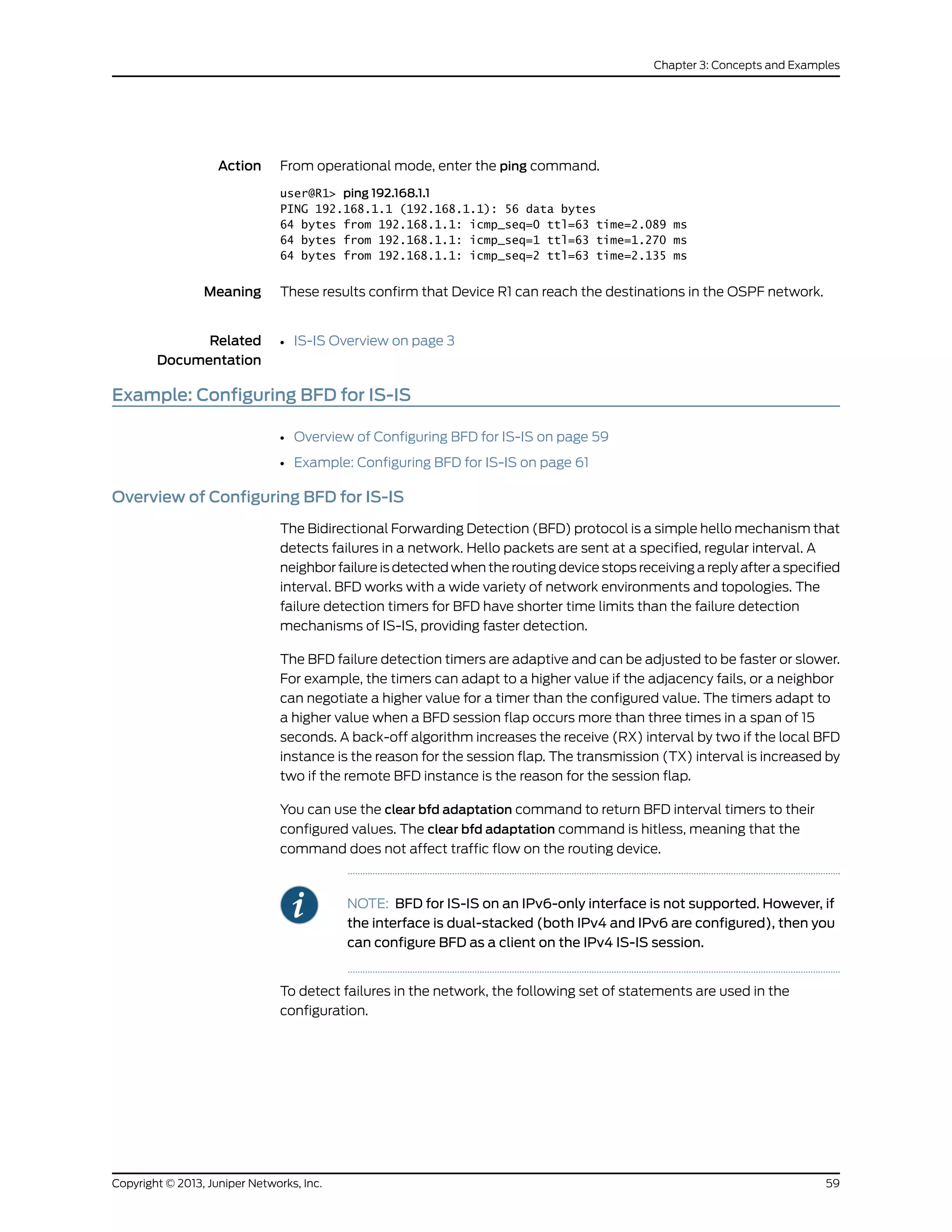
Verifying Connectivity
Purpose Check that Device R1 can reach the destinations on Device R3.
Copyright © 2013, Juniper Networks, Inc.58
IS-IS Configuration Guide](https://image.slidesharecdn.com/config-guide-routing-is-is-151104131021-lva1-app6891/75/Juniper-MX-Config-guide-routing-is-is-78-2048.jpg)
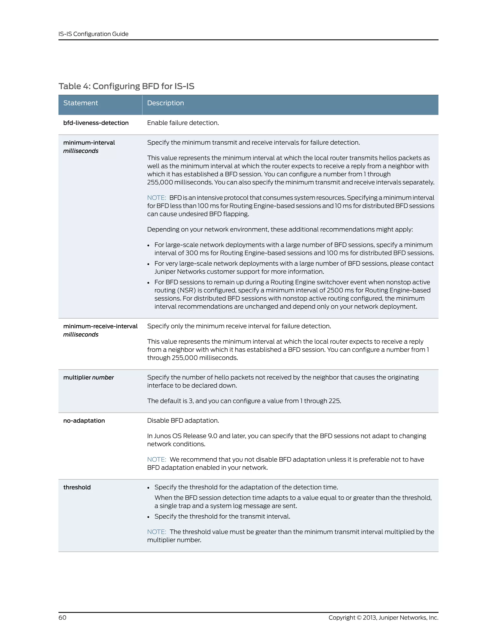
![Table 4: Configuring BFD for IS-IS (continued)
DescriptionStatement
Specify the minimum transmit interval for failure detection.
This value represents the minimum interval at which the local routing device transmits hello packets
to the neighbor with which it has established a BFD session. You can configure a value from 1
through 255,000 milliseconds.
transmit-interval
minimum-interval
Specify the BFD version used for detection.
The default is to have the version detected automatically.
version
NOTE: You can trace BFD operations by including the traceoptions statement
at the [edit protocols bfd] hierarchy level.
For a list of hierarchy levels at which you can include these statements, see the statement
summary sections for these statements.
Example: Configuring BFD for IS-IS
This example describes how to configure the Bidirectional Forwarding Detection (BFD)
protocol to detect failures in an IS-IS network.
• Requirements on page 61
• Overview on page 61
• Configuration on page 62
• Verification on page 65
Requirements
Before you begin, configure IS-IS on both routers. See “Example: Configuring IS-IS” on
page 15 for information about the required IS-IS configuration.
This example uses the following hardware and software components:
• Junos OS Release 7.3 or later
• M Series, MX Series, and T Series routers
Overview
This example shows two routers connected to each other. A loopback interface is
configured on each router. IS-IS and BFD protocols are configured on both routers.
Figure 8 on page 62 shows the sample network.
61Copyright © 2013, Juniper Networks, Inc.
Chapter 3: Concepts and Examples](https://image.slidesharecdn.com/config-guide-routing-is-is-151104131021-lva1-app6891/75/Juniper-MX-Config-guide-routing-is-is-81-2048.jpg)
![Figure 8: Configuring BFD on IS-IS
Configuration
CLI Quick
Configuration
To quickly configure this example, copy the following commands, paste them into a text
file, remove any line breaks, change any details necessary to match your network
configuration, and then copy and paste the commands into the CLI at the [edit] hierarchy
level.
Router R1
set protocols isis interface so-0/0/0 bfd-liveness-detection detection-time threshold 5
set protocols isis interface so-0/0/0 bfd-liveness-detection minimum-interval 2
set protocols isis interface so-0/0/0 bfd-liveness-detection minimum-receive-interval 1
set protocols isis interface so-0/0/0 bfd-liveness-detection no-adaptation
set protocols isis interface so-0/0/0 bfd-liveness-detection transmit-interval threshold 3
set protocols isis interface so-0/0/0 bfd-liveness-detection transmit-interval
minimum-interval 1
set protocols isis interface so-0/0/0 bfd-liveness-detection multiplier 2
set protocols isis interface so-0/0/0 bfd-liveness-detection version automatic
Router R2
set protocols isis interface so-0/0/0 bfd-liveness-detection detection-time threshold 6
set protocols isis interface so-0/0/0 bfd-liveness-detection minimum-interval 3
set protocols isis interface so-0/0/0 bfd-liveness-detection minimum-receive-interval 1
set protocols isis interface so-0/0/0 bfd-liveness-detection no-adaptation
set protocols isis interface so-0/0/0 bfd-liveness-detection transmit-interval threshold 4
set protocols isis interface so-0/0/0 bfd-liveness-detection transmit-interval
minimum-interval 1
set protocols isis interface so-0/0/0 bfd-liveness-detection multiplier 2
set protocols isis interface so-0/0/0 bfd-liveness-detection version automatic
Copyright © 2013, Juniper Networks, Inc.62
IS-IS Configuration Guide](https://image.slidesharecdn.com/config-guide-routing-is-is-151104131021-lva1-app6891/75/Juniper-MX-Config-guide-routing-is-is-82-2048.jpg)
![Step-by-Step
Procedure
The following example requires you to navigate various levels in the configuration
hierarchy. For information about navigating the CLI, see the CLI User Guide.
NOTE: TosimplyconfigureBFDforIS-IS,onlytheminimum-interval statement
is required. The BFD protocol selects default parameters for all the other
configuration statements when you use the bfd-liveness-detection statement
without specifying any parameters.
NOTE: You can change parameters at any time without stopping or restarting
the existing session. BFD automatically adjusts to the new parameter value.
However, no changes to BFD parameters take place until the values
resynchronize with each BFD peer.
To configure BFD for IS-IS on Routers R1 and R2:
1. Enable BFD failure detection for IS-IS.
[edit protocols isis]
user@R1# set interface so-0/0/0 bfd-liveness-detection
[edit protocols isis]
user@R2# set interface so-0/0/0 bfd-liveness-detection
2. Configure the threshold for the adaptation of the detection time, which must be
greater than the multiplier number multiplied by the minimum interval.
[edit protocols isis interface so-0/0/0 bfd-liveness-detection]
user@R1# set detection-time threshold 5
[edit protocols isis interface so-0/0/0 bfd-liveness-detection]
user@R2# set detection-time threshold 6
3. Configure the minimum transmit and receive intervals for failure detection.
[edit protocols isis interface so-0/0/0 bfd-liveness-detection]
user@R1# set minimum-interval 2
[edit protocols isis interface so-0/0/0 bfd-liveness-detection]
user@R2# set minimum-interval 3
4. Configure only the minimum receive interval for failure detection.
[edit protocols isis interface so-0/0/0 bfd-liveness-detection]
user@R1# set minimum-receive-interval 1
[edit protocols isis interface so-0/0/0 bfd-liveness-detection]
user@R2# set minimum-receive-interval 1
5. Disable BFD adaptation.
[edit protocols isis interface so-0/0/0 bfd-liveness-detection]
user@R1# set no-adaptation
[edit protocols isis interface so-0/0/0 bfd-liveness-detection]
63Copyright © 2013, Juniper Networks, Inc.
Chapter 3: Concepts and Examples](https://image.slidesharecdn.com/config-guide-routing-is-is-151104131021-lva1-app6891/75/Juniper-MX-Config-guide-routing-is-is-83-2048.jpg)
![user@R2# set no-adaptation
6. Configure the threshold for the transmit interval, which must be greater than the
minimum transmit interval.
[edit protocols isis interface so-0/0/0 bfd-liveness-detection]
user@R1# set transmit-interval threshold 3
[edit protocols isis interface so-0/0/0 bfd-liveness-detection]
user@R2# set transmit-interval threshold 4
7. Configure the minimum transmit interval for failure detection.
[edit protocols isis interface so-0/0/0 bfd-liveness-detection]
user@R1# set transmit-interval minimum-interval 1
[edit protocols isis interface so-0/0/0 bfd-liveness-detection]
user@R2# set transmit-interval minimum-interval 1
8. Configure the multiplier number, which is the number of hello packets not received
by the neighbor that causes the originating interface to be declared down.
[edit protocols isis interface so-0/0/0 bfd-liveness-detection]
user@R1# set multiplier 2
[edit protocols isis interface so-0/0/0 bfd-liveness-detection]
user@R2# set multiplier 2
9. Configure the BFD version used for detection.
The default is to have the version detected automatically.
[edit protocols isis interface so-0/0/0 bfd-liveness-detection]
user@R1# set version automatic
[edit protocols isis interface so-0/0/0 bfd-liveness-detection]
user@R2# set version automatic
Results
Confirm your configuration by issuing the show protocols isis interface command.
user@R1# show protocols isis interface so-0/0/0
bfd-liveness-detection {
version automatic;
minimum-interval 2;
minimum-receive-interval 1;
multiplier 2;
no-adaptation;
transmit-interval {
minimum-interval 1;
threshold 3;
}
detection-time {
threshold 5;
}
}
...
user@R2# show protocols isis interface so-0/0/0
Copyright © 2013, Juniper Networks, Inc.64
IS-IS Configuration Guide](https://image.slidesharecdn.com/config-guide-routing-is-is-151104131021-lva1-app6891/75/Juniper-MX-Config-guide-routing-is-is-84-2048.jpg)
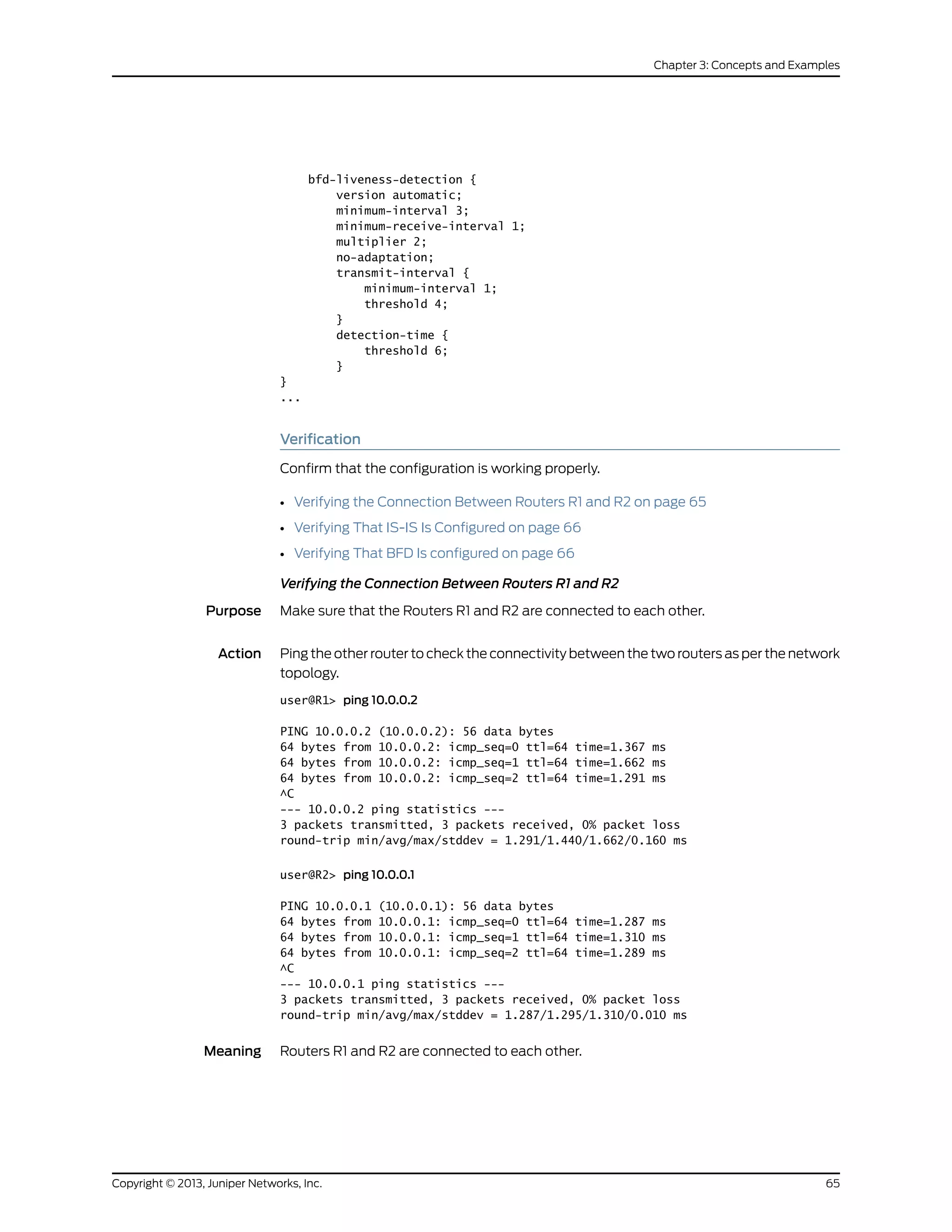
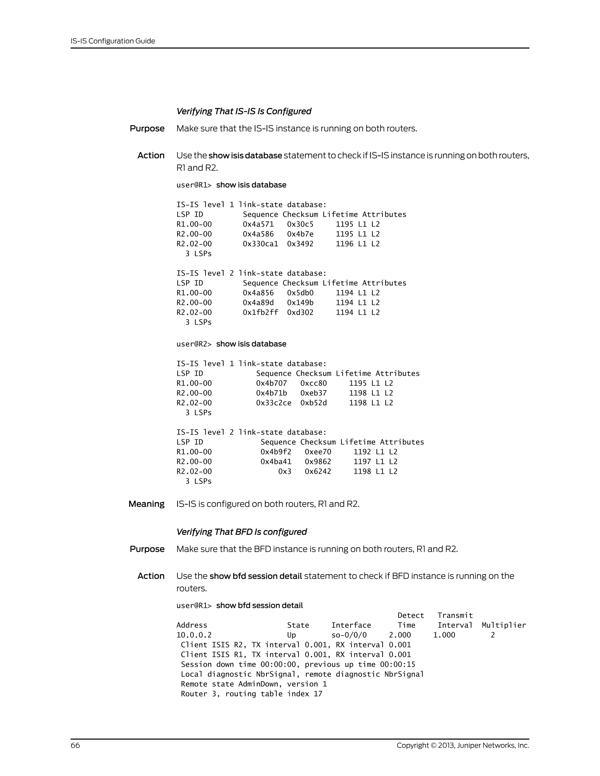
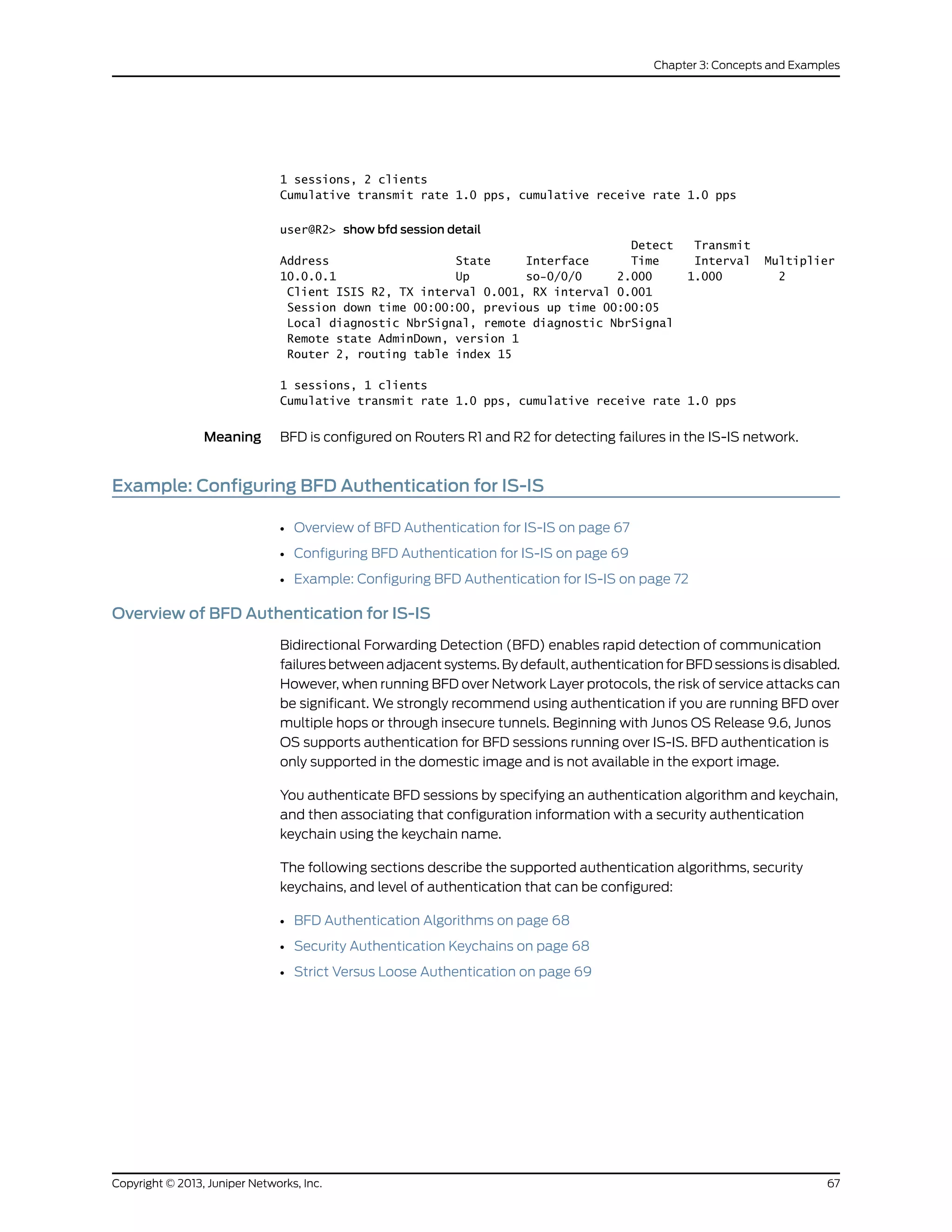
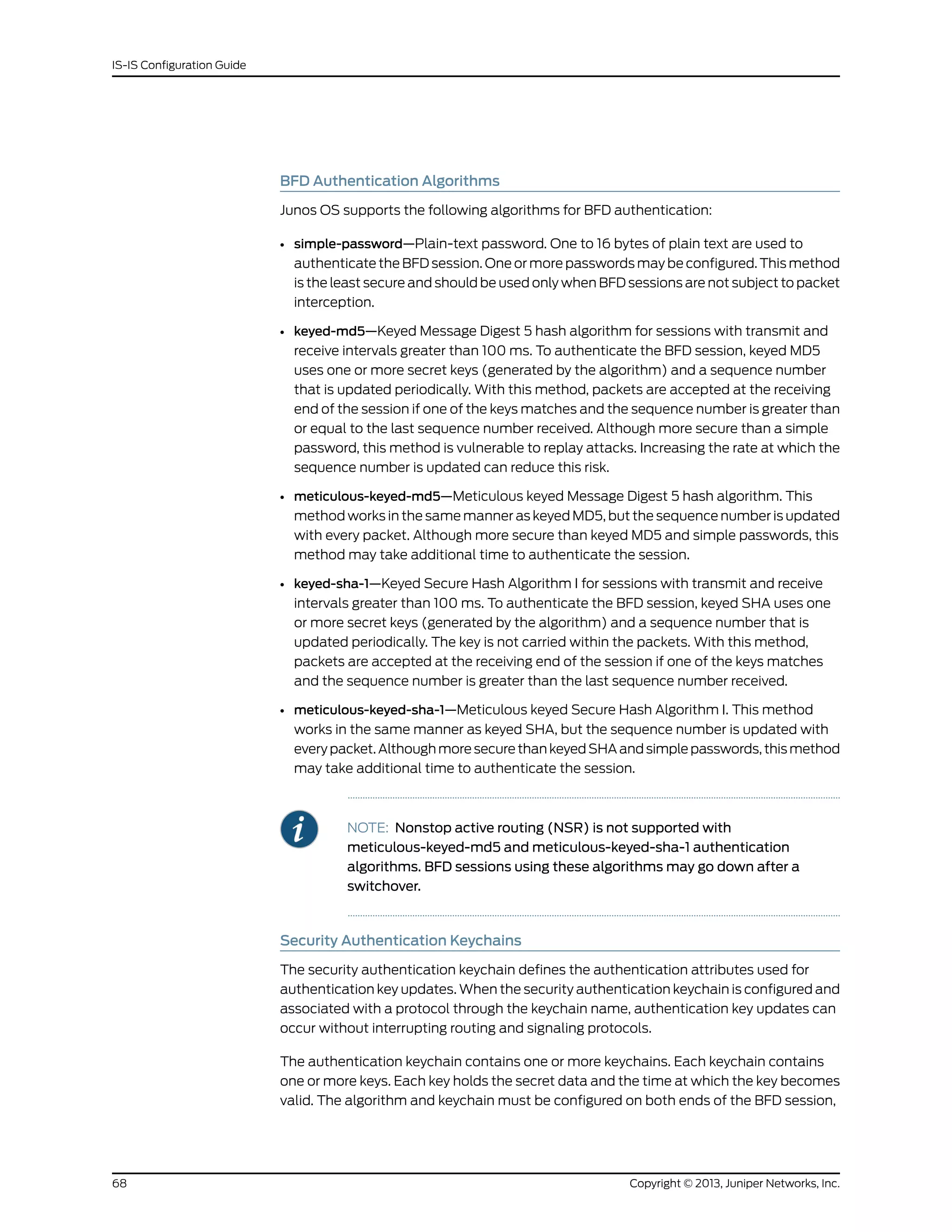
![and they must match. Any mismatch in configuration prevents the BFD session from
being created.
BFD allows multiple clients per session, and each client can have its own keychain and
algorithm defined. To avoid confusion, we recommend specifying only one security
authentication keychain.
Strict Versus Loose Authentication
By default, strict authentication is enabled and authentication is checked at both ends
of each BFD session. Optionally, to smooth migration from nonauthenticated sessions
to authenticated sessions, you can configure loose checking. When loose checking is
configured, packets are accepted without authentication being checked at each end of
the session. This feature is intended for transitional periods only.
Configuring BFD Authentication for IS-IS
Beginning with Junos OS Release 9.6, you can configure authentication for BFD sessions
running over IS-IS. Routing instances are also supported. Only three steps are needed to
configure authentication on a BFD session:
1. Specify the BFD authentication algorithm for the IS-IS protocol.
2. Associate the authentication keychain with the IS-IS protocol.
3. Configure the related security authentication keychain.
The following sections provide instructions for configuring and viewing BFD authentication
on IS-IS:
• Configuring BFD Authentication Parameters on page 69
• Viewing Authentication Information for BFD Sessions on page 70
Configuring BFD Authentication Parameters
To configure BFD authentication:
1. Specify the algorithm (keyed-md5, keyed-sha-1, meticulous-keyed-md5,
meticulous-keyed-sha-1, or simple-password) to use for BFD authentication on an
IS-IS route or routing instance.
[edit]
user@host# set protocols isis interface if1-isis bfd-liveness-detection authentication
algorithm keyed-sha-1
NOTE: Nonstop active routing (NSR) is not supported with the
meticulous-keyed-md5 and meticulous-keyed-sha-1 authentication
algorithms. BFD sessions using these algorithms may go down after a
switchover.
2. Specify the keychain to be used to associate BFD sessions on the specified IS-IS route
or routing instance with the unique security authentication keychain attributes. This
69Copyright © 2013, Juniper Networks, Inc.
Chapter 3: Concepts and Examples](https://image.slidesharecdn.com/config-guide-routing-is-is-151104131021-lva1-app6891/75/Juniper-MX-Config-guide-routing-is-is-89-2048.jpg)
![should match the keychain name configured at the [edit security authentication
key-chains] hierarchy level.
[edit]
user@host# set protocols isis interface if1-isis bfd-liveness-detection authentication
keychain bfd-isis
NOTE: The algorithm and keychain must be configured on both ends of
the BFD session, and they must match. Any mismatch in configuration
prevents the BFD session from being created.
3. Specify the unique security authentication information for BFD sessions:
• The matching keychain name as specified in Step 2.
• At least one key, a unique integer between 0 and 63. Creating multiple keys allows
multiple clients to use the BFD session.
• The secret data used to allow access to the session.
• The time at which the authentication key becomes active, yyyy-mm-dd.hh:mm:ss.
[edit security]
user@host# set authentication-key-chains key-chain bfd-sr4 key 53 secret
$9$ggaJDmPQ6/tJgF/AtREVsyPsnCtUHm start-time 2009-06-14.10:00:00
4. (Optional) Specify loose authentication checking if you are transitioning from
nonauthenticated sessions to authenticated sessions.
[edit]
user@host> set protocols isis interface if1-isis bfd-liveness-detection authentication
loose-check
5. (Optional) View your configuration using the show bfd session detail or show bfd
session extensive command.
6. Repeat these steps to configure the other end of the BFD session.
NOTE: BFD authentication is only supported in the domestic image and is
not available in the export image.
Viewing Authentication Information for BFD Sessions
You can view the existing BFD authentication configuration using the show bfd session
detail and show bfd session extensive commands.
The following example shows BFD authentication configured for the if1-isis interface. It
specifies the keyed SHA-1 authentication algorithm and a keychain name of bfd-isis. The
authentication keychain is configured with two keys. Key 1 contains the secret data
“$9$ggaJDmPQ6/tJgF/AtREVsyPsnCtUHm” and a start time of June 1, 2009, at 9:46:02
AM PST. Key 2 contains the secret data “$9$a5jiKW9l.reP38ny.TszF2/9” and a start time
of June 1, 2009, at 3:29:20 PM PST.
Copyright © 2013, Juniper Networks, Inc.70
IS-IS Configuration Guide](https://image.slidesharecdn.com/config-guide-routing-is-is-151104131021-lva1-app6891/75/Juniper-MX-Config-guide-routing-is-is-90-2048.jpg)
![[edit protocols isis]
interface if1-isis {
bfd-liveness-detection {
authentication {
algorithm keyed-sha-1;
key-chain bfd-isis;
}
}
}
[edit security]
authentication key-chains {
key-chain bfd-isis {
key 1 {
secret “$9$ggaJDmPQ6/tJgF/AtREVsyPsnCtUHm”;
start-time “2009-6-1.09:46:02 -0700”;
}
key 2 {
secret “$9$a5jiKW9l.reP38ny.TszF2/9”;
start-time “2009-6-1.15:29:20 -0700”;
}
}
}
If you commit these updates to your configuration, you see output similar to the following.
In the output for the show bfd sessions detail command, Authenticate is displayed to
indicate that BFD authentication is configured. For more information about the
configuration, use the show bfd sessions extensive command. The output for this
command provides the keychain name, the authentication algorithm and mode for each
client in the session, and the overall BFD authentication configuration status, keychain
name, and authentication algorithm and mode.
71Copyright © 2013, Juniper Networks, Inc.
Chapter 3: Concepts and Examples](https://image.slidesharecdn.com/config-guide-routing-is-is-151104131021-lva1-app6891/75/Juniper-MX-Config-guide-routing-is-is-91-2048.jpg)
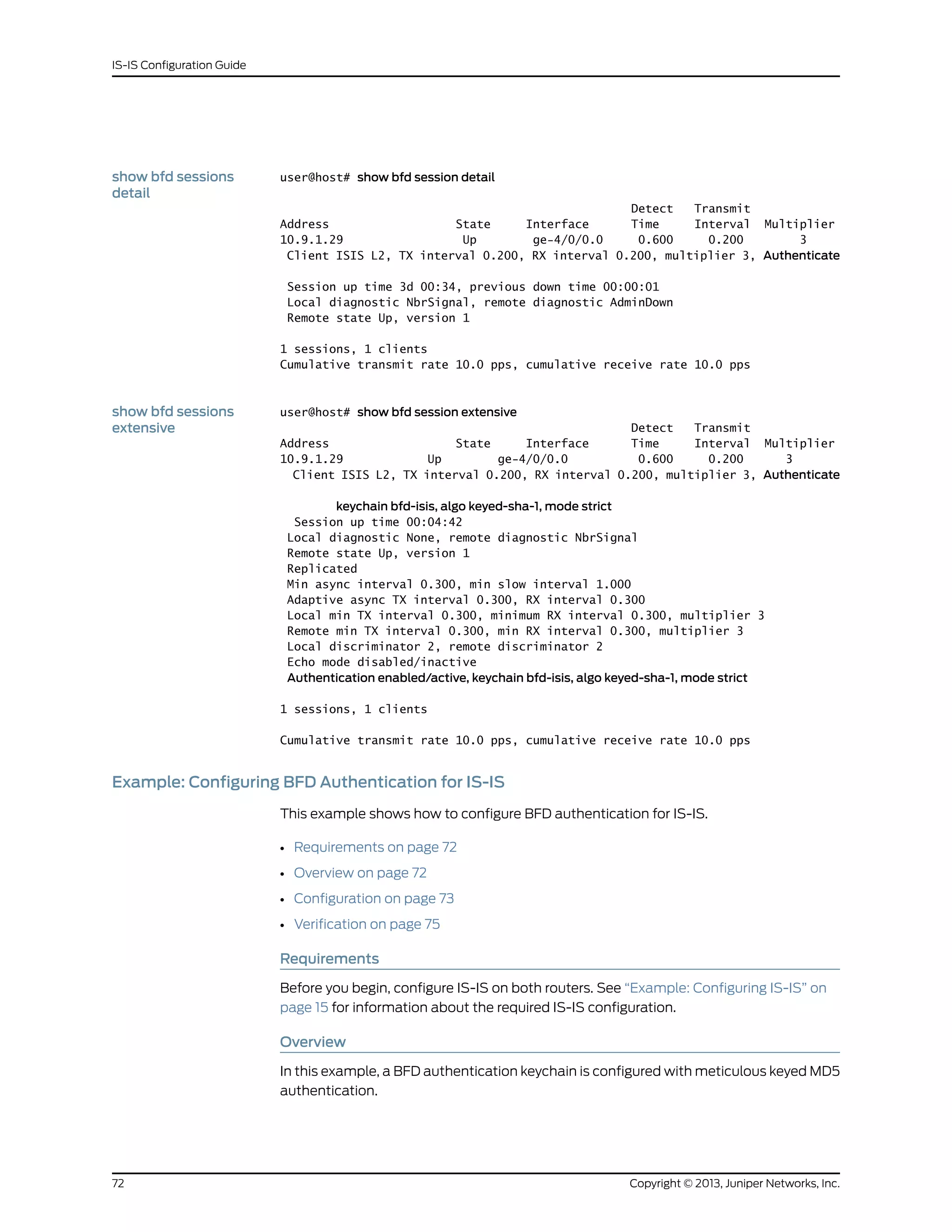
![Figure 9 on page 73 shows the topology used in this example.
Figure 9: IS-IS BFD Authentication Topology
R1
.1
10.0.0.0/30
.2
R2
lo0:192.168.0.1 lo0:192.168.0.2
g041282
“CLI Quick Configuration” on page 73 shows the configuration for both of the devices in
Figure 9 on page 73. The section “Step-by-Step Procedure” on page 74 describes the
steps on Device R1.
Configuration
CLI Quick
Configuration
To quickly configure this example, copy the following commands, paste them into a text
file, remove any line breaks, change any details necessary to match your network
configuration, and then copy and paste the commands into the CLI at the [edit] hierarchy
level.
Device R1 set security authentication-key-chains key-chain secret123 description for-isis-bfd
set security authentication-key-chains key-chain secret123 key 1 secret "$9$cW-yrv"
set security authentication-key-chains key-chain secret123 key 1 start-time
"2012-5-31.13:00:00 -0700"
set security authentication-key-chains key-chain secret123 key 2 secret "$9$m5T3"
set security authentication-key-chains key-chain secret123 key 2 start-time
"2013-5-31.13:00:00 -0700"
set security authentication-key-chains key-chain secret123 key 3 secret "$9$mTQn"
set security authentication-key-chains key-chain secret123 key 3 start-time
"2014-5-31.13:00:00 -0700"
set protocols isis interface ge-1/2/0.0 bfd-liveness-detection minimum-interval 100
set protocols isis interface ge-1/2/0.0 bfd-liveness-detection authentication key-chain
secret123
set protocols isis interface ge-1/2/0.0 bfd-liveness-detection authentication algorithm
meticulous-keyed-md5
Device R2 set security authentication-key-chains key-chain secret123 description for-isis-bfd
set security authentication-key-chains key-chain secret123 key 1 secret "$9$cW-yrv"
set security authentication-key-chains key-chain secret123 key 1 start-time
"2012-5-31.13:00:00 -0700"
set security authentication-key-chains key-chain secret123 key 2 secret "$9$m5T3"
set security authentication-key-chains key-chain secret123 key 2 start-time
"2013-5-31.13:00:00 -0700"
set security authentication-key-chains key-chain secret123 key 3 secret "$9$mTQn"
set security authentication-key-chains key-chain secret123 key 3 start-time
"2014-5-31.13:00:00 -0700"
set protocols isis interface ge-1/2/0.0 bfd-liveness-detection minimum-interval 100
set protocols isis interface ge-1/2/0.0 bfd-liveness-detection authentication key-chain
secret123
set protocols isis interface ge-1/2/0.0 bfd-liveness-detection authentication algorithm
meticulous-keyed-md5
73Copyright © 2013, Juniper Networks, Inc.
Chapter 3: Concepts and Examples](https://image.slidesharecdn.com/config-guide-routing-is-is-151104131021-lva1-app6891/75/Juniper-MX-Config-guide-routing-is-is-93-2048.jpg)
![Step-by-Step
Procedure
The following example requires you to navigate various levels in the configuration
hierarchy. For instructions on how to do that, see Using the CLI Editor in Configuration
Mode in the CLI User Guide.
To configure IS-IS BFD authentication:
1. Configure the authentication keychain.
[edit security authentication-key-chains key-chain secret123]
user@R1# set description for-isis-bfd
user@R1# set key 1 secret "$9$cW-yrv"
user@R1# set key 1 start-time "2012-5-31.13:00:00 -0700"
user@R1# set key 2 secret "$9$m5T3"
user@R1# set key 2 start-time "2013-5-31.13:00:00 -0700"
user@R1# set key 3 secret "$9$mTQn"
user@R1# set key 3 start-time "2014-5-31.13:00:00 -0700"
2. Enable BFD.
[edit protocols isis interface ge-1/2/0.0 bfd-liveness-detection]
user@R1# set minimum-interval 100
3. Apply the authentication key chain.
[edit protocols isis interface ge-1/2/0.0 bfd-liveness-detection]
user@R1# set authentication key-chain secret123
4. Set the authentication type.
[edit protocols isis interface ge-1/2/0.0 bfd-liveness-detection]
user@R1# set authentication algorithm meticulous-keyed-md5
Results From configuration mode, confirm your configuration by entering the show protocols and
show security commands. If the output does not display the intended configuration,
repeat the configuration instructions in this example to correct it.
user@R1# show protocols
isis {
interface ge-1/2/0.0 {
bfd-liveness-detection {
minimum-interval 100;
authentication {
key-chain secret123;
algorithm meticulous-keyed-md5;
}
}
}
}
user@R1# show security
authentication-key-chains {
key-chain secret123 {
description for-isis-bfd;
key 1 {
secret "$9$cW-yrv"; ## SECRET-DATA
start-time "2012-5-31.13:00:00 -0700";
}
key 2 {
Copyright © 2013, Juniper Networks, Inc.74
IS-IS Configuration Guide](https://image.slidesharecdn.com/config-guide-routing-is-is-151104131021-lva1-app6891/75/Juniper-MX-Config-guide-routing-is-is-94-2048.jpg)
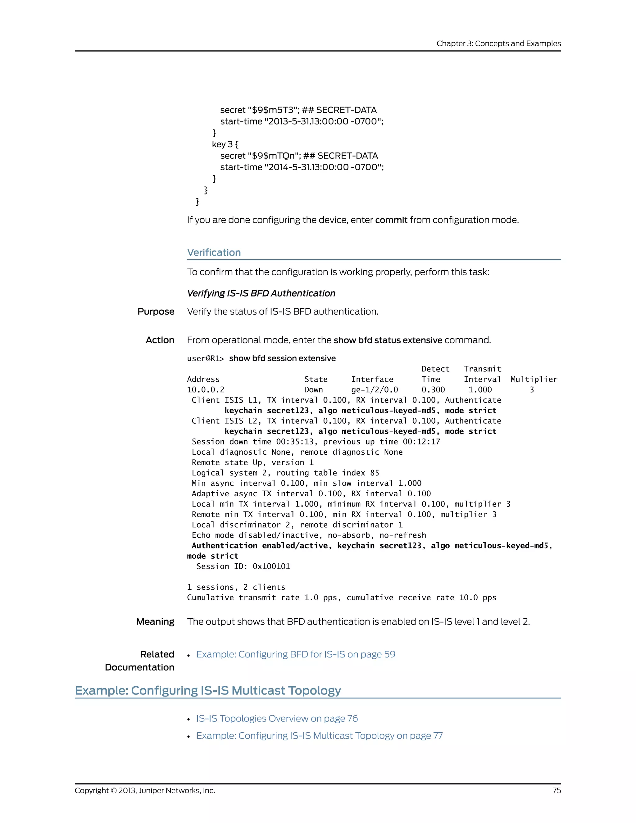
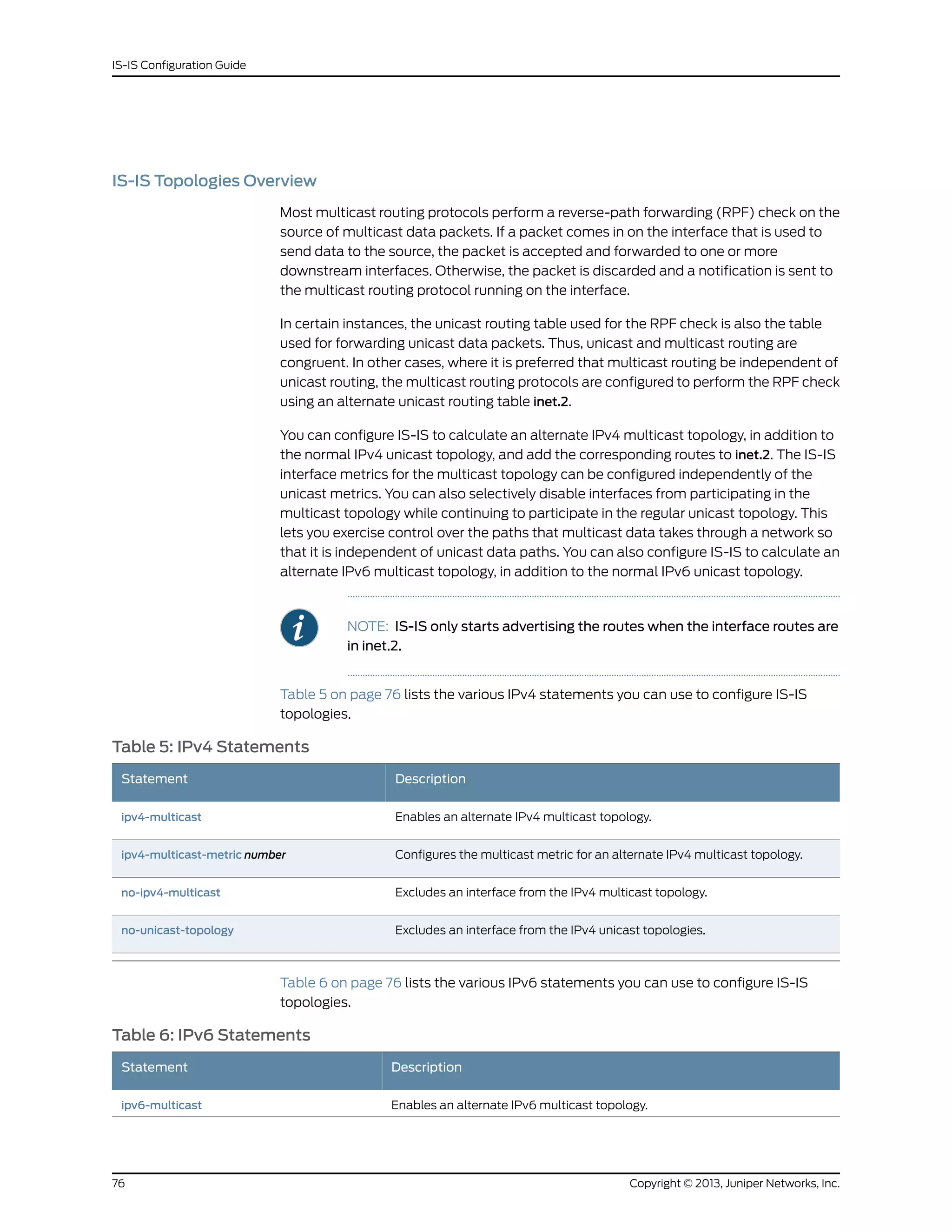
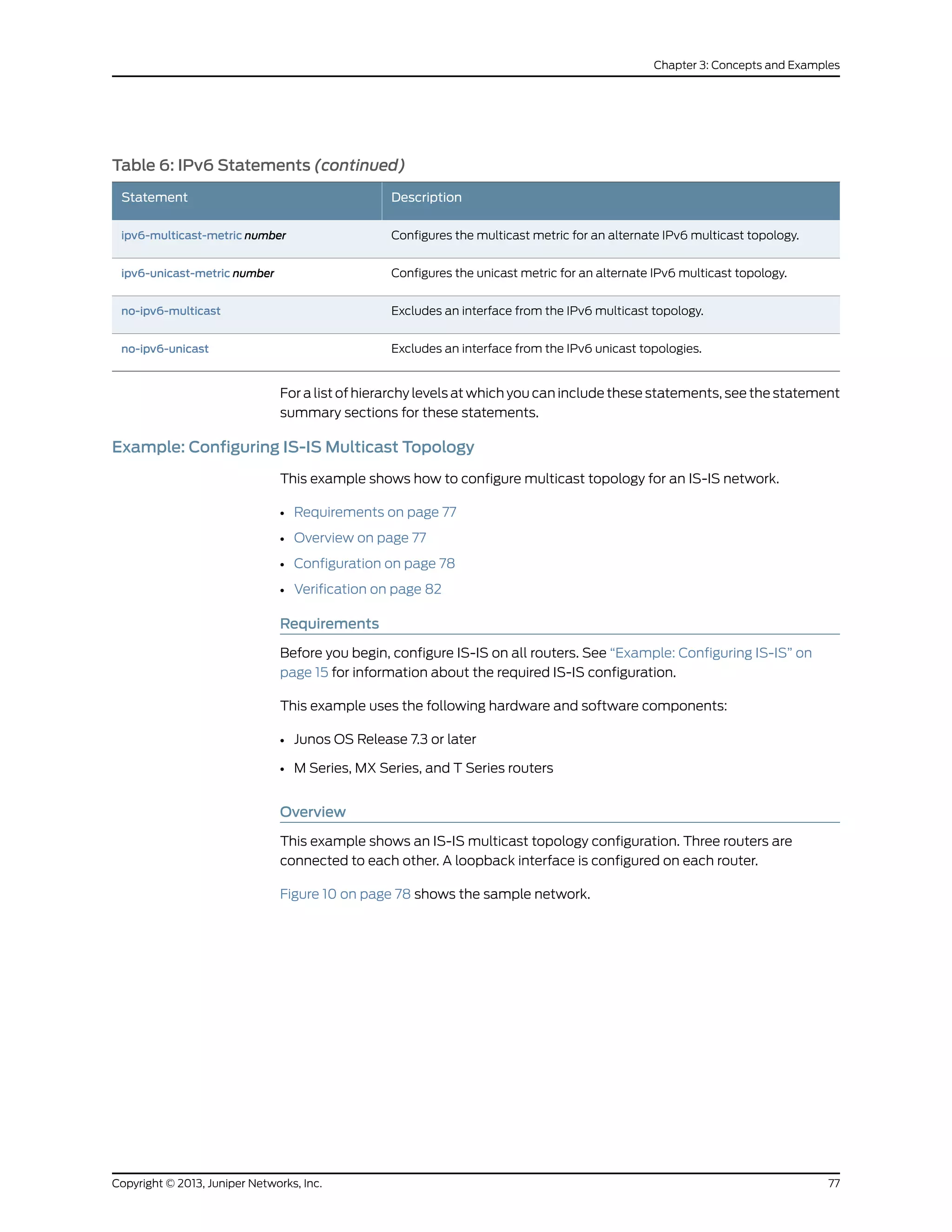
![Figure 10: Configuring IS-IS Multicast Topology
Configuration
CLI Quick
Configuration
To quickly configure this example, copy the following commands, paste them into a text
file, remove any line breaks, change any details necessary to match your network
configuration, and then copy and paste the commands into the CLI at the [edit] hierarchy
level.
Router R1
set protocols isis traceoptions file isis size 5m world-readable
set protocols isis traceoptions flag error
set protocols isis topologies ipv4-multicast
set protocols isis interface so-0/0/0 level 1 metric 15
set protocols isis interface so-0/0/0 level 1 ipv4-multicast-metric 18
set protocols isis interface so-0/0/0 level 2 metric 20
set protocols isis interface so-0/0/0 level 2 ipv4-multicast-metric 14
set protocols isis interface so-1/0/0 level 1 metric 13
set protocols isis interface so-1/0/0 level 1 ipv4-multicast-metric 12
set protocols isis interface so-1/0/0 level 2 metric 29
set protocols isis interface so-1/0/0 level 2 ipv4-multicast-metric 23
set protocols isis interface fxp0.0 disable
Router R2
set protocols isis traceoptions file isis size 5m world-readable
set protocols isis traceoptions flag error
set protocols isis topologies ipv4-multicast
set protocols isis interface so-0/0/0 level 1 metric 13
set protocols isis interface so-0/0/0 level 1 ipv4-multicast-metric 12
set protocols isis interface so-0/0/0 level 2 metric 29
Copyright © 2013, Juniper Networks, Inc.78
IS-IS Configuration Guide](https://image.slidesharecdn.com/config-guide-routing-is-is-151104131021-lva1-app6891/75/Juniper-MX-Config-guide-routing-is-is-98-2048.jpg)
![set protocols isis interface so-0/0/0 level 2 ipv4-multicast-metric 23
set protocols isis interface so-1/0/0 level 1 metric 14
set protocols isis interface so-1/0/0 level 1 ipv4-multicast-metric 18
set protocols isis interface so-1/0/0 level 2 metric 32
set protocols isis interface so-1/0/0 level 2 ipv4-multicast-metric 26
set protocols isis interface fxp0.0 disable
Router R3
set protocols isis traceoptions file isis size 5m world-readable
set protocols isis traceoptions flag error
set protocols isis topologies ipv4-multicast
set protocols isis interface so-0/0/0 level 1 metric 19
set protocols isis interface so-0/0/0 level 1 ipv4-multicast-metric 11
set protocols isis interface so-0/0/0 level 2 metric 27
set protocols isis interface so-0/0/0 level 2 ipv4-multicast-metric 21
set protocols isis interface so-1/0/0 level 1 metric 16
set protocols isis interface so-1/0/0 level 1 ipv4-multicast-metric 26
set protocols isis interface so-1/0/0 level 2 metric 30
set protocols isis interface so-1/0/0 level 2 ipv4-multicast-metric 20
set protocols isis interface fxp0.0 disable
The following example requires you to navigate various levels in the configuration
hierarchy. For information about navigating the CLI, see the CLI User Guide.
To configure IS-IS multicast topologies:
1. Enable the multicast topology for IS-IS by using the ipv4-multicast statement.
Routers R1, R2, and R3
[edit protocols isis]
user@host# set traceoptions file isis size 5m world-readable
user@host# set traceoptions flag error
user@host# set topologies ipv4-multicast
2. Enable multicast metrics on the first sonet Interface by using the ipv4-multicast-metric
statement.
Router R1
[edit protocols isis interface so-0/0/0 ]
user@R1# set level 1 metric 15
user@R1# set level 1 ipv4-multicast-metric 18
user@R1# set level 2 metric 20
user@R1# set level 2 ipv4-multicast-metric 14
Router R2
[edit protocols isis interface so-0/0/0]
user@R2# set level 1 metric 19
user@R2# set level 1 ipv4-multicast-metric 11
user@R2# set level 2 metric 27
user@R2# set level 2 ipv4-multicast-metric 21
Router R3
[edit protocols isis interface so-0/0/0]
user@R3# set level 1 metric 19
79Copyright © 2013, Juniper Networks, Inc.
Chapter 3: Concepts and Examples](https://image.slidesharecdn.com/config-guide-routing-is-is-151104131021-lva1-app6891/75/Juniper-MX-Config-guide-routing-is-is-99-2048.jpg)
![user@R3# set level 1 ipv4-multicast-metric 11
user@R3# set level 2 metric 27
user@R3# set level 2 ipv4-multicast-metric 21
3. Enable multicast metrics on a second sonet Interface by using the ipv4-multicast-metric
statement.
Router R1
[edit protocols isis interface so-1/0/0]
user@R1# set level 1 metric 13
user@R1# set level 1 ipv4-multicast-metric 12
user@R1# set level 2 metric 29
user@R1# set level 2 ipv4-multicast-metric 23
Router R2
[edit protocols isis interface so-1/0/0]
user@R2# set level 1 metric 14
user@R2# set level 1 ipv4-multicast-metric 18
user@R2# set level 2 metric 32
user@R2# set level 2 ipv4-multicast-metric 26
Router R3
[edit protocols isis interface so-1/0/0]
user@R3# set level 1 metric 16
user@R3# set level 1 ipv4-multicast-metric 26
user@R3# set level 2 metric 30
user@R3# set level 2 ipv4-multicast-metric 20
4. Disable the out-of-band management port, fxp0.
Routers R1, R2, and R3
[edit protocols isis]
user@host# set interface fxp0.0 disable
5. If you are done configuring the routers, commit the configuration.
Routers R1, R2, and R3
[edit]
user@host# commit
Results Confirm your configuration by using the show protocols isis statement.
Router R1
user@R1# show protocols isis
traceoptions {
file isis size 5m world-readable;
flag error;
}
topologies ipv4-multicast;
interface so-0/0/0 {
level 1 {
metric 15;
ipv4-multicast-metric 18;
}
level 2 {
Copyright © 2013, Juniper Networks, Inc.80
IS-IS Configuration Guide](https://image.slidesharecdn.com/config-guide-routing-is-is-151104131021-lva1-app6891/75/Juniper-MX-Config-guide-routing-is-is-100-2048.jpg)
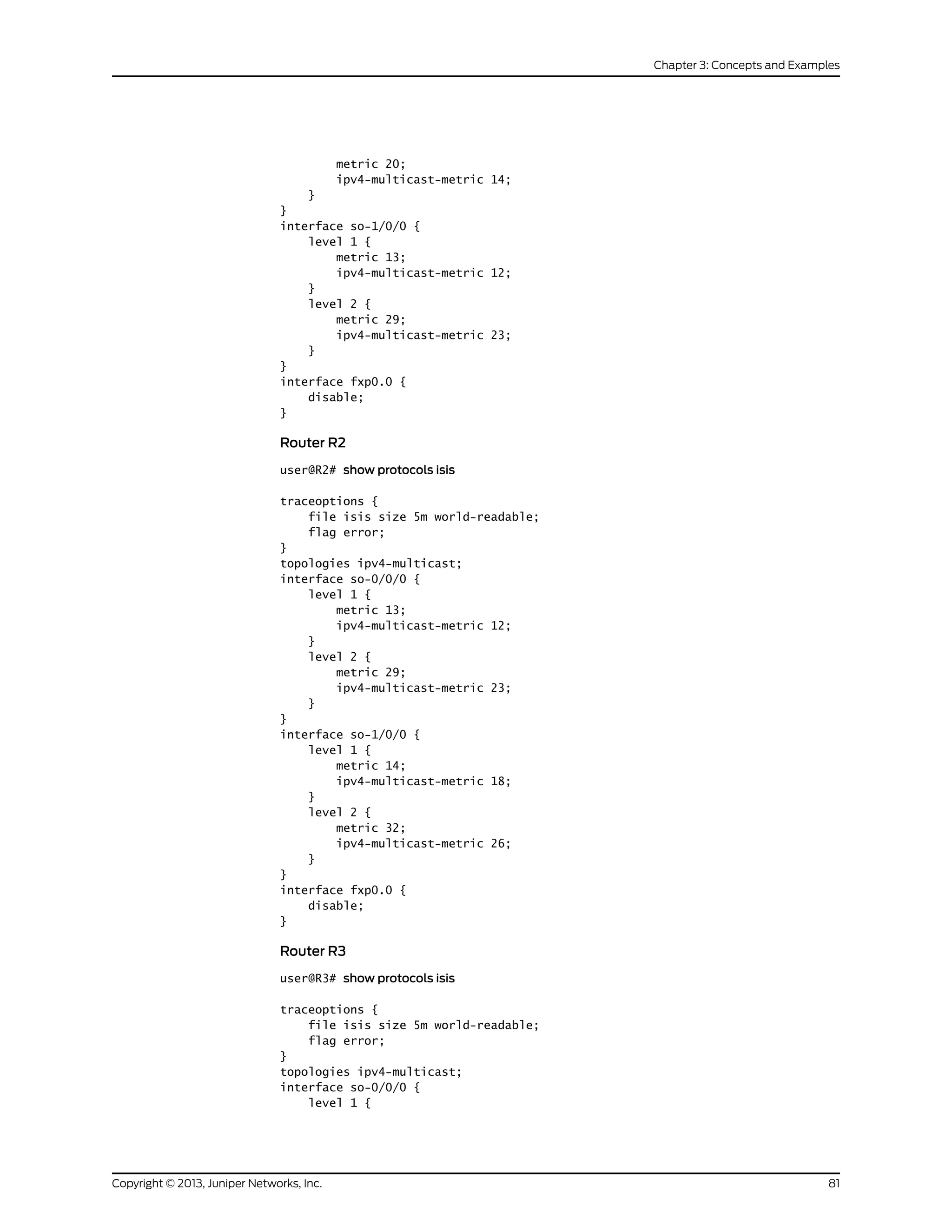
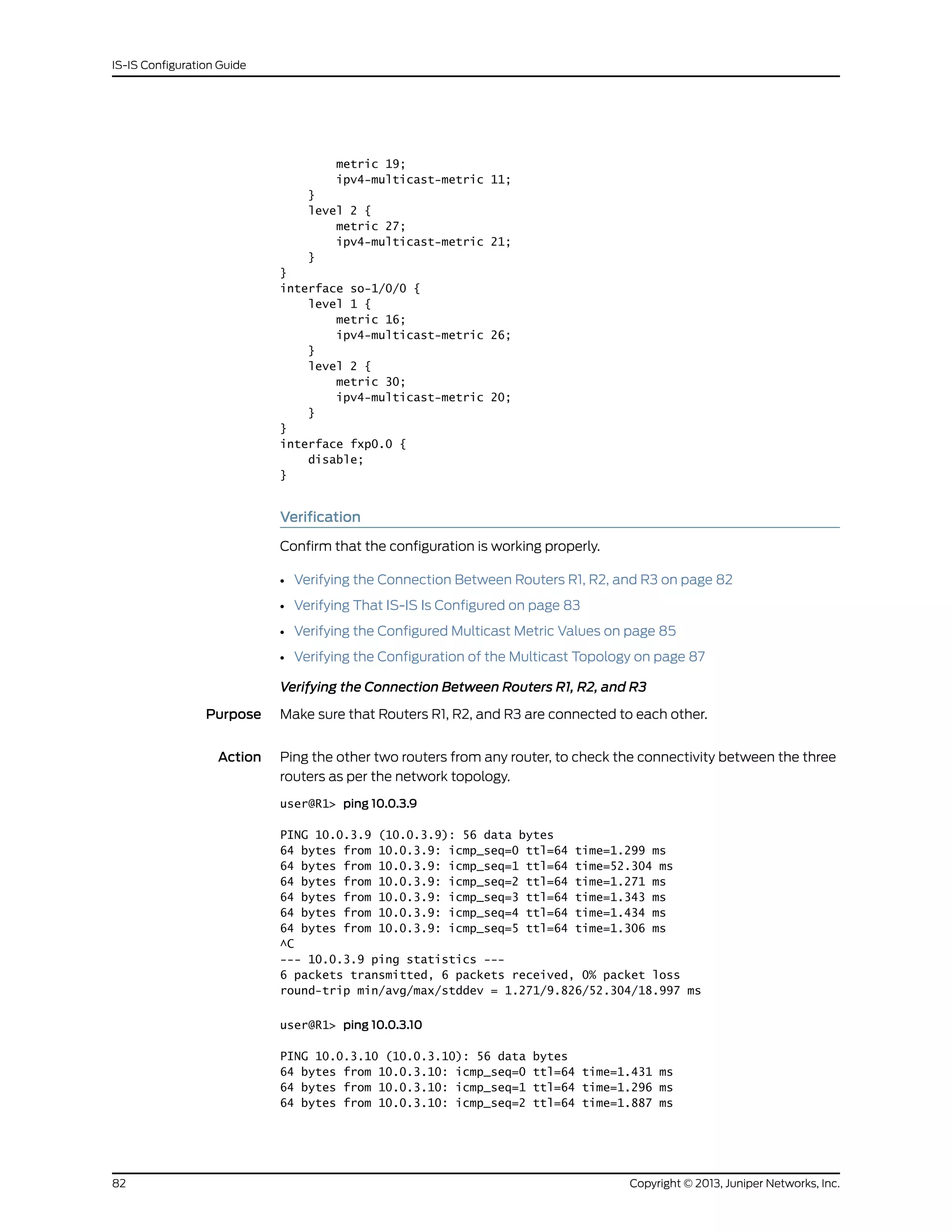
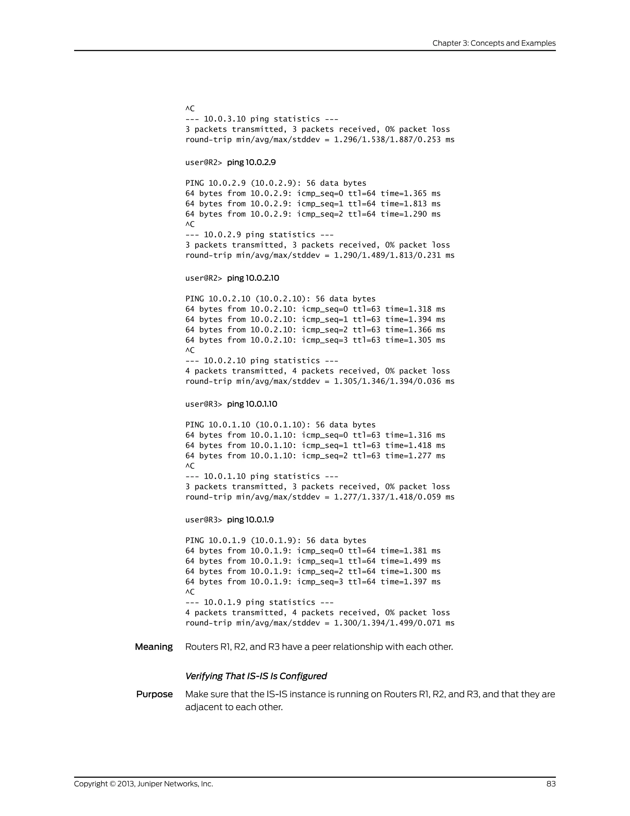
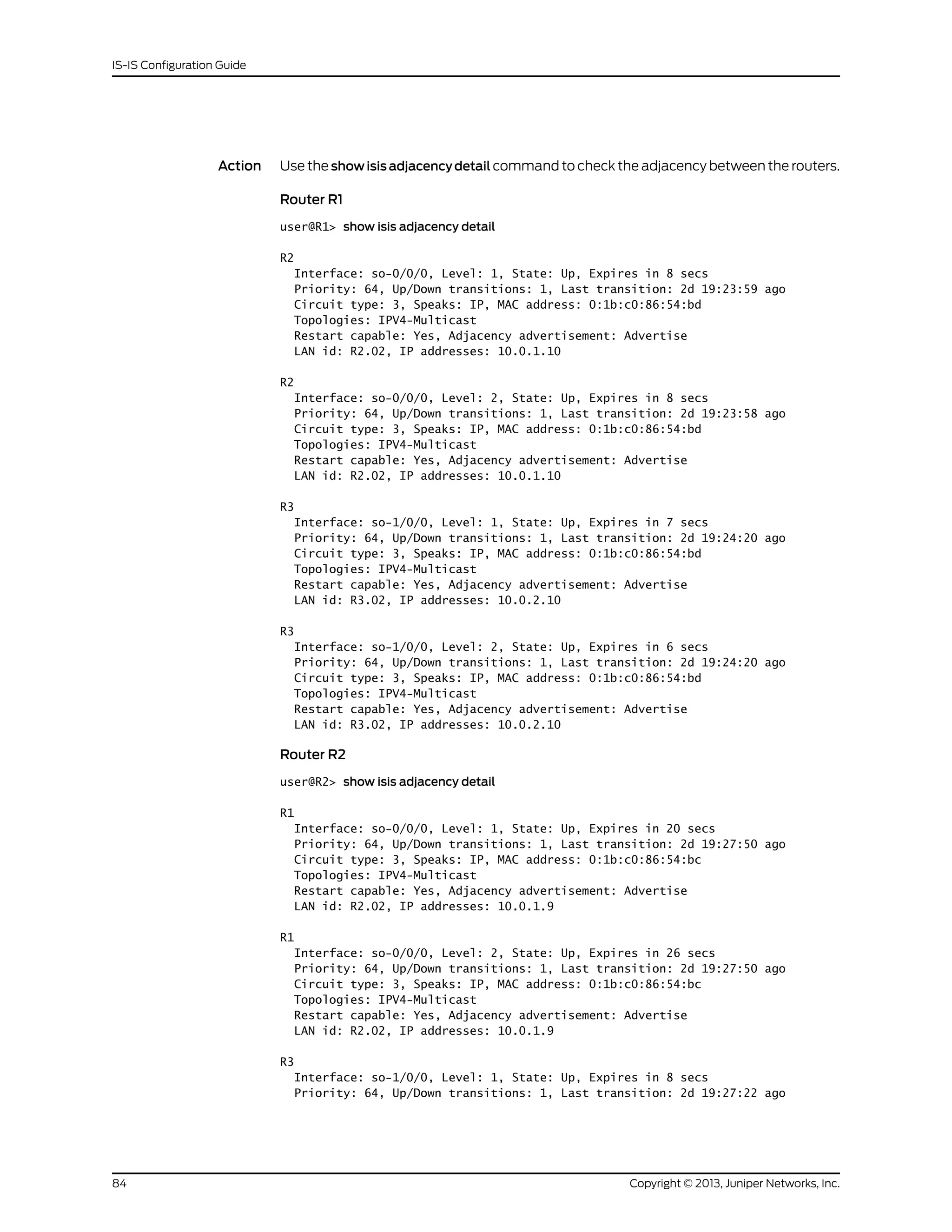
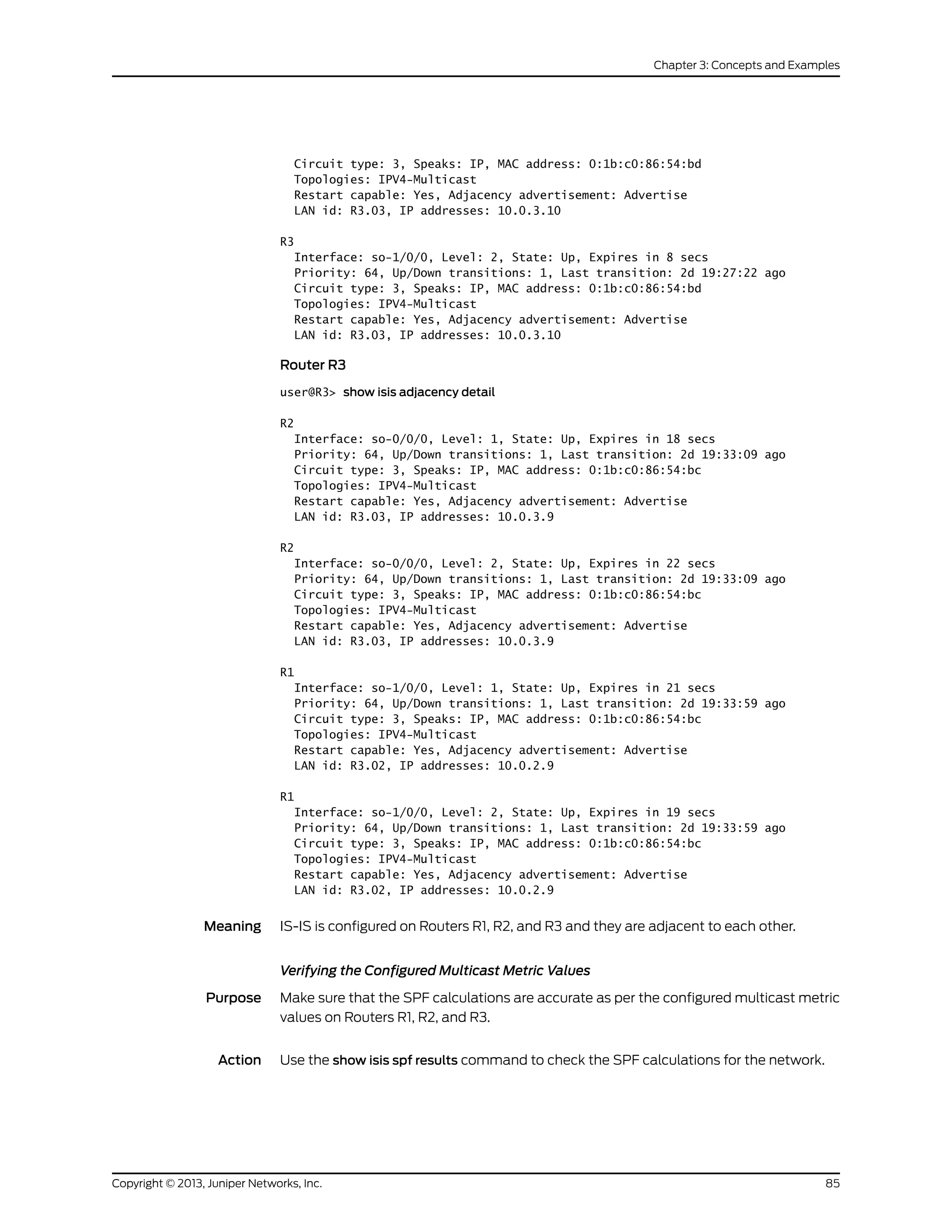
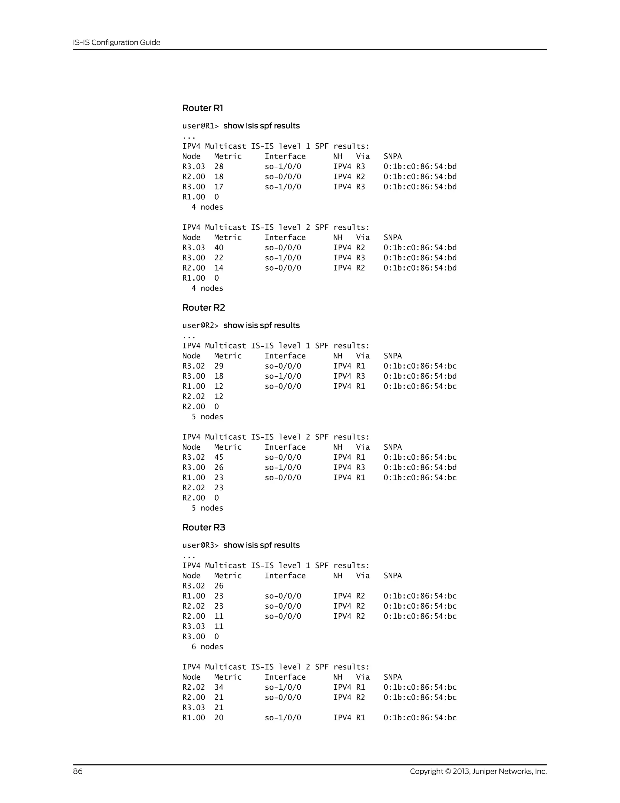
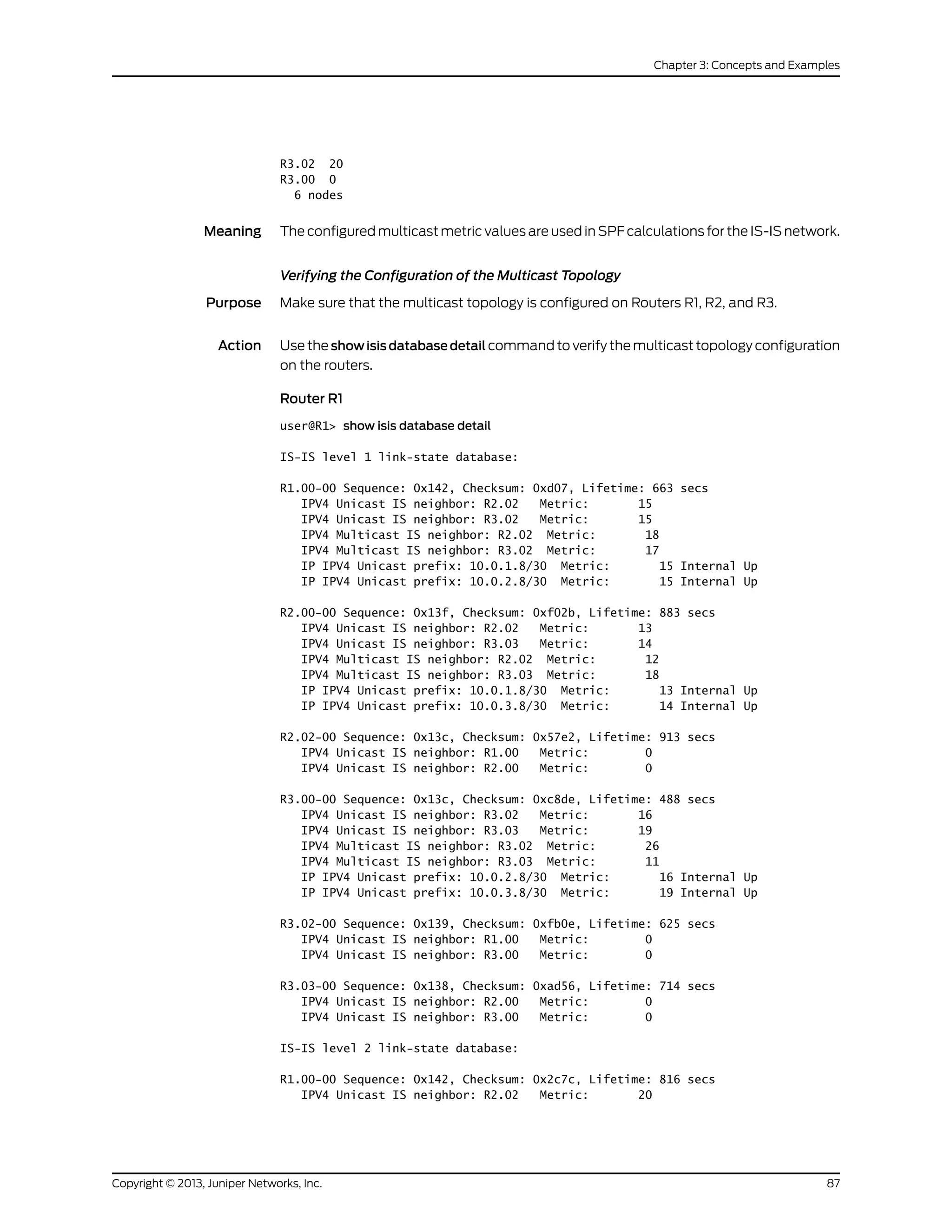
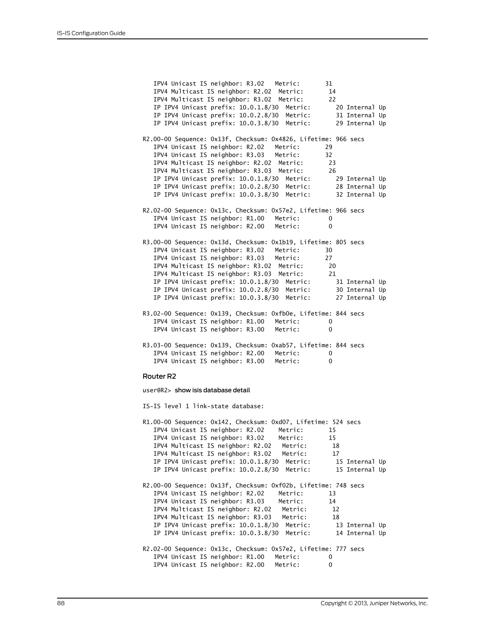
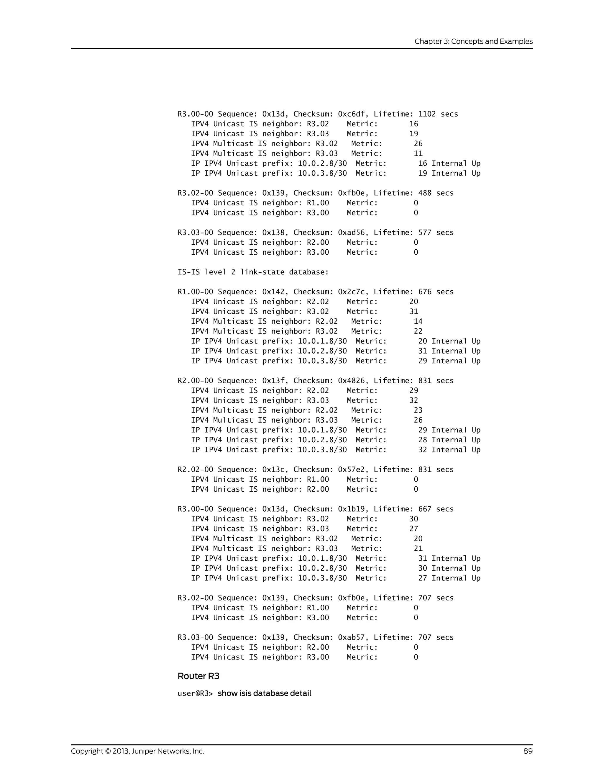
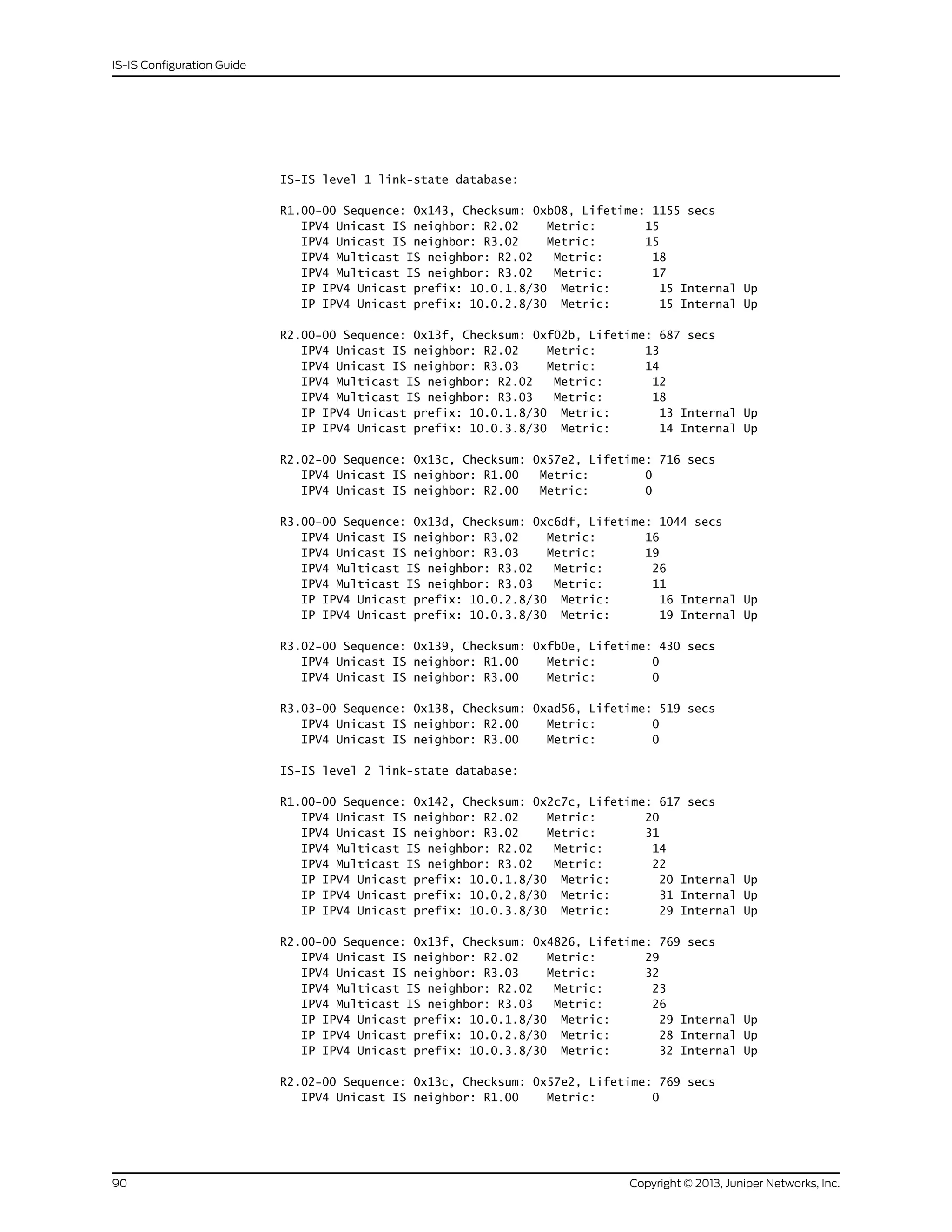
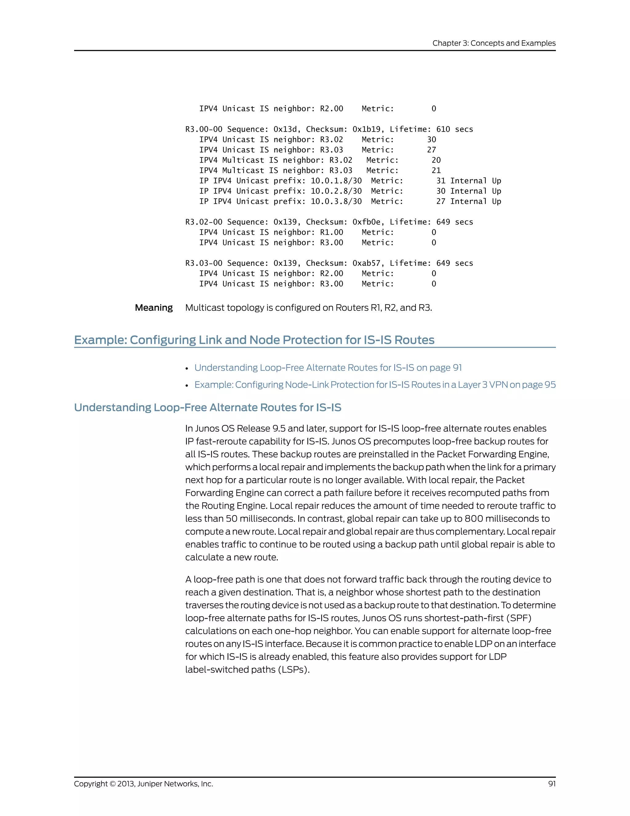
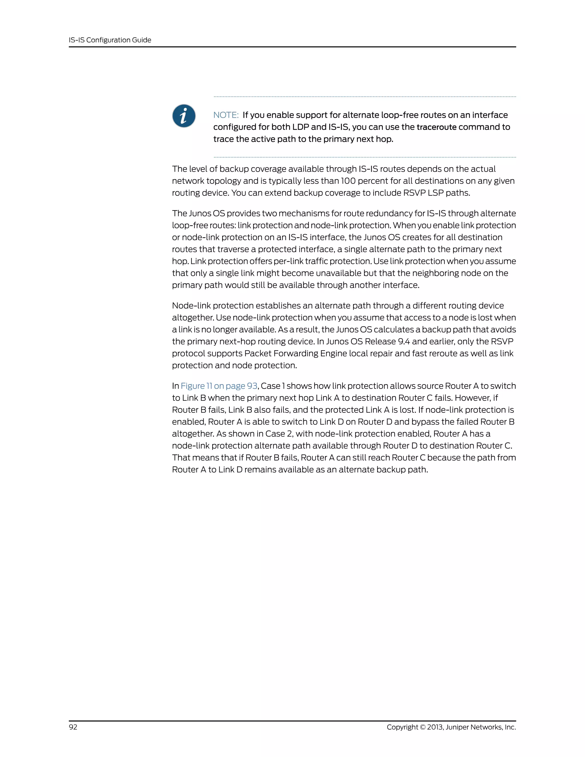
![Figure 11: Link Protection and Node-Link Protection Comparison for IS-IS
Routes
g017299
Node-link protection alternate pathCase 1
Link C
Link D Link E
X
Link A
Link B
Link protection alternate path
X
X
Link A
Link B
Case 2
Link D
Link C
Link E
A
D
B C
A
D
B C
Node-link protection alternate path
The Junos OS implementation of support for loop-free alternate paths for IS-IS routes
is based on the following standards:
• Internet draft draft-ietf-rtgwg-ipfrr-spec-base-12.txt, Basic Specification for IP
Fast-Reroute: Loop-free Alternates
• Internet draft draft-ietf-rtgwg-ipfrr-framework-06.txt, IP Fast Reroute Framework
Configuring Link Protection for IS-IS
You can configure link protection on any interface for which IS-IS is enabled. When you
enable link protection, the Junos OS creates one alternate path to the primary next hop
for all destination routes that traverse a protected interface. Link protection assumes
that only a single link becomes unavailable but that the neighboring node would still be
available through another interface.
NOTE: You must also configure a per-packet load-balancing routing policy
to ensure that the routing protocol process installs all the next hops for a
given route in the routing table.
To enable link protection, include the link-protection statement at the [edit protocols isis
interface interface-name] hierarchy level:
[edit]
protocols {
isis {
interface interface-name:
93Copyright © 2013, Juniper Networks, Inc.
Chapter 3: Concepts and Examples](https://image.slidesharecdn.com/config-guide-routing-is-is-151104131021-lva1-app6891/75/Juniper-MX-Config-guide-routing-is-is-113-2048.jpg)
![link-protection;
}
}
}
Configuring Node-Link Protection for IS-IS
You can configure node-link protection on any interface for which IS-IS is enabled.
Node-link protection establishes an alternate path through a different routing device
altogether for all destination routes that traverse a protected interface. Node-link
protection assumes that the entire routing device, or node, has failed. Junos OS therefore
calculates a backup path that avoids the primary next-hop routing device.
NOTE: You must also configure a per-packet load-balancing routing policy
to ensure that the routing protocol process installs all the next hops for a
given route in the routing table.
To enable node-link protection, include the node-link-protection statement at the [edit
protocols isis interface interface-name] hierarchy level:
[edit]
protocols {
isis {
interface interface-name:
node-link-protection;
}
}
}
Excluding an IS-IS Interface as a Backup for Protected Interfaces
By default, all IS-IS interfaces that belong to the master instance or a specific routing
instance are eligible as backup interfaces for protected interfaces. You can specify that
any IS-IS interface be excluded from functioning as a backup interface to protected
interfaces. To exclude an IS-IS interface as a backup interface, include the
no-eligible-backup statement at the [edit protocols isis interface interface-name] hierarchy
level:
[edit]
protocols {
isis {
interface interface-name {
no-eligible-backup;
}
}
}
Configuring RSVP Label-Switched Paths as Backup Paths for IS-IS
Relying on the shortest-path first (SPF) calculation of backup paths for one-hop neighbors
might result in less than 100 percent backup coverage for a specific network topology.
You can enhance coverage of IS-IS and LDP label-switched paths (LSPs) by configuring
RSVP LSPs as backup paths. To configure a specific RSVP LSP as a backup path, include
Copyright © 2013, Juniper Networks, Inc.94
IS-IS Configuration Guide](https://image.slidesharecdn.com/config-guide-routing-is-is-151104131021-lva1-app6891/75/Juniper-MX-Config-guide-routing-is-is-114-2048.jpg)
![the backup statement at the [edit protocols mpls label-switched-path lsp-name] hierarchy
level:
[edit]
protocols {
mpls {
label-switched-path lsp-name {
backup;
to ip-address;
}
}
}
When configuring an LSP, you must specify the IP address of the egress routing device
with the to statement. For detailed information about configuring LSPs and RSVP, see
the Junos OS MPLS Applications Configuration Guide.
Using Operational Mode Commands to Monitor Protected IS-IS Routes
You can issue operational mode commands that provide more details about your
link-protected and node-link-protected IS-IS routes. The following guidelines explain
the type of information available from the output of each command:
• showisisbackuplabel-switched-path—DisplayswhichMPLSLSPshavebeendesignated
as backup paths and the current status of those LSPs.
• show isis backup spf results—Displays SPF calculations for each neighbor for a given
destination. Indicates whether a specific interface or node has been designated as a
backup path and why. Use the no-coverage option to display only those nodes that do
not have backup coverage.
• show isis backup coverage—Displays the percentage of nodes and prefixes for each
type of address family that are protected.
• show isis interface detail—Displays the type of protection (link or node-link) applied
to each protected interface.
For more detailed information about these commands, see the Junos OS Operational
Mode Commands.
Example: Configuring Node-Link Protection for IS-IS Routes in a Layer 3 VPN
Node-link protection establishes an alternate path through a different routing device.
Use node-link protection when you assume that access to a node is lost when a link is
no longer available. The Junos OS calculates a backup path that avoids the primary
next-hop routing device.
• Requirements on page 96
• Overview on page 96
• Configuration on page 96
• Verification on page 103
95Copyright © 2013, Juniper Networks, Inc.
Chapter 3: Concepts and Examples](https://image.slidesharecdn.com/config-guide-routing-is-is-151104131021-lva1-app6891/75/Juniper-MX-Config-guide-routing-is-is-115-2048.jpg)
![Requirements
This example requires Junos OS Release 9.5 or later.
No special configuration beyond device initialization is required before configuring this
example.
Overview
In this example, core-facing interfaces are enabled for IS-IS level 2, LDP, and RSVP.
Node-link protection is enabled on all the core-facing interfaces, which means that if the
primary next hop for any destination that traverses the interfaces becomes unavailable,
the Junos OS uses a backup link that avoids the next-hop router altogether if necessary.
You also need to configure a routing policy that requires all traffic to use per-packet load
balancing in order to enable Packet Forwarding Engine local repair. With local repair, the
Packet Forwarding Engine can correct a path failure and implement a backup loop-free
alternate route before it receives recomputed paths from the Routing Engine.
Figure 12 on page 96 shows the topology used in this example.
Figure 12: IS-IS Node-Link Protection Topology
CE1 PE1 P1 P2 PE2
10.0.0.0/30 10.0.0.4/30 10.0.0.8/30 10.0.0.12/30
.1 .2 .5 .6 .9 .10 .13 .14
.21 .25
P3
10.0.0.20/30
10.0.0.24/30
.22 .30
.26
10.0.0.28/30
10.0.0.16/30
CE2
.29 .17
lo0,0 Addresses
CE1
PE1
P1
P2
P3
PE2
CE2
10.255.1.1
10.255.2.2
10.255.3.3
10.255.4.4
10.255.7.7
10.255.5.5
10.255.6.6
g041275
.18
On Device PE1, an RSVP LSP is configured as a backup paths for IS-IS. Relying on the
shortest-path first (SPF) calculation of backup paths for one-hop neighbors might result
in less than 100 percent backup coverage for a specific network topology. You can enhance
coverage of IS-IS and LDP LSPs by configuring RSVP LSPs as backup paths. To configure
a specific RSVP LSP as a backup path, include the backup statement at the [edit protocols
mpls label-switched-path lsp-name] hierarchy level.
“CLI Quick Configuration” on page 96 shows the configuration for all of the devices in
Figure 12 on page 96. The section “Step-by-Step Procedure” on page 100 describes the
steps on Device P1.
Configuration
CLI Quick
Configuration
To quickly configure this example, copy the following commands, paste them into a text
file, remove any line breaks, change any details necessary to match your network
configuration, and then copy and paste the commands into the CLI at the [edit] hierarchy
level.
Device CE1 set interfaces fe-1/2/0 unit 0 family inet address 10.0.0.1/30
Copyright © 2013, Juniper Networks, Inc.96
IS-IS Configuration Guide](https://image.slidesharecdn.com/config-guide-routing-is-is-151104131021-lva1-app6891/75/Juniper-MX-Config-guide-routing-is-is-116-2048.jpg)
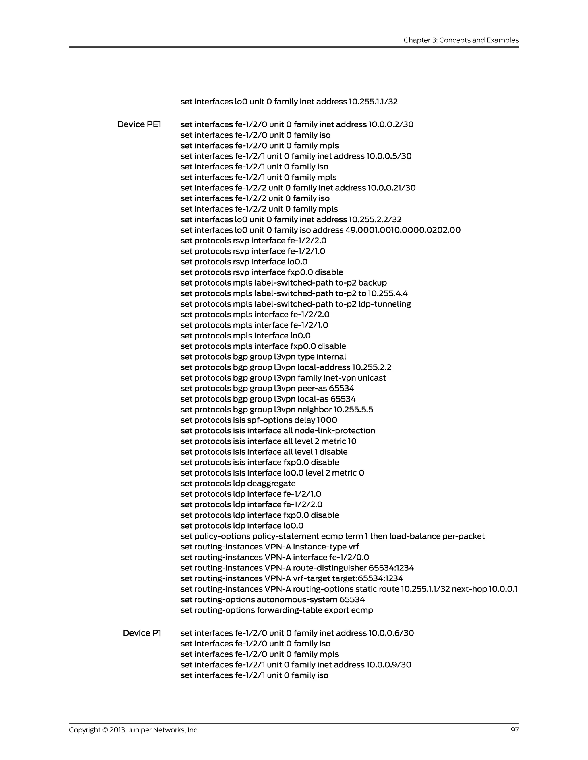
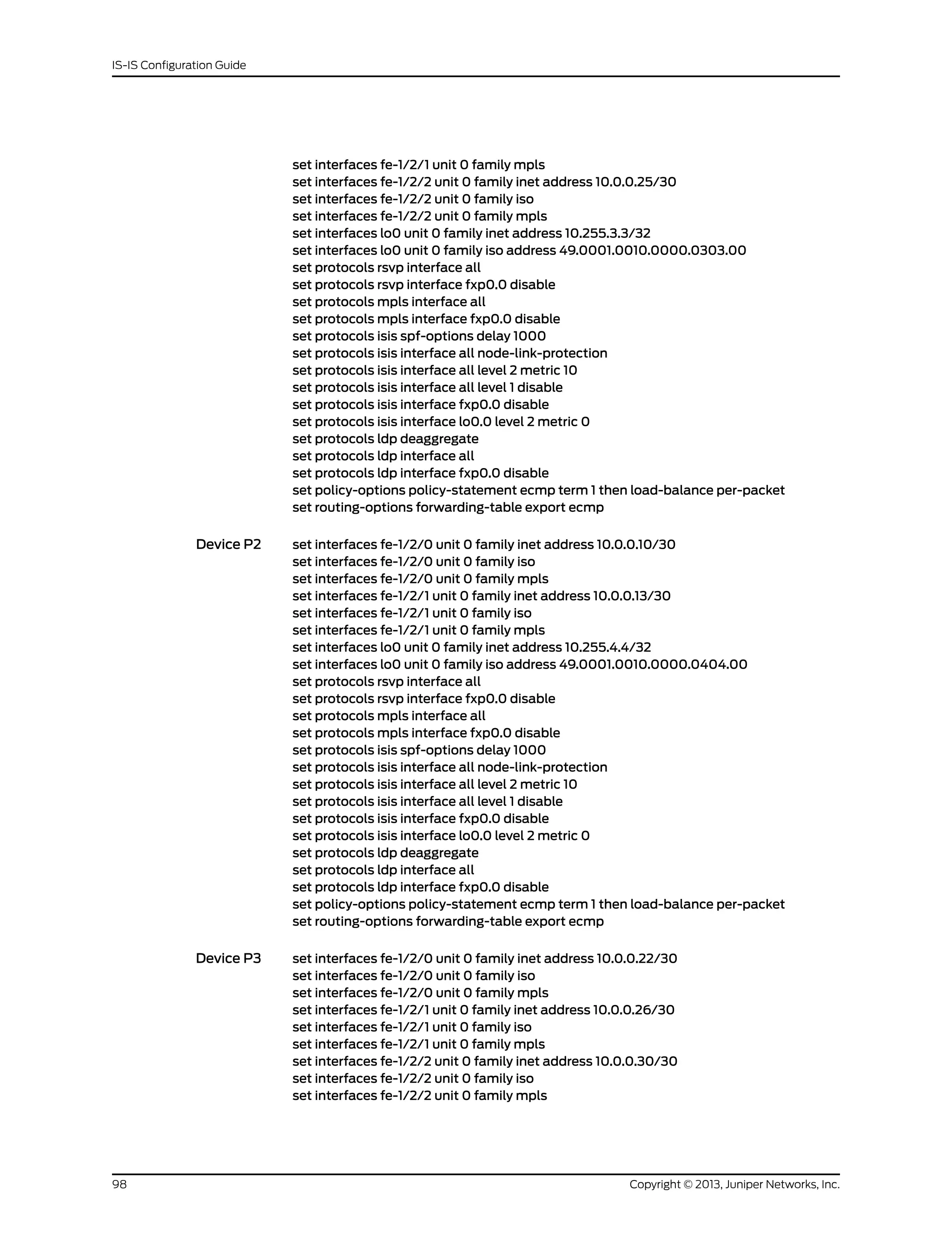
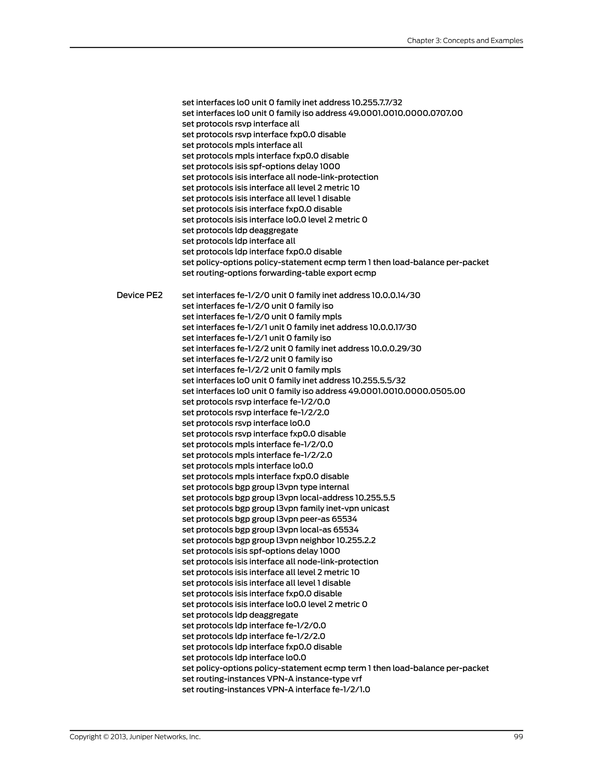
![set routing-instances VPN-A route-distinguisher 65534:1234
set routing-instances VPN-A vrf-target target:65534:1234
set routing-instances VPN-A routing-options static route 10.255.1.1/32 next-hop 10.0.0.18
set routing-options autonomous-system 65534
set routing-options forwarding-table export ecmp
Device CE2 set interfaces fe-1/2/0 unit 0 family inet address 10.0.0.18/30
set interfaces lo0 unit 0 family inet address 10.255.6.6/32
Step-by-Step
Procedure
The following example requires you to navigate various levels in the configuration
hierarchy. For information about navigating the CLI, see Using the CLI Editor in
Configuration Mode in the CLI User Guide.
To configure multi-level IS-IS:
1. Configure the interfaces.
Enable IS-IS and MPLS.
[edit interfaces]
user@P1# set fe-1/2/0 unit 0 family inet address 10.0.0.6/30
user@P1# set fe-1/2/0 unit 0 family iso
user@P1# set fe-1/2/0 unit 0 family mpls
user@P1# set fe-1/2/1 unit 0 family inet address 10.0.0.9/30
user@P1# set fe-1/2/1 unit 0 family iso
user@P1# set fe-1/2/1 unit 0 family mpls
user@P1# set fe-1/2/2 unit 0 family inet address 10.0.0.25/30
user@P1# set fe-1/2/2 unit 0 family iso
user@P1# set fe-1/2/2 unit 0 family mpls
user@P1# set lo0 unit 0 family inet address 10.255.3.3/32
user@P1# set lo0 unit 0 family iso address 49.0001.0010.0000.0303.00
2. Configure the IS-IS interfaces for Level 2, and configure MPLS to use both RSVP
and LDP label-switched paths (LSPs).
Enable IS-ISnode-link protection,which also automatically extendsbackupcoverage
to all LDP LSPs.
Optionally, configure a 1000-millisecond time interval between the detection of a
topology change and when the SPF algorithm runs.
For LDP, enable forwarding equivalence class (FEC) deaggregation, which results
in faster global convergence.
[edit protocols]
user@P1# set rsvp interface all
user@P1# set rsvp interface fxp0.0 disable
user@P1# set mpls interface all
user@P1# set mpls interface fxp0.0 disable
user@P1# set isis spf-options delay 1000
Copyright © 2013, Juniper Networks, Inc.100
IS-IS Configuration Guide](https://image.slidesharecdn.com/config-guide-routing-is-is-151104131021-lva1-app6891/75/Juniper-MX-Config-guide-routing-is-is-120-2048.jpg)
![user@P1# set isis interface all node-link-protection
user@P1# set isis interface all level 2 metric 10
user@P1# set isis interface all level 1 disable
user@P1# set isis interface fxp0.0 disable
user@P1# set isis interface lo0.0 level 2 metric 0
user@P1# set ldp deaggregate
user@P1# set ldp interface all
user@P1# set ldp interface fxp0.0 disable
3. To enable Packet Forwarding Engine local repair, establish a policy that forces the
routing protocol process to install all the next hops for a given route.
This policy ensures that the backup route is installed in the forwarding table used
by the Packet Forwarding Engine to forward traffic to a given destination. After this
policy is configured, export it to the forwarding table of the local router with the
export statement.
[edit policy-options policy-statement ecmp term 1]
user@P1# set then load-balance per-packet
[edit routing-options forwarding-table]
user@P1# set export ecmp
Results From configuration mode, confirm your configuration by entering the show interfaces,
show protocols, show policy-options, and show routing-options commands. If the output
does not display the intended configuration, repeat the configuration instructions in this
example to correct it.
user@P1# show interfaces
fe-1/2/0 {
unit 0 {
family inet {
address 10.0.0.6/30;
}
family iso;
family mpls;
}
}
fe-1/2/1 {
unit 0 {
family inet {
address 10.0.0.9/30;
}
family iso;
family mpls;
}
}
fe-1/2/2 {
unit 0 {
family inet {
address 10.0.0.25/30;
}
family iso;
family mpls;
101Copyright © 2013, Juniper Networks, Inc.
Chapter 3: Concepts and Examples](https://image.slidesharecdn.com/config-guide-routing-is-is-151104131021-lva1-app6891/75/Juniper-MX-Config-guide-routing-is-is-121-2048.jpg)
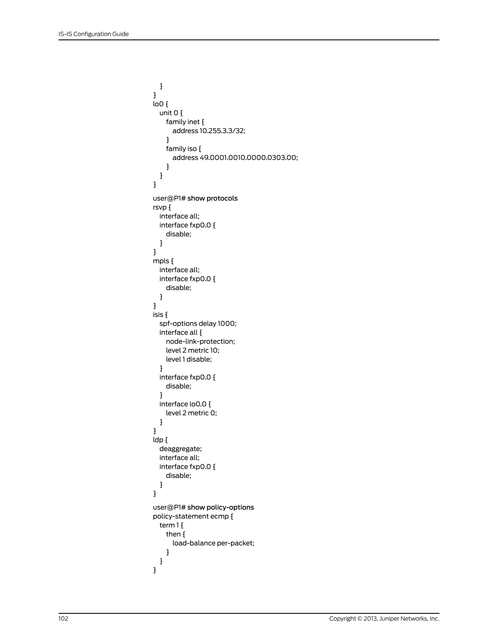
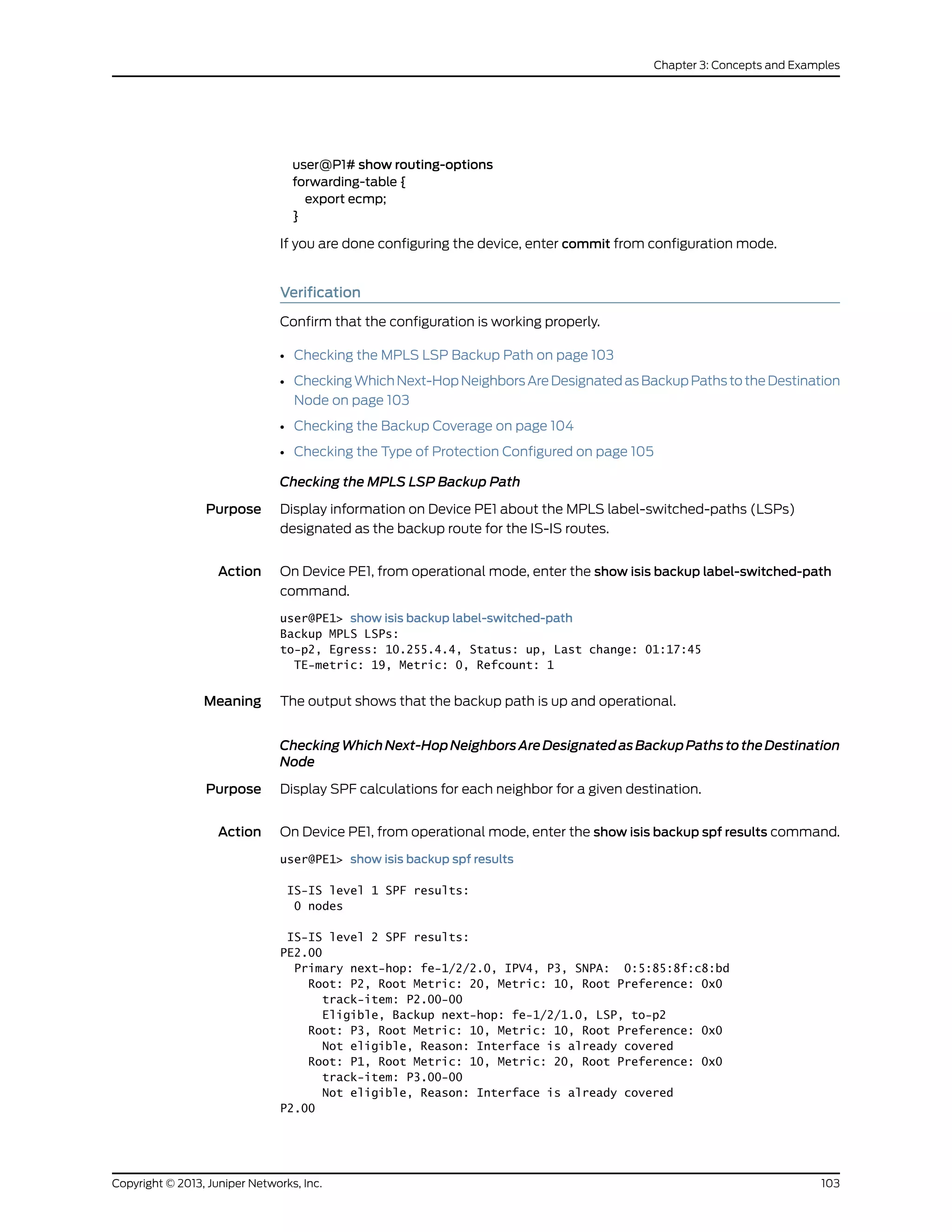
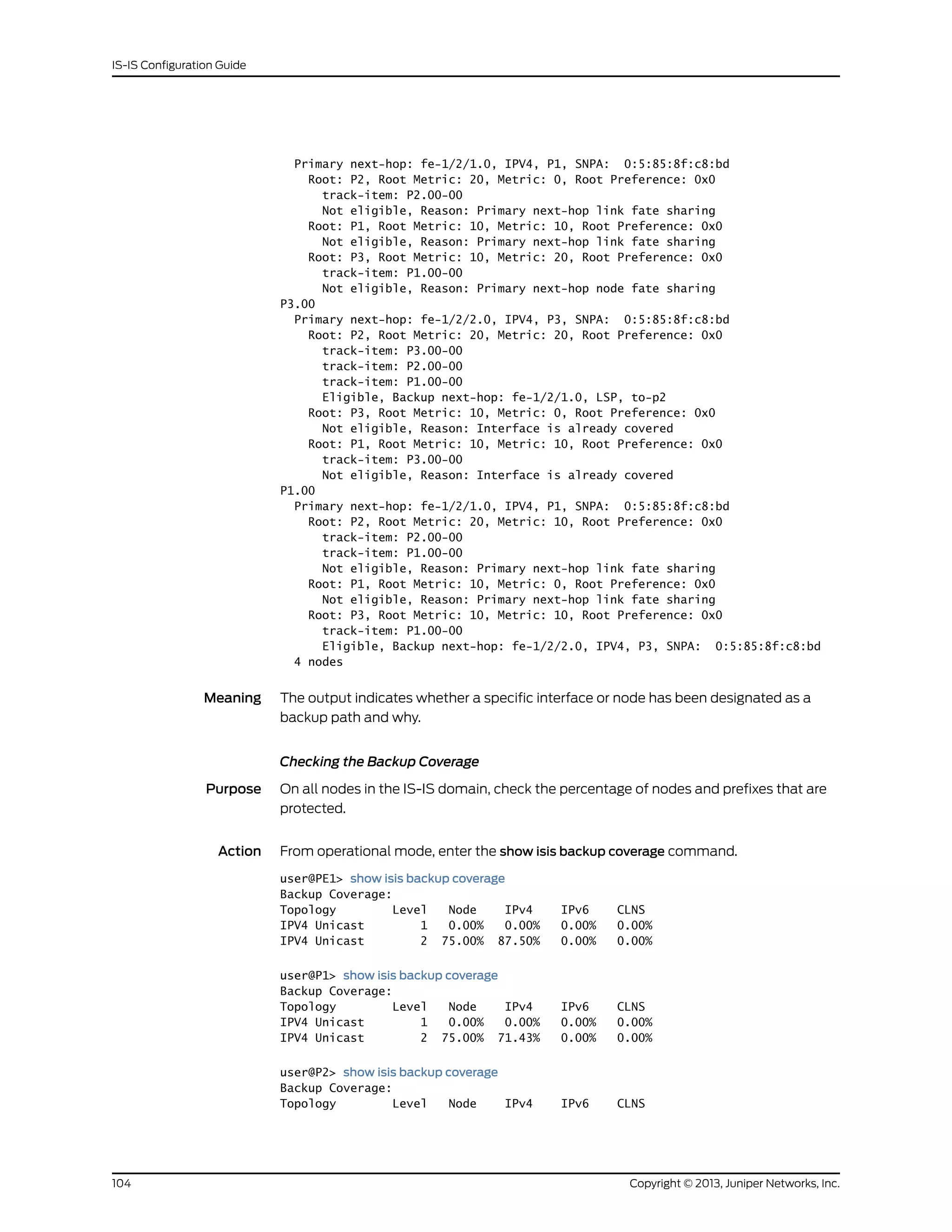
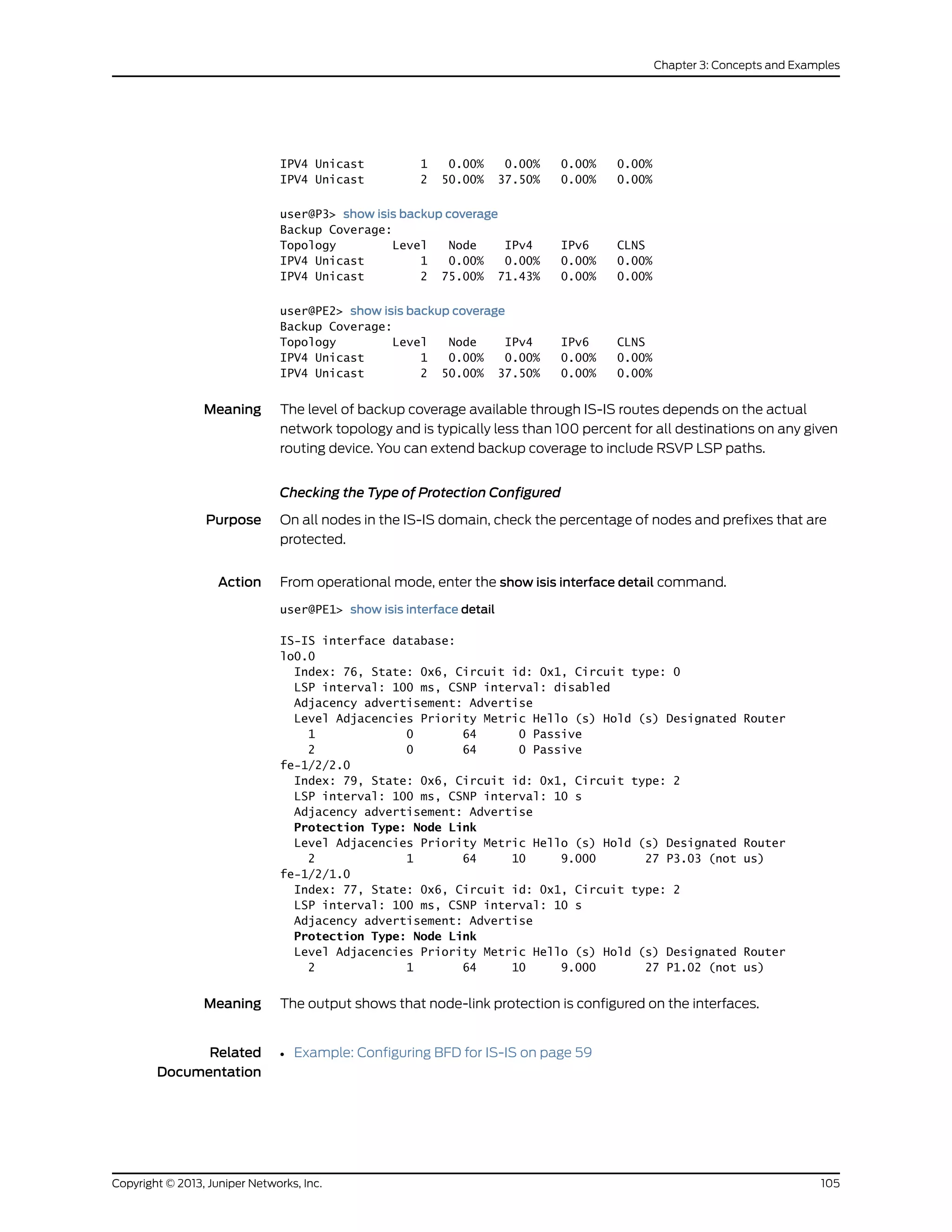
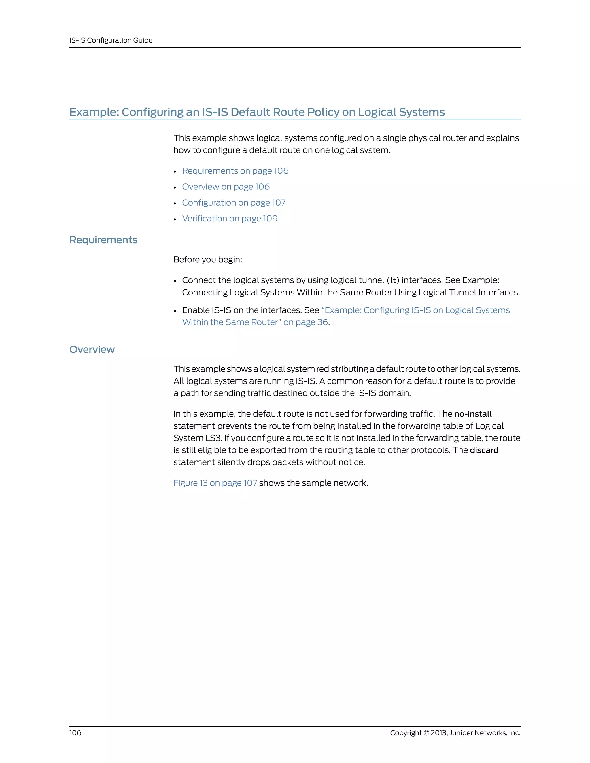
![Figure 13: IS-IS with a Default Route to an ISP
Configuration
CLI Quick
Configuration
To quickly configure this example, copy the following commands, paste them into a text
file, remove any line breaks, change any details necessary to match your network
configuration, and then copy and paste the commands into the CLI at the [edit] hierarchy
level.
set logical-systems LS3 routing-options static route 0.0.0.0/0 discard
set logical-systems LS3 routing-options static route 0.0.0.0/0 no-install
set logical-systems LS3 policy-options policy-statement isis-default from protocol static
set logical-systems LS3 policy-options policy-statement isis-default from route-filter
0.0.0.0/0 exact
set logical-systems LS3 policy-options policy-statement isis-default then accept
set logical-systems LS3 protocols isis export isis-default
Step-by-Step
Procedure
The following example requires you to navigate various levels in the configuration
hierarchy. For information about navigating the CLI, see Using the CLI Editor in
Configuration Mode in the CLI User Guide.
To configure an IS-IS default route policy on logical systems:
1. Configure the default route on Logical System LS3.
[edit logical-systems LS3 routing-options]
user@host# set static route 0.0.0.0/0 discard
user@host# set static route 0.0.0.0/0 no-install
2. Configure the default route policy on Logical System LS3.
[edit logical-systems LS3 policy-options]
user@host# set policy-statement isis-default from protocol static
user@host# set policy-statement isis-default from route-filter 0.0.0.0/0 exact
user@host# set policy-statement isis-default then accept
107Copyright © 2013, Juniper Networks, Inc.
Chapter 3: Concepts and Examples](https://image.slidesharecdn.com/config-guide-routing-is-is-151104131021-lva1-app6891/75/Juniper-MX-Config-guide-routing-is-is-127-2048.jpg)
![3. Apply the export policy to IS-IS on Logical System LS3.
[edit logical-systems LS3 protocols isis]
user@host# set export isis-default
4. If you are done configuring the device, commit the configuration.
[edit]
user@host# commit
Results
Confirm your configuration by issuing the show logical-systems LS3 command.
user@host# show logical-systems LS3
LS3 {
interfaces {
lt-1/2/0 {
unit 3 {
description LS3->LS2;
encapsulation ethernet;
peer-unit 4;
family inet {
address 10.0.2.1/30;
}
family iso;
}
unit 5 {
description LS3->LS1;
encapsulation ethernet;
peer-unit 0;
family inet {
address 10.0.1.1/30;
}
family iso;
}
}
lo0 {
unit 3 {
family iso {
address 49.0001.1234.1600.2231.00;
}
}
}
}
protocols {
isis {
export isis-default;
interface lt-1/2/0.3;
interface lt-1/2/0.5;
interface lo0.3 {
passive;
}
}
}
policy-options {
policy-statement isis-default {
from {
protocol static;
route-filter 0.0.0.0/0 exact;
Copyright © 2013, Juniper Networks, Inc.108
IS-IS Configuration Guide](https://image.slidesharecdn.com/config-guide-routing-is-is-151104131021-lva1-app6891/75/Juniper-MX-Config-guide-routing-is-is-128-2048.jpg)
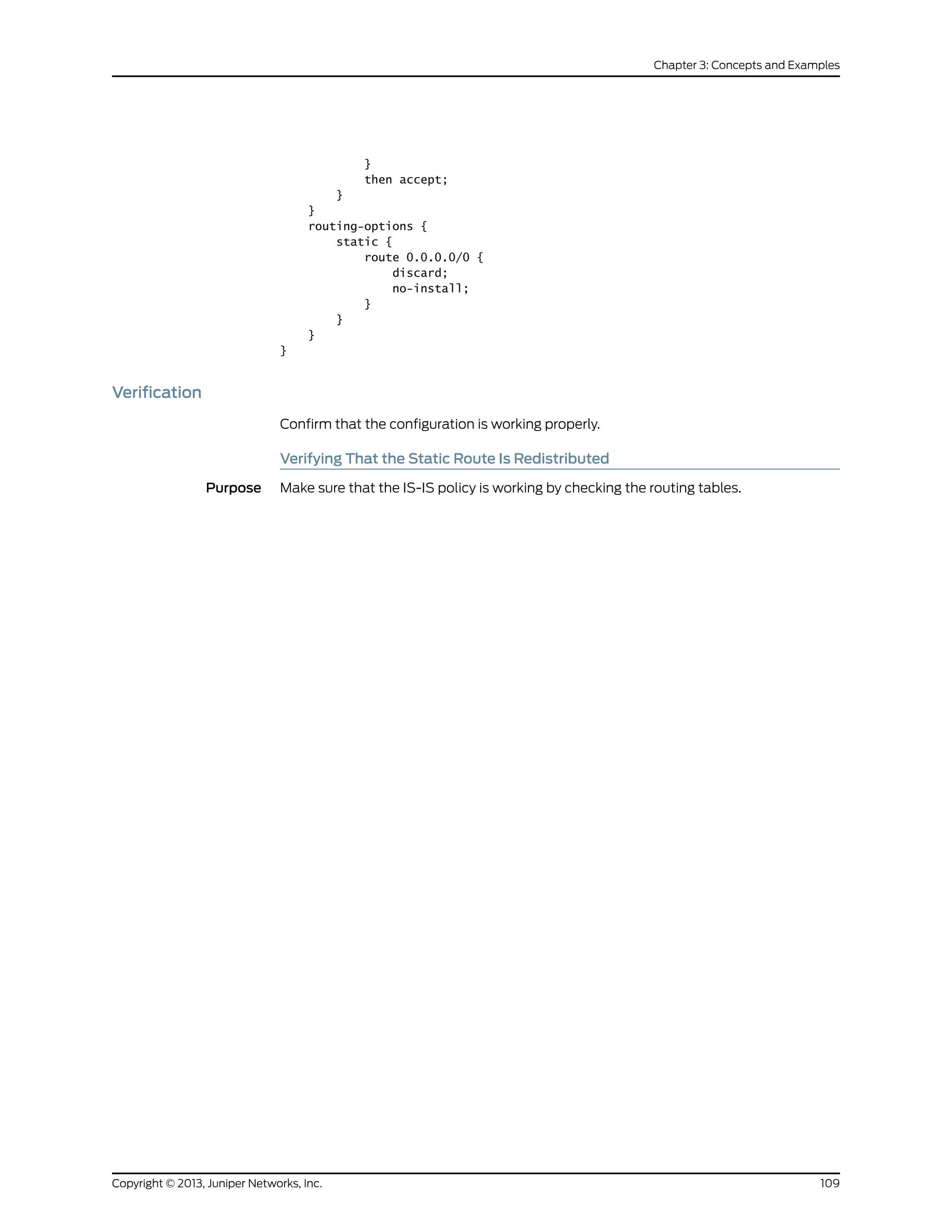
![Action user@host> show route logical-system LS3
inet.0: 6 destinations, 6 routes (6 active, 0 holddown, 0 hidden)
+ = Active Route, - = Last Active, * = Both
0.0.0.0/0 *[Static/5] 00:00:45
Discard
10.0.0.0/30 *[IS-IS/15] 1w0d 10:14:14, metric 20
to 10.0.2.2 via lt-1/2/0.3
> to 10.0.1.2 via lt-1/2/0.5
10.0.1.0/30 *[Direct/0] 1w0d 10:15:18
> via lt-1/2/0.5
10.0.1.1/32 *[Local/0] 1w0d 10:15:18
Local via lt-1/2/0.5
10.0.2.0/30 *[Direct/0] 1w0d 10:15:18
> via lt-1/2/0.3
10.0.2.1/32 *[Local/0] 1w0d 10:15:18
Local via lt-1/2/0.3
iso.0: 1 destinations, 1 routes (1 active, 0 holddown, 0 hidden)
+ = Active Route, - = Last Active, * = Both
49.0001.1234.1600.2231/72
*[Direct/0] 1w0d 10:17:19
> via lo0.3
user@host> show route logical-system LS2
inet.0: 6 destinations, 6 routes (6 active, 0 holddown, 0 hidden)
+ = Active Route, - = Last Active, * = Both
0.0.0.0/0 *[IS-IS/160] 00:01:38, metric 10
> to 10.0.2.1 via lt-1/2/0.4
10.0.0.0/30 *[Direct/0] 1w0d 10:16:11
> via lt-1/2/0.1
10.0.0.2/32 *[Local/0] 1w0d 10:16:11
Local via lt-1/2/0.1
10.0.1.0/30 *[IS-IS/15] 1w0d 10:15:07, metric 20
> to 10.0.0.1 via lt-1/2/0.1
to 10.0.2.1 via lt-1/2/0.4
10.0.2.0/30 *[Direct/0] 1w0d 10:16:11
> via lt-1/2/0.4
10.0.2.2/32 *[Local/0] 1w0d 10:16:11
Local via lt-1/2/0.4
iso.0: 1 destinations, 1 routes (1 active, 0 holddown, 0 hidden)
+ = Active Route, - = Last Active, * = Both
49.0001.1720.1600.2002/72
*[Direct/0] 1w0d 10:18:12
> via lo0.2
user@host> show route logical-system LS1
inet.0: 6 destinations, 6 routes (6 active, 0 holddown, 0 hidden)
+ = Active Route, - = Last Active, * = Both
0.0.0.0/0 *[IS-IS/160] 00:02:01, metric 10
> to 10.0.1.1 via lt-1/2/0.0
10.0.0.0/30 *[Direct/0] 1w0d 10:16:34
> via lt-1/2/0.2
10.0.0.1/32 *[Local/0] 1w0d 10:16:34
Local via lt-1/2/0.2
10.0.1.0/30 *[Direct/0] 1w0d 10:16:34
Copyright © 2013, Juniper Networks, Inc.110
IS-IS Configuration Guide](https://image.slidesharecdn.com/config-guide-routing-is-is-151104131021-lva1-app6891/75/Juniper-MX-Config-guide-routing-is-is-130-2048.jpg)
![> via lt-1/2/0.0
10.0.1.2/32 *[Local/0] 1w0d 10:16:34
Local via lt-1/2/0.0
10.0.2.0/30 *[IS-IS/15] 1w0d 10:15:55, metric 20
to 10.0.1.1 via lt-1/2/0.0
> to 10.0.0.2 via lt-1/2/0.2
iso.0: 1 destinations, 1 routes (1 active, 0 holddown, 0 hidden)
+ = Active Route, - = Last Active, * = Both
49.0001.1720.1600.1001/72
*[Direct/0] 1w0d 10:18:35
> via lo0.1
Meaning The routing table on Logical System LS3 contains the default 0.0.0.0/0 route from
protocol Static. The routing tables on Logical System LS1 and Logical System LS2 contain
the default 0.0.0.0/0 route from protocol IS-IS. If Logical System LS1 and Logical System
LS2 receive packets destined for networks not specified in their routing tables, those
packets will be sent to Logical System LS3 for further processing. This configuration
assumes that Logical System LS3 has a connection to an ISP or another external network.
Related
Documentation
Example: Creating an Interface on a Logical System•
Example: Configuring IS-IS for CLNS
• Understanding IS-IS for CLNS on page 111
• Example: Configuring IS-IS for CLNS on page 111
Understanding IS-IS for CLNS
Intermediate System-to-Intermediate System (IS-IS) extensions provide the basic interior
gateway protocol (IGP) support for collecting intradomain routing information for
Connectionless Network Service (CLNS) destinations within a CLNS network. Routers
that learn host addresses through End System-to-Intermediate System (ES-IS) can
advertise the addresses to other routers (intermediate systems) by using IS-IS.
For more information about IS-IS, see the ISO 10589 standard.
Example: Configuring IS-IS for CLNS
This example shows how to create a routing instance and enable IS-IS protocol on all
interfaces.
• Requirements on page 112
• Overview on page 112
• Configuration on page 112
• Verification on page 113
111Copyright © 2013, Juniper Networks, Inc.
Chapter 3: Concepts and Examples](https://image.slidesharecdn.com/config-guide-routing-is-is-151104131021-lva1-app6891/75/Juniper-MX-Config-guide-routing-is-is-131-2048.jpg)
![Requirements
Before you begin, configure the network interfaces. See the Junos OS Interfaces
Configuration Guide for Security Devices.
Overview
The configuration instructions in this topic describe how to create a routing-instance
called aaaa, enable IS-IS on all interfaces, and define BGP export policy name (dist-bgp),
family (ISO), and protocol (BP), and apply the export policy to IS-IS.
Configuration
CLI Quick
Configuration
To quickly configure this example, copy the following commands, paste them into a text
file, remove any line breaks, change any details necessary to match your network
configuration, and then copy and paste the commands into the CLI at the [edit] hierarchy
level.
set routing-instances aaaa protocols isis clns-routing
set routing-instances aaaa protocols isis interface all
set routing-instances aaaa protocols isis no-ipv4-routing no-ipv6-routing
set policy-options policy-statement dist-bgp from family iso protocol bgp
set policy-options policy-statement dist-bgp then accept
set routing-instances aaaa protocols isis export dist-bgp
Step-by-Step
Procedure
The following example requires you to navigate various levels in the configuration
hierarchy. For instructions on how to do that, see Using the CLI Editor in Configuration
Mode in the CLI User Guide.
To configure IS-IS for CLNS:
1. Configure the routing instance.
[edit]
user@host# edit routing-instances aaaa
2. Enable CLNS routing.
[edit routing-instances aaaa]
user@host# set protocols isis clns-routing
3. Enable IS-IS on all interfaces.
[edit routing-instances aaaa]
user@host# set protocols isis interface all
4. (Optional) Disable IPv4 and IPv6 routing to configure a pure CLNS network .
[edit routing-instances aaaa]
user@host# set protocols isis no-ipv4-routing no-ipv6-routing
5. Define the BGP export policy name, family, and protocol.
[edit policy-options]
user@host# set policy-statement dist-bgp from family iso protocol bgp
6. Define the action for the export policy.
[edit policy-options]
Copyright © 2013, Juniper Networks, Inc.112
IS-IS Configuration Guide](https://image.slidesharecdn.com/config-guide-routing-is-is-151104131021-lva1-app6891/75/Juniper-MX-Config-guide-routing-is-is-132-2048.jpg)
![user@host# set policy-statement dist-bgp then accept
7. Apply the export policy to IS-IS.
[edit routing-instances aaaa]
user@host# set protocols isis export dist-bgp
Results From configuration mode, confirm your configuration by entering the show
routing-instances command. If the output does not display the intended configuration,
repeat the configuration instructions in this example to correct it.
[edit]
user@host# show routing-instances
aaaa {
protocols {
isis {
export dist-bgp;
no-ipv4-routing;
no-ipv6-routing;
clns-routing;
interface all;
}
If you are done configuring the device, enter commit from configuration mode.
Verification
To confirm that the configuration is working properly, perform these tasks:
• Verifying Routing-Instance for CLNS on page 113
• Verifying IS-IS for CLNS on page 113
Verifying Routing-Instance for CLNS
Purpose Verify that the policy options are enabled for the routing instance.
Action From operational mode, enter the show routing-instances command.
Verifying IS-IS for CLNS
Purpose Verify that IS-IS is enabled.
Action From operational mode, enter the show protocols command.
Example: Configuring IS-IS Designated Routers
• Understanding IS-IS Designated Routers on page 113
• Configuring Designated Router Election Priority for IS-IS on page 114
Understanding IS-IS Designated Routers
A router advertises its priority to become a designated router in its hello packets. On all
multiaccess networks (physical networks that support the attachment of more than two
113Copyright © 2013, Juniper Networks, Inc.
Chapter 3: Concepts and Examples](https://image.slidesharecdn.com/config-guide-routing-is-is-151104131021-lva1-app6891/75/Juniper-MX-Config-guide-routing-is-is-133-2048.jpg)
![routers, such as Ethernet networks), IS-IS uses the advertised priorities to elect a
designated router for the network. This router is responsible for sending network link-state
advertisements, which describe all the routers attached to the network. These
advertisements are flooded throughout a single area. The priority value is meaningful
only on a multiaccess network. It has no meaning on a point-to-point interface.
A router’s priority for becoming the designated router is indicated by an arbitrary number
from 0 through 127, which you configure on the IS-IS interface. The router with the highest
priority becomes the designated router for the area (Level 1, Level 2, or both), also
configured on the IS-IS interface. If routers in the network have the same priority, then
the router with the highest MAC address is elected as the designated router. By default,
routers have a priority value of 64.
Configuring Designated Router Election Priority for IS-IS
This example shows how to configure the designated router election priority for IS-IS.
Before you begin:
• Configure network interfaces. See the Junos OS Interfaces Configuration Guide for
Security Devices.
• Enable IS-IS on all interfaces within the network on which IS-IS traffic is to travel. See
“Example: Configuring IS-IS” on page 15.
In this example, you configure the priority for logical interface ge-0/0/1.0 to be 100 and
the level number to be 1. If this interface has the highest priority value, the router becomes
the designated router for the level 1 area.
To configure a designated router election priority for IS-IS:
[edit]
user@host# set protocols isis interface ge-0/0/1.0 level 1 priority 100
Example: Enabling Packet Checksums on IS-IS Interfaces
This example shows how to enable packet checksums for IS-IS interfaces.
• Requirements on page 114
• Overview on page 114
• Configuration on page 115
• Verification on page 116
Requirements
Before you begin, configure IS-IS on both routers. See “Example: Configuring IS-IS” on
page 15 for information about the sample IS-IS configuration.
Overview
Junos OS supports IS-IS checksums as documented in RFC 3358, Optional Checksums
in Intermediate System to Intermediate System (ISIS).
Copyright © 2013, Juniper Networks, Inc.114
IS-IS Configuration Guide](https://image.slidesharecdn.com/config-guide-routing-is-is-151104131021-lva1-app6891/75/Juniper-MX-Config-guide-routing-is-is-134-2048.jpg)
![IS-IS protocols data units (PDUs) include link-state PDUs (LSPs), complete sequence
number PDUs (CSNPs), partial sequence number PDUs (PSNPs), and IS-IS hello (IIH)
packets. These PDUs can be corrupt due to faulty implementations of Layer 2 hardware
or lack of checksums on a specific network technology. Corruption of length or TLV fields
can lead to the generation of extensive numbers of empty LSPs in the receiving node.
Because authentication is not a replacement for a checksum mechanism, you might
want to enable the optional checksum TLV on your IS-IS interfaces.
The checksum cannot be enabled with MD5 hello authentication on the same interface.
Figure 14 on page 115 shows the topology used in this example.
Figure 14: IS-IS Checksum Topology
R1
.1
10.0.0.0/30
.2
R2
lo0:192.168.0.1 lo0:192.168.0.2
g041282
This example describes the steps on Device R1.
Configuration
CLI Quick
Configuration
To quickly configure this example, copy the following commands, paste them into a text
file, remove any line breaks, change any details necessary to match your network
configuration, and then copy and paste the commands into the CLI at the [edit] hierarchy
level.
Device R1 set logical-systems R1 protocols isis traceoptions file isis
set logical-systems R1 protocols isis traceoptions flag all
set logical-systems R1 protocols isis interface lt-1/2/0.1 checksum
Step-by-Step
Procedure
The following example requires you to navigate various levels in the configuration
hierarchy. For instructions on how to do that, see Using the CLI Editor in Configuration
Mode in the CLI User Guide.
To configure IS-IS checksums:
1. Enable checksums.
[edit protocols isis interface lt-1/2/0.1]
user@R1# set checksum
2. (Optional) Enable tracing for tracking checksum operations.
[edit protocols isis traceoptions]
user@R1# set file isis
user@R1# set flag all
Results From configuration mode, confirm your configuration by entering the show protocols
commands. If the output does not display the intended configuration, repeat the
configuration instructions in this example to correct it.
user@R1# show protocols
115Copyright © 2013, Juniper Networks, Inc.
Chapter 3: Concepts and Examples](https://image.slidesharecdn.com/config-guide-routing-is-is-151104131021-lva1-app6891/75/Juniper-MX-Config-guide-routing-is-is-135-2048.jpg)
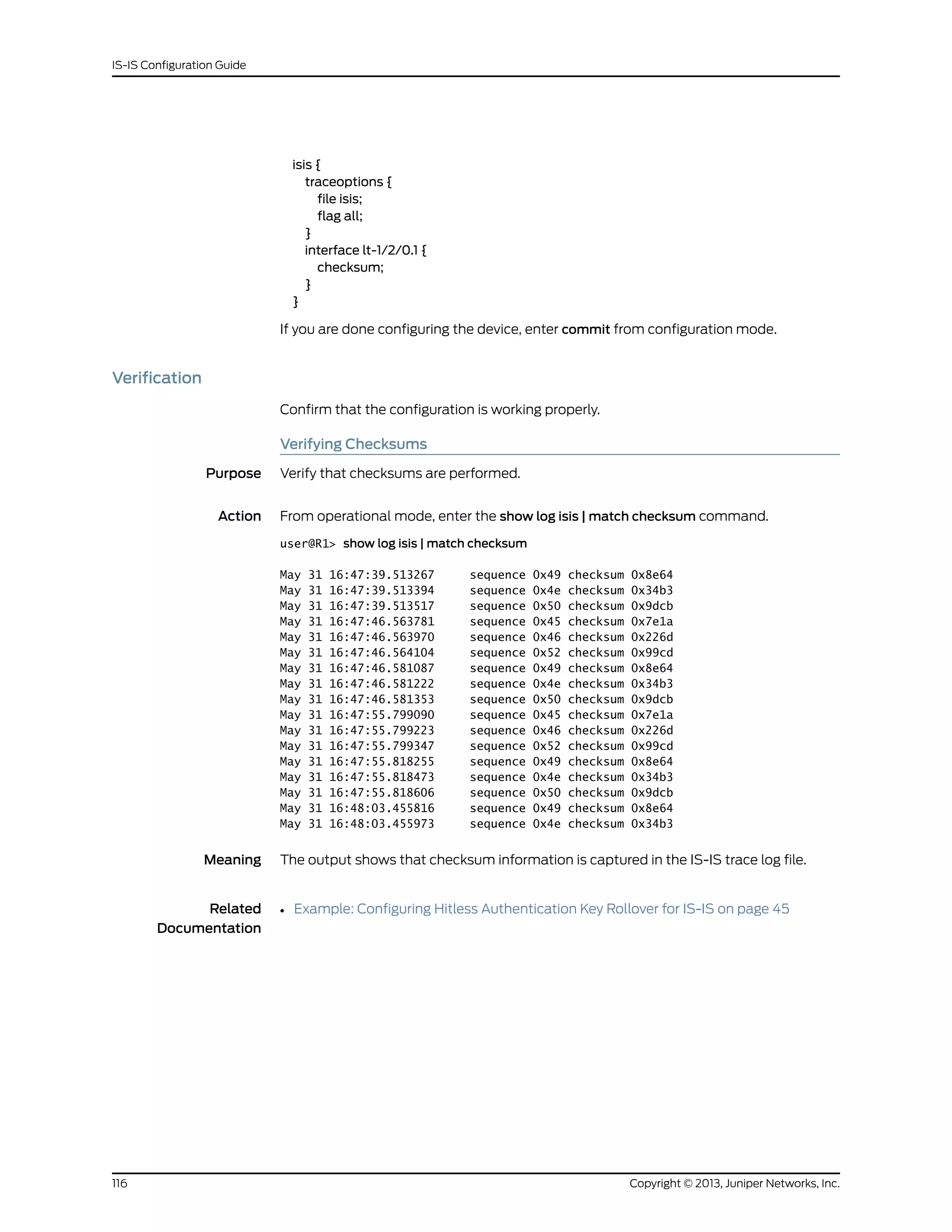
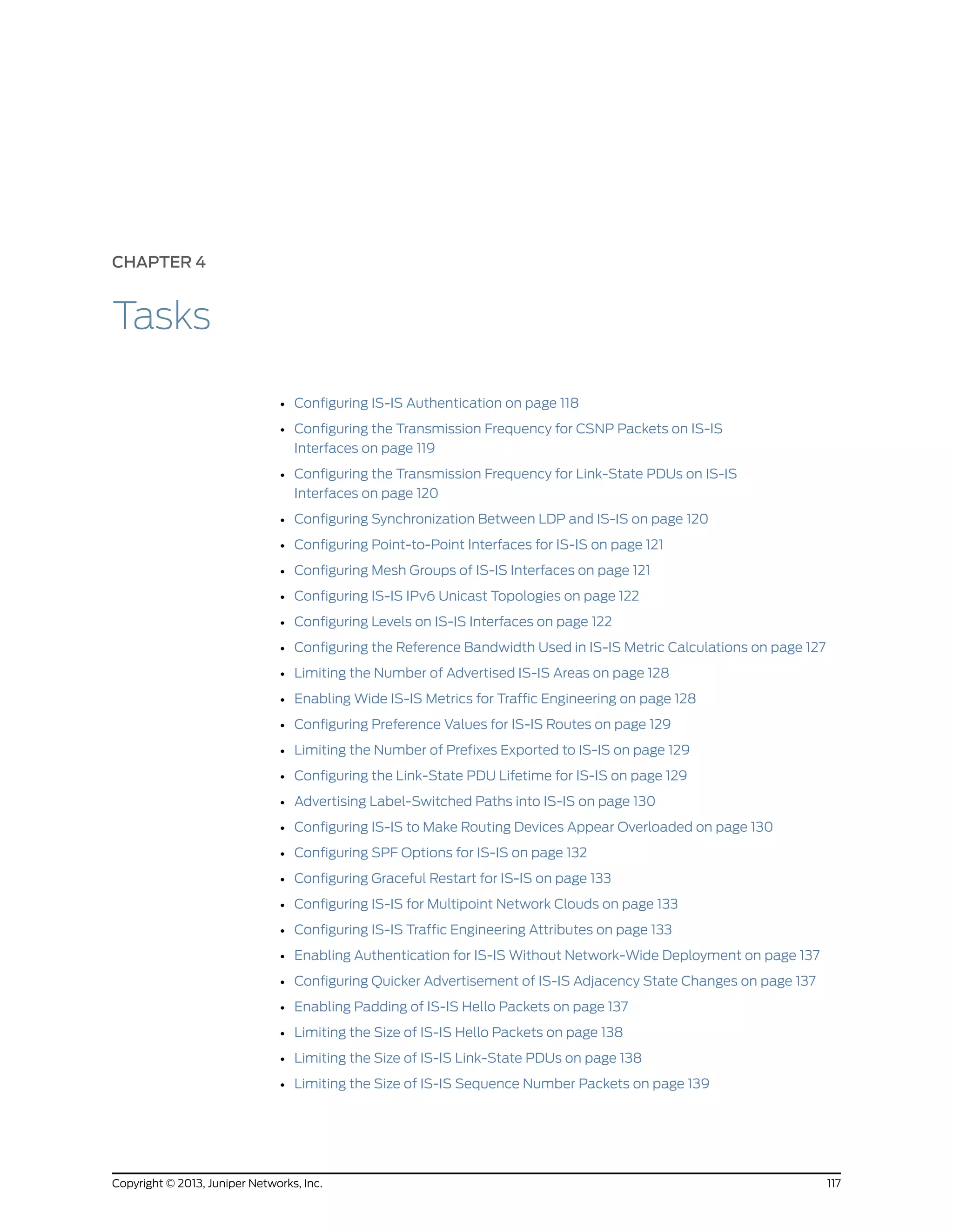
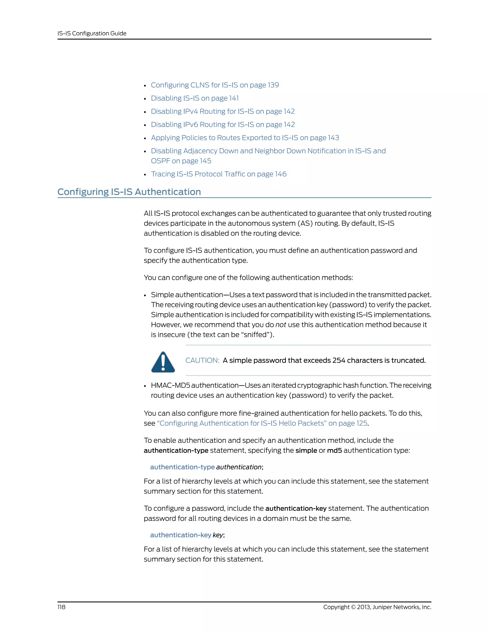
![To configure hitless authentication key rollover, include the authentication-key-chain
(Protocols IS-IS) statement.
The password can contain up to 255 characters. If you include spaces, enclose all
characters in quotation marks (“ ”).
If you are using the Junos OS IS-IS software with another implementation of IS-IS, the
other implementation must be configured to use the same password for the domain, the
area, and all interfaces that are shared with a Junos OS implementation.
Authentication of hello packets, partial sequence number PDU (PSNP), and complete
sequence number PDU (CSNP) may be suppressed to enable interoperability with the
routing software of different vendors. Different vendors handle authentication in various
ways, and suppressing authentication for different PDU types may be the simplest way
to allow compatibility within the same network.
To configure IS-IS to generate authenticated packets, but not to check the authentication
on received packets, include the no-authentication-check statement:
no-authentication-check;
To suppress authentication of IS-IS hello packets, include the no-hello-authentication
statement:
no-hello-authentication;
To suppress authentication of PSNP packets, include the no-psnp-authentication
statement:
no-psnp-authentication;
To suppress authentication of CSNP packets, include the no-csnp-authentication
statement:
no-csnp-authentication;
For a list of hierarchy levels at which you can include these statements, see the statement
summary sections for these statements.
NOTE: The authentication and the no-authentication statements must be
configured at the same hierarchy level. Configuring authentication at the [edit
protocols isis interface interface-name] hierarchy level and configuring
no-authentication at the [edit protocols isis] hierarchy level has no effect.
Configuring the Transmission Frequency for CSNP Packets on IS-IS Interfaces
By default, IS-IS sends complete sequence number (CSN) packets periodically. If the
routing device is the designated router on a LAN, IS-IS sends CSN packets every
10 seconds. If the routing device is on a point-to-point interface, it sends CSN packets
every 5 seconds. You might want to modify the default interval to protect against link-state
PDU (LSP) flooding.
119Copyright © 2013, Juniper Networks, Inc.
Chapter 4: Tasks](https://image.slidesharecdn.com/config-guide-routing-is-is-151104131021-lva1-app6891/75/Juniper-MX-Config-guide-routing-is-is-139-2048.jpg)
![You can configure one Level 1 routing process and one Level 2 routing process on each
interface, and you can configure the two levels differently.
To configure an area, include the level statement:
level level-number {
disable;
hello-authentication-key key;
hello-authentication-key-chain key-chain-name;
hello-authentication-type authentication;
hello-interval seconds;
hold-time seconds;
ipv4-multicast-metric number;
ipv6-multicast-metric number;
ipv6-unicast-metric number;
metric metric;
passive;
priority number;
te-metric metric;
}
For a list of hierarchy levels at which you can include this statement, see the statement
summary section for this statement.
The statements within the level statement allow you to perform the following tasks when
you are configuring the following optional level-specific properties:
• Disabling IS-IS at a Level on IS-IS Interfaces on page 123
• Advertising Interface Addresses Without Running IS-IS on page 124
• Configuring Authentication for IS-IS Hello Packets on page 125
• Configuring the Transmission Frequency for IS-IS Hello Packets on page 125
• Configuring the Delay Before IS-IS Neighbors Mark the Routing Device as
Down on page 125
• Configuring the Metric Value for IS-IS Routes on page 126
• Configuring the IS-IS Metric Value Used for Traffic Engineering on page 127
• Configuring the Designated Router Priority for IS-IS on page 127
Disabling IS-IS at a Level on IS-IS Interfaces
By default, IS-IS is enabled for IS-IS areas on all enabled interfaces on which the ISO
protocol family is enabled (at the [edit interfaces interface unit logical-unit-number]
hierarchy level). To disable IS-IS at any particular level on an interface, include the disable
statement:
disable;
For a list of hierarchy levels at which you can include this statement, see the statement
summary section for this statement.
Enabling IS-IS on an interface (by including the interface statement at the [edit protocols
isis] hierarchy level), disabling it (by including the disable statement), and not actually
123Copyright © 2013, Juniper Networks, Inc.
Chapter 4: Tasks](https://image.slidesharecdn.com/config-guide-routing-is-is-151104131021-lva1-app6891/75/Juniper-MX-Config-guide-routing-is-is-143-2048.jpg)
![having IS-IS run on an interface (by including the passive statement) are mutually
exclusive states.
Example: Disabling IS-IS at a Level
On SONET/SDH interface so-0/0/0, enable IS-IS for Level 1 only. With this configuration,
tracing messages periodically indicate that IS-IS is creating Level 2 link-state PDUs.
However, because IS-IS for Level 2 is disabled, these link-state PDUs are never distributed
to neighboring routers.
protocols {
isis {
traceoptions {
file isis size 1m files 10;
flag spf;
flag lsp;
flag error;
}
interface so-0/0/0 {
level 2 {
disable;
}
}
}
}
Advertising Interface Addresses Without Running IS-IS
By default, IS-IS must be configured on an interface or a level for direct interface addresses
to be advertised into that level. To advertise the direct interface addresses without
actually running IS-IS on that interface or level, include the passive statement:
passive;
NOTE: Configuring IS-IS on a loopback interface automatically renders it as
a passive interface, irrespective of whether the passive statement was used
in the configuration of the interface.
For a list of hierarchy levels at which you can include this statement, see the statement
summary section for this statement.
Enabling IS-IS on an interface (by including the interface statement at the [edit protocols
isis] hierarchy level), disabling it (by including the interface disable statement), and not
actually having IS-IS run on an interface (by including the passive statement) are mutually
exclusive states.
NOTE: If neither passive mode nor the family iso option is configured on the
IS-IS interface, then the routing device treats the interface as not being
operational, and no direct IPv4/IPv6 routes are exported into IS-IS. (You
configure the family iso option at the [edit interfaces interface-name unit
logical-unit-number] hierarchy level.)
Copyright © 2013, Juniper Networks, Inc.124
IS-IS Configuration Guide](https://image.slidesharecdn.com/config-guide-routing-is-is-151104131021-lva1-app6891/75/Juniper-MX-Config-guide-routing-is-is-144-2048.jpg)
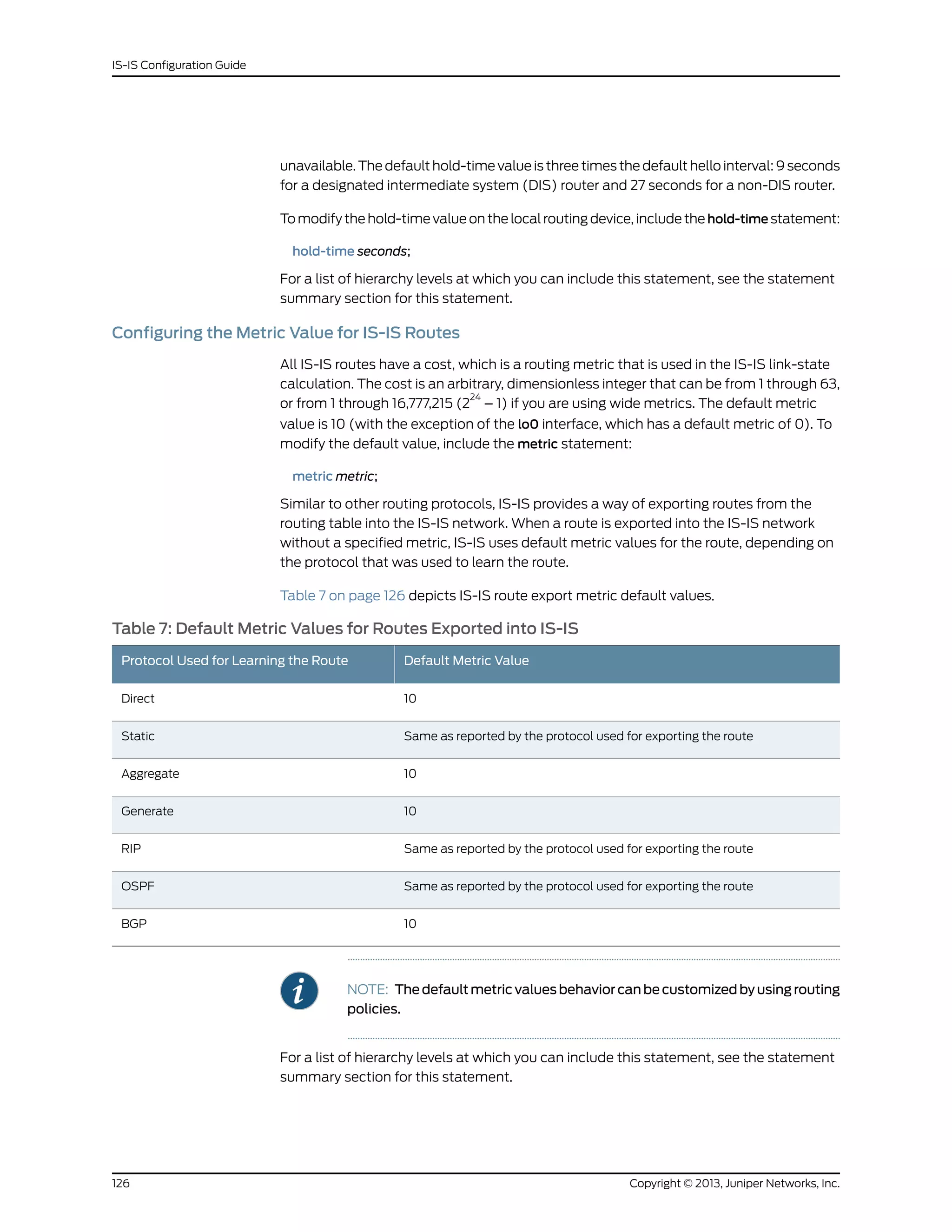

![Configuring Graceful Restart for IS-IS
Graceful restart allows a routing device to restart with minimal effects to the network,
and is enabled globally for all routing protocols at the [edit routing-options] hierarchy
level. When graceful restart for IS-IS is enabled, the restarting routing device is not
removed from the network topology during the restart period. The adjacencies are
reestablished after restart is complete.
You can configure graceful restart parameters specifically for IS-IS. To do this, include
the graceful-restart statement:
graceful-restart {
helper-disable;
restart-duration seconds;
}
For a list of hierarchy levels at which you can include this statement, see the statement
summary section for this statement.
To disable graceful restart for IS-IS, specify the disable statement. Helper mode is enabled
by default. To disable the graceful restart helper capability, specify the helper-disable
statement. To configure a time period for complete restart, specify the restart-duration
statement. You can specify a number between 1 and 300. The default value is 90 seconds.
On LAN interfaces where IS-IS is configured on a transit router that serves as the
designated router (DR), a graceful restart causes:
• The ingress router of the label-switched path (LSP), which passes through the DR, to
break the LSP.
• The ingress router to re-signal the LSP.
Configuring IS-IS for Multipoint Network Clouds
IS-IS does not support multipoint configurations. Therefore, when configuring Frame
Relay or Asynchronous Transfer Mode (ATM) networks, you must configure them as
collections of point-to-point links, not as multipoint clouds.
Configuring IS-IS Traffic Engineering Attributes
You can configure the following IS-IS traffic engineering attributes:
• Configuring IS-IS to Use IGP Shortcuts on page 134
• Configuring IS-IS to Ignore the Metric of RSVP Label-Switched Paths on page 135
• Disabling IS-IS Support for Traffic Engineering on page 135
• Installing IPv4 Routes into the Multicast Routing Table on page 136
• Configuring IS-IS to Use Protocol Preference to Determine the Traffic Engineering
Database Credibility Value on page 136
133Copyright © 2013, Juniper Networks, Inc.
Chapter 4: Tasks](https://image.slidesharecdn.com/config-guide-routing-is-is-151104131021-lva1-app6891/75/Juniper-MX-Config-guide-routing-is-is-153-2048.jpg)
![NOTE: This feature is also supported for OSPFv2. For more information, see
Example: Enabling OSPF Traffic Engineering Support.
To configure IS-IS to use the configured protocol preference for IGP routes to determine
the traffic engineering database credibility value, include the credibility-protocol-preference
statement at the [edit protocols isis traffic-engineering] hierarchy level:
[edit protocols isis]
traffic-engineering {
credibility-protocol-preference;
}
Enabling Authentication for IS-IS Without Network-Wide Deployment
To allow the use of authentication without requiring network-wide deployment, include
the loose-authentication-check statement:
loose-authentication-check;
For a list of hierarchy levels at which you can include this statement, see the statement
summary section for this statement.
Configuring Quicker Advertisement of IS-IS Adjacency State Changes
A hold-down timer delays the advertising of adjacencies by waiting until a time period
has elapsed before labeling adjacencies in the up state. You can disable this hold-down
timer, which labels adjacencies up faster. However, disabling the hold-down timer creates
more frequent link-state PDU updates and SPF computation.
To disable the adjacency hold-down timer, include the no-adjacency-holddown statement:
no-adjacency-holddown;
For a list of hierarchy levels at which you can include this statement, see the statement
summary section for this statement.
Enabling Padding of IS-IS Hello Packets
You can configure padding on hello packets to accommodate asymmetrical maximum
transfer units (MTUs) from different routing devices. This help prevents a premature
adjacency Up state when one routing device’s MTU does not meet the requirements to
establish the adjacency.
As an OSI Layer 2 protocol, IS-IS does not support data fragmentation. Therefore,
maximum packet sizes must be established and supported between two routers. During
adjacency establishment, the IS-IS protocol makes sure that the link supports a packet
size of 1492 bytes by padding outgoing hello packets up to the maximum packet size of
1492 bytes.
To configure padding for hello packets, include the hello-padding statement:
137Copyright © 2013, Juniper Networks, Inc.
Chapter 4: Tasks](https://image.slidesharecdn.com/config-guide-routing-is-is-151104131021-lva1-app6891/75/Juniper-MX-Config-guide-routing-is-is-157-2048.jpg)
![configuring and applying an export policy at the [edit routing-instance instance-name
protocols isis] hierarchy level. ES-IS routes from one routing instance cannot be exported
into a Layer 1 IS-IS area of another routing instance.
To configure an export policy to export BGP routes into IS-IS, include the policy-statement
statement:
policy-statement policy-name {
from {
protocol bgp;
family iso;
}
then {
accept;
}
}
To apply an export policy, include the export statement at the [editprotocolsisis] hierarchy
level:
export policy-name;
For a list of hierarchy levels at which you can include this statement, see the statement
summary section for these statements.
For more information on policy configuration, see the Routing Policy Configuration Guide.
You can also export routes from protocols other than BGP into IS-IS. ES-IS routes are
exported to IS-IS by default. You can export ES-IS routes into IS-IS by configuring a
routing policy.
Example: Configuring CLNS for IS-IS
Configure a routing policy to accept CLNS routes:
policy-options {
policy-statement dist-bgp {
from {
protocol bgp;
family iso;
}
then accept;
}
policy-statement dist-static {
from {
protocol static;
family iso;
}
then accept;
}
}
Configure CLNS for IS-IS:
protocols {
isis {
Copyright © 2013, Juniper Networks, Inc.140
IS-IS Configuration Guide](https://image.slidesharecdn.com/config-guide-routing-is-is-151104131021-lva1-app6891/75/Juniper-MX-Config-guide-routing-is-is-160-2048.jpg)
![traceoptions {
file isis size 5m world-readable;
flag error;
}
export dist-static;
no-ipv6-routing;
no-ipv4-routing;
clns-routing;
interface fe-0/0/1.0;
interface t1-0/2/1.0;
interface fxp0.0 {
disable;
}
interface lo0.0;
}
}
Configure a routing instance that supports CLNS routes:
routing-instances {
aaaa {
instance-type vrf;
interface lo0.1;
interface t1-3/0/0.0;
interface fe-5/0/1.0;
route-distinguisher 10.245.245.1:1;
vrf-target target:11111:1;
protocols {
isis {
export dist-bgp;
no-ipv4-routing;
no-ipv6-routing;
clns-routing;
interface all;
}
}
}
}
Disabling IS-IS
To disable IS-IS on the routing device without removing the IS-IS configuration statements
from the configuration, include the disable statement:
isis {
disable;
}
For a list of hierarchy levels at which you can include this statement, see the statement
summary section for this statement.
To reenable IS-IS, remove the disable statement from the configuration:
[edit protocols]
user@host# delete isis disable
[edit protocols]
141Copyright © 2013, Juniper Networks, Inc.
Chapter 4: Tasks](https://image.slidesharecdn.com/config-guide-routing-is-is-151104131021-lva1-app6891/75/Juniper-MX-Config-guide-routing-is-is-161-2048.jpg)
![user@host# show
isis;
Disabling IPv4 Routing for IS-IS
You can disable IP version 4 (IPv4) routing for IS-IS. Disabling IPv4 routing results in the
following:
• The routing device does not advertise the NLPID for IPv4 in the Junos OS link-state
PDU fragment zero.
• The routing device does not advertise any IPv4 prefixes in Junos OS link-state PDUs.
• The routing device does not advertise the NLPID for IPv4 in Junos OS hello packets.
• The routing device does not advertise any IPv4 addresses in Junos OS hello packets.
• The routing device does not calculate any IPv4 routes.
To disable IPv4 routing on the routing device, include the no-ipv4-routing statement:
isis {
no-ipv4-routing;
}
For a list of hierarchy levels at which you can include this statement, see the statement
summary section for this statement.
To reenable IS-IS, remove the no-ipv4-routing statement from the configuration:
[edit protocols]
user@host# delete isis no-ipv4-routing
NOTE: Note: Even when no-ipv4-routing is configured, an IS-IS traceoptions
log can list rejected IPv4 addresses. When a configuration is committed, IS-IS
schedules a scan of the routing table to determine whether any routes need
to be exported into the IS-IS link state database. The implicit default export
policy action is to reject everything. IPv4 addresses from the routing table
are examined for export, rejected by the default policy, and the rejections are
logged.
Disabling IPv6 Routing for IS-IS
You can disable IP version 6 (IPv6) routing for IS-IS. Disabling IPv6 routing results in the
following:
• Routing device does not advertise the NLPID for IPv6 in Junos OS 0th link-state PDU
fragment.
• Routing device does not advertise any IPv6 prefixes in Junos OS link-state PDUs.
• Routing device does not advertise the NLPID for IPv6 in Junos OS hello packets.
Copyright © 2013, Juniper Networks, Inc.142
IS-IS Configuration Guide](https://image.slidesharecdn.com/config-guide-routing-is-is-151104131021-lva1-app6891/75/Juniper-MX-Config-guide-routing-is-is-162-2048.jpg)
![• Routing device does not advertise any IPv6 addresses in Junos OS hello packets.
• Routing device does not calculate any IPv6 routes.
To disable IPv6 routing on the routing device, include the no-ipv6-routing statement:
isis {
no-ipv6-routing;
}
For a list of hierarchy levels at which you can include this statement, see the statement
summary section for this statement.
To re-enable IS-IS, remove the disable statement from the configuration:
[edit protocols]
user@host# delete isis no-ipv6-routing
Applying Policies to Routes Exported to IS-IS
All routing protocols store the routes that they learn in the routing table. The routing table
uses this collected route information to determine the active routes to destinations. The
routing table then installs the active routes into its forwarding table and exports them
into the routing protocols. It is these exported routes that the protocols advertise.
For each protocol, you control which routes the protocol stores in the routing table and
which routes the routing table exports into the protocol from the routing table by defining
a routing policy for that protocol. For information about defining routing policy, see the
Routing Policy Configuration Guide.
To apply routing policies that affect how the routing protocol process (rpd) exports
routes into IS-IS, include the export statement:
export [ policy-names ];
For a list of hierarchy levels at which you can include this statement, see the statement
summary section for this statement.
NOTE: For IS-IS, you cannot apply routing policies that affect how routes are
imported into the routing table; doing so with a link-state protocol can easily
lead to an inconsistent topology database.
Examples: Configuring IS-IS Routing Policy
Define a policy that allows only host routes from USC (128.125.0.0/16), and apply the
policy to routes exported from the routing table into IS-IS:
policy-options {
policy-statement usc-hosts-only {
term first {
from {
route-filter 128.125.0.0/16 upto /31;
}
143Copyright © 2013, Juniper Networks, Inc.
Chapter 4: Tasks](https://image.slidesharecdn.com/config-guide-routing-is-is-151104131021-lva1-app6891/75/Juniper-MX-Config-guide-routing-is-is-163-2048.jpg)
![then reject;
}
then accept;
}
}
protocols {
isis {
export usc-hosts-only;
}
}
Define a policy that takes BGP routes from the Edu community and places them into
IS-IS with a metric of 14. Apply the policy to routes exported from the routing table into
IS-IS:
protocols {
isis {
export edu-to-isis;
}
}
policy-options {
community Edu members 666:5;
policy-statement edu-to-isis {
from {
protocol bgp;
community Edu;
}
to protocol isis;
then metric 14;
}
}
Define a policy that rejects all IS-IS Level 1 routes so that none are exported into IS-IS:
policy-options {
policy-statement level1 {
term first {
from level 1;
then reject;
}
then accept;
}
}
protocols {
isis {
export level1;
interface fxp0;
}
}
Define a routing policy to export IS-IS Level 1 internal-only routes into Level 2:
[edit]
protocols {
isis {
export L1-L2;
}
Copyright © 2013, Juniper Networks, Inc.144
IS-IS Configuration Guide](https://image.slidesharecdn.com/config-guide-routing-is-is-151104131021-lva1-app6891/75/Juniper-MX-Config-guide-routing-is-is-164-2048.jpg)
![}
policy-statement L1-L2 {
term one {
from {
level 1;
external;
}
then reject;
}
term two {
from level 1;
to level 2;
then accept;
}
}
Define a routing policy to export IS-IS Level 2 routes into Level 1:
[edit]
protocols {
isis {
export L2-L1;
}
}
policy-statement L2-L1 {
term one {
from level 2;
to level 1;
then accept;
}
}
Disabling Adjacency Down and Neighbor Down Notification in IS-IS and OSPF
Whenever IS-IS is deactivated, the IS-IS adjacencies are brought down. IS-IS signals to
RSVP to bring down any RSVP neighbors associated with the IS-IS adjacencies, and this
further causes the associated LSPs signaled by RSVP to go down as well.
A similar process occurs whenever OSPF is deactivated. The OSPF neighbors are brought
down. OSPF signals to RSVP to bring down any of the RSVP neighbors associated with
the OSPF neighbors, and this further causes the associated LSPs signaled by RSVP to
go down as well.
If you need to migrate from IS-IS to OSPF or from OSPF to IS-IS, the IGP notification to
RSVP for an adjacency or neighbor down event needs to be ignored. Using the
no-adjacency-down-notification or no-neighbor-down-notification statements, you can
disable IS-IS adjacency down notification or OSPF neighbor down notification,
respectively, until the migration is complete. The network administrator is responsible
for configuring the statements before the migration, and then removing them from the
configuration afterward, so that IGP notification can function normally.
To disable adjacency down notification in IS-IS, include the
no-adjacency-down-notification statement:
no-adjacency-down-notification;
145Copyright © 2013, Juniper Networks, Inc.
Chapter 4: Tasks](https://image.slidesharecdn.com/config-guide-routing-is-is-151104131021-lva1-app6891/75/Juniper-MX-Config-guide-routing-is-is-165-2048.jpg)
![You can include this statement at the following hierarchy levels:
• [edit protocols isis interface interface-name]
• [edit logical-systems logical-system-name protocols isis interface interface-name]
To disable neighbor down notification in OSPF, include the no-neighbor-down-notification
statement:
no-neighbor-down-notification;
You can include this statement at the following hierarchy levels:
• [edit protocols ospf area area-id interface interface-name]
• [edit logical-systems logical-system-name protocols ospf area area-id interface
interface-name]
Tracing IS-IS Protocol Traffic
You can trace various types of IS-IS protocol traffic to help debug IS-IS protocol issues.
To trace IS-IS protocol traffic, include the traceoptions statement at the [edit protocols
isis] hierarchy level:
traceoptions {
file filename <files number> <size size> <world-readable | no-world-readable>;
flag flag <flag-modifier> <disable>;
}
You can specify the following IS-IS protocol-specific trace options using the flag
statement:
• csn—Complete sequence number PDU (CSNP) packets
• error—Errored packets
• graceful-restart—Graceful restart operations
• hello—Hello packets
• ldp-synchronization—Synchronization between IS-IS and LDP
• lsp—Link-state PDU packets
• lsp-generation—Link-state PDU generation packets
• nsr-synchronization—NSR synchronization events
• packets—All IS-IS protocol packets
• psn—Partial sequence number PDU (PSNP) packets
• spf—Shortest-path-first (SPF) calculations
You can optionally specify one or more of the following flag modifiers:
• detail—Detailed trace information
• receive—Packets being received
Copyright © 2013, Juniper Networks, Inc.146
IS-IS Configuration Guide](https://image.slidesharecdn.com/config-guide-routing-is-is-151104131021-lva1-app6891/75/Juniper-MX-Config-guide-routing-is-is-166-2048.jpg)
![• send—Packets being transmitted
NOTE: Use the flag modifier detail with caution as this may cause the CPU
to become very busy.
Global tracing options are inherited from the configuration set by the traceoptions
statement at the [edit routing-options] hierarchy level. You can override the following
global trace options for the IS-IS protocol using the traceoptions flag statement included
at the [edit protocols isis] hierarchy level:
• all—All tracing operations
• general—All normal operations and routing table changes (a combination of the normal
and route trace operations)
• normal—Normal events
• policy—Policy processing
• route—Routing information
• state—State transitions
• task—Routing protocol task processing
• timer—Routing protocol timer processing
NOTE: Use the trace flag all with caution as this may cause the CPU to
become very busy.
Examples: Tracing IS-IS Protocol Traffic
A common configuration traces SPF calculations, LSP calculations, normal protocol
operations, and errors in protocol operation:
[edit]
protocols {
isis {
traceoptions {
file isis-log size 1m files 10;
flag spf;
flag lsp;
flag error;
flag normal;
}
}
}
Trace only unusual or abnormal operations to the file routing-log, and trace detailed
information about all IS-IS packets to the file isis-log:
[edit]
147Copyright © 2013, Juniper Networks, Inc.
Chapter 4: Tasks](https://image.slidesharecdn.com/config-guide-routing-is-is-151104131021-lva1-app6891/75/Juniper-MX-Config-guide-routing-is-is-167-2048.jpg)
![routing-options {
traceoptions {
file routing-log;
}
}
protocols {
isis {
traceoptions {
file isis-log size 10k files 5;
flag csn detail;
flag hello detail;
flag lsp detail;
flag psn detail;
}
}
}
Perform detailed tracing of mesh-group flooding:
[edit]
protocols {
isis {
traceoptions {
file isis-log;
flag lsp detail;
}
}
}
IS-IS LSP packets that contain errors are discarded by default. To log these errors, specify
the error tracing operation:
[edit]
protocols {
isis {
traceoptions {
file isis-log;
flag error;
}
}
}
Related
Documentation
• traceoptions on page 225
• For more information about tracing and global tracing options, see Example: Tracing
Global Routing Protocol Operations.
Copyright © 2013, Juniper Networks, Inc.148
IS-IS Configuration Guide](https://image.slidesharecdn.com/config-guide-routing-is-is-151104131021-lva1-app6891/75/Juniper-MX-Config-guide-routing-is-is-168-2048.jpg)
![CHAPTER 5
Configuration Statements
• [edit protocols isis] Hierarchy Level on page 149
[edit protocols isis] Hierarchy Level
The following statement hierarchy can also be included at the [edit logical-systems
logical-system-name] hierarchy level.
protocols {
isis {
disable;
clns-routing;
context-identifier ip-address</prefix> {
level (1 | 2) <disable>;
}
export [ policy-names ];
graceful-restart {
disable;
helper-disable;
restart-duration seconds;
}
ignore-attached-bit;
interface interface-name {
... the interface subhierarchy appears after the main [edit protocols isis] hierarchy ...
}
label-switched-path name level level metric metric;
level (1 | 2) {
disable;
authentication-key key;
authentication-type authentication;
external-preference preference;
no-csnp-authentication;
no-hello-authentication;
no-psnp-authentication;
preference preference;
prefix-export-limit number;
wide-metrics-only;
}
loose-authentication-check;
lsp-lifetime seconds;
max-areas number;
no-adjacency-holddown;
149Copyright © 2013, Juniper Networks, Inc.](https://image.slidesharecdn.com/config-guide-routing-is-is-151104131021-lva1-app6891/75/Juniper-MX-Config-guide-routing-is-is-169-2048.jpg)
![multiplier number;
no-adaptation;
transmit-interval {
minimum-interval milliseconds;
threshold milliseconds;
}
version (1 | automatic);
}
checksum;
csnp-interval (seconds | disable);
hello-padding (adaptive | loose | strict);
ldp-synchronization {
disable;
hold-time seconds;
}
level (1 | 2) {
disable;
hello-authentication-key key;
hello-authentication-type authentication;
hello-interval seconds;
hold-time seconds;
ipv4-multicast-metric number;
ipv6-multicast-metric number;
ipv6-unicast-metric number;
metric metric;
passive;
priority number;
te-metric metric;
}
link-protection;
lsp-interval milliseconds;
mesh-group (value | blocked);
no-adjacency-down-notification;
no-eligible-backup;
no-ipv4-multicast;
no-ipv6-multicast;
no-ipv6-unicast;
no-unicast-topology;
node-link-protection;
passive;
point-to-point;
}
}
}
Related
Documentation
Notational Conventions Used in Junos OS Configuration Hierarchies•
• [edit protocols] Hierarchy Level
151Copyright © 2013, Juniper Networks, Inc.
Chapter 5: Configuration Statements](https://image.slidesharecdn.com/config-guide-routing-is-is-151104131021-lva1-app6891/75/Juniper-MX-Config-guide-routing-is-is-171-2048.jpg)
![authentication-key (Protocols IS-IS)
Syntax authentication-key key;
Hierarchy Level [edit logical-systems logical-system-name protocols isis level level-number],
[editlogical-systemslogical-system-namerouting-instancesrouting-instance-nameprotocols
isis level level-number],
[edit protocols isis level level-number],
[edit routing-instances routing-instance-name protocols isis level level-number]
Release Information Statement introduced before Junos OS Release 7.4.
Statement introduced in Junos OS Release 9.0 for EX Series switches.
Statement introduced in Junos OS Release 12.1 for the QFX Series.
Description Authentication key (password). Neighboring routing devices use the password to verify
the authenticity of packets sent from this interface. For the key to work, you also must
include the authentication-type statement.
All routing devices must use the same password. If you are using the Junos OS IS-IS
software with another implementation of IS-IS, the other implementation must be
configured to use the same password for the domain, the area, and all interfaces adjacent
to the Juniper Networks routing device.
Default If you do not include this statement and the authentication-type statement, IS-IS
authentication is disabled.
Options key—Authentication password. The password can be up to 1024 characters long.
Characters can include any ASCII strings. If you include spaces, enclose all characters
in quotation marks (“ ”).
CAUTION: A simple password for authentication is truncated if it exceeds
254 characters.
Required Privilege
Level
routing—To view this statement in the configuration.
routing-control—To add this statement to the configuration.
Related
Documentation
• Configuring IS-IS Authentication on page 118
Copyright © 2013, Juniper Networks, Inc.152
IS-IS Configuration Guide](https://image.slidesharecdn.com/config-guide-routing-is-is-151104131021-lva1-app6891/75/Juniper-MX-Config-guide-routing-is-is-172-2048.jpg)
![authentication-key-chain (Protocols IS-IS)
Syntax authentication-key-chain key-chain-name;
Hierarchy Level [edit logical-systems name protocols isis level level-number],
[editlogical-systemsnamerouting-instancesinstance-nameprotocolsisislevellevel-number],
[edit protocols isis level level-number],
[edit routing-instances instance-name protocols isis level level-number]
Release Information Statement introduced in Junos OS Release 11.2.
Statement introduced in Junos OS Release 12.1 for the QFX Series.
Description Apply and enable an authentication keychain to the routing device.
Options key-chain—Authentication keychain name. It can be up to 126 characters. Characters can
include any ASCII strings. If you include spaces, enclose all characters in quotation
marks (“ ”).
Required Privilege
Level
routing—To view this statement in the configuration.
routing-control—To add this statement to the configuration.
Related
Documentation
• Example: Configuring Route Authentication for BGP
• Configuring the Authentication Key Update Mechanism for BGP and LDP Routing
Protocols
• Example: Configuring BFD Authentication for Static Routes
• Overview of Hitless Authentication Key Rollover for IS-IS on page 45
• Example: Configuring Hitless Authentication Key Rollover for IS-IS on page 46
153Copyright © 2013, Juniper Networks, Inc.
Chapter 5: Configuration Statements](https://image.slidesharecdn.com/config-guide-routing-is-is-151104131021-lva1-app6891/75/Juniper-MX-Config-guide-routing-is-is-173-2048.jpg)
![authentication-type (Protocols IS-IS)
Syntax authentication-type authentication;
Hierarchy Level [edit logical-systems logical-system-name protocols isis level level-number],
[editlogical-systemslogical-system-namerouting-instancesrouting-instance-nameprotocols
isis level level-number],
[edit protocols isis level level-number],
[edit routing-instances routing-instance-name protocols isis level level-number]
Release Information Statement introduced before Junos OS Release 7.4.
Statement introduced in Junos OS Release 9.0 for EX Series switches.
Statement introduced in Junos OS Release 12.1 for the QFX Series.
Description Enable authentication and specify the authentication scheme for IS-IS. If you enable
authentication, you must specify a password by including the authentication-key
statement.
Default If you do not include this statement and the authentication-key statement, IS-IS
authentication is disabled.
Options authentication—Authentication scheme:
• md5—Use HMAC authentication in combination with MD5. HMAC-MD5 authentication
is defined in RFC 2104, HMAC: Keyed-Hashing for Message Authentication.
• simple—Use a simple password for authentication. The password is included in the
transmitted packet, making this method of authentication relatively insecure. We
recommend that you not use this authentication method.
Required Privilege
Level
routing—To view this statement in the configuration.
routing-control—To add this statement to the configuration.
Related
Documentation
• authentication-key on page 152
• no-authentication-check on page 199
• Configuring IS-IS Authentication on page 118
Copyright © 2013, Juniper Networks, Inc.154
IS-IS Configuration Guide](https://image.slidesharecdn.com/config-guide-routing-is-is-151104131021-lva1-app6891/75/Juniper-MX-Config-guide-routing-is-is-174-2048.jpg)
![bfd-liveness-detection (Protocols IS-IS)
Syntax bfd-liveness-detection {
authentication {
algorithm algorithm-name;
key-chain key-chain-name;
loose-check;
}
detection-time {
threshold milliseconds;
}
minimum-interval milliseconds;
minimum-receive-interval milliseconds;
multiplier number;
no-adaptation;
transmit-interval {
minimum-interval milliseconds;
threshold milliseconds;
}
version (1 | automatic);
}
Hierarchy Level [edit logical-systems logical-system-name protocols isis interface interface-name],
[editlogical-systemslogical-system-namerouting-instancesrouting-instance-nameprotocols
isis interface interface-name],
[edit protocols isis interface interface-name],
[edit routing-instances routing-instance-name protocols isis interface interface-name]
Release Information Statement introduced before Junos OS Release 7.4.
Statement introduced in Junos OS Release 9.0 for EX Series switches.
detection-time threshold and transmit-interval threshold options added in Junos OS
Release 8.2.
Support for logical systems introduced in Junos OS Release 8.3.
no-adaptation statement introduced in Junos OS Release 9.0.
authenticationalgorithm, authenticationkey-chain, and authenticationloose-check options
introduced in Junos OS Release 9.6.
Statement introduced in Junos OS Release 12.1 for the QFX Series.
Description Configure bidirectional failure detection timers and authentication.
Options authentication algorithm algorithm-name —Configure the algorithm used to authenticate
the specified BFD session: simple-password, keyed-md5, keyed-sha-1,
meticulous-keyed-md5, meticulous-keyed-sha-1.
authentication key-chain key-chain-name—Associate a security key with the specified
BFD session using the name of the security keychain. The name you specify must
match one of the keychains configured in the authentication-key-chains key-chain
statement at the [edit security] hierarchy level.
authentication loose-check—(Optional) Configure loose authentication checking on the
BFD session. Use only for transitional periods when authentication may not be
configured at both ends of the BFD session.
155Copyright © 2013, Juniper Networks, Inc.
Chapter 5: Configuration Statements](https://image.slidesharecdn.com/config-guide-routing-is-is-151104131021-lva1-app6891/75/Juniper-MX-Config-guide-routing-is-is-175-2048.jpg)
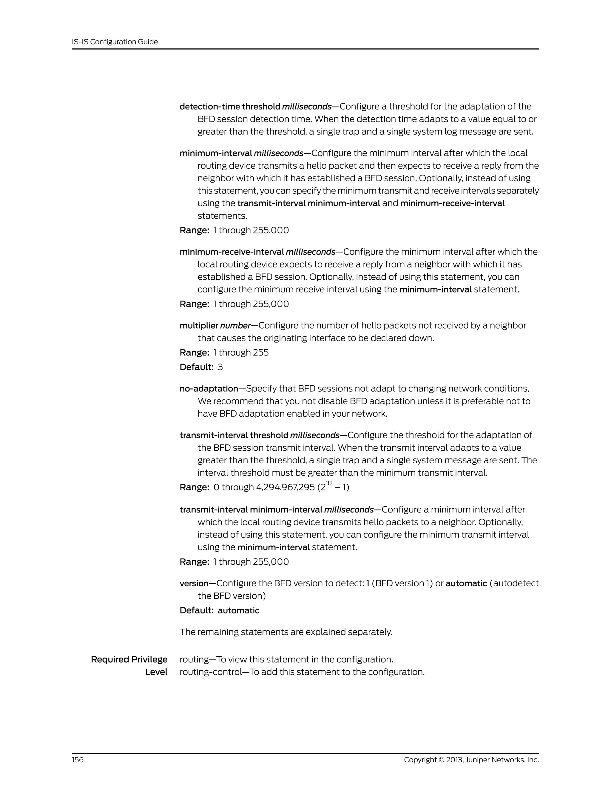
![Related
Documentation
• Example: Configuring BFD for IS-IS on page 59
• Configuring BFD Authentication for IS-IS on page 69
checksum
Syntax checksum;
Hierarchy Level [edit logical-systems logical-system-name protocols isis interface interface-name],
[editlogical-systemslogical-system-namerouting-instancesrouting-instance-nameprotocols
isis interface interface-name],
[edit protocols isis interface interface-name],
[edit routing-instances routing-instance-name protocols isis interface interface-name]
Release Information Statement introduced before Junos OS Release 7.4.
Statement introduced in Junos OS Release 9.0 for EX Series switches.
Statement introduced in Junos OS Release 12.1 for the QFX Series.
Description Enable checksums for packets on this interface.
Junos OS supports IS-IS checksums as documented in RFC 3358, Optional Checksums
in Intermediate System to Intermediate System (ISIS).
The checksum cannot be enabled with MD5 hello authentication on the same interface.
Required Privilege
Level
routing—To view this statement in the configuration.
routing-control—To add this statement to the configuration.
Related
Documentation
• IS-IS Configuration Guide
context-identifier
Syntax context-identifier identifier
Hierarchy Level [edit logical-systems logical-system-name protocols isis],
[edit protocols isis]
Release Information Statement introduced in Junos OS Release 10.4.
Description Configure IS-IS context identifier information.
Options identifier—IPv4 address that defines a protection pair. The context identifier is manually
configured on both primary and protector PEs.
Required Privilege
Level
routing—To view this statement in the configuration.
routing-control—To add this statement to the configuration.
Related
Documentation
• show isis context-identifier on page 258
157Copyright © 2013, Juniper Networks, Inc.
Chapter 5: Configuration Statements](https://image.slidesharecdn.com/config-guide-routing-is-is-151104131021-lva1-app6891/75/Juniper-MX-Config-guide-routing-is-is-177-2048.jpg)
![clns-routing
Syntax clns-routing;
Hierarchy Level [edit protocols isis],
[edit routing-instances routing-instance-name protocols isis]
Release Information Statement introduced before Junos OS Release 7.4.
Description Enable IS-IS to exchange CLNS routes.
NOTE: CLNS is supported on J Series Services Routers and MX Series routers
only.
Required Privilege
Level
routing—To view this statement in the configuration.
routing-control—To add this statement to the configuration.
Related
Documentation
• Configuring CLNS for IS-IS on page 139
Copyright © 2013, Juniper Networks, Inc.158
IS-IS Configuration Guide](https://image.slidesharecdn.com/config-guide-routing-is-is-151104131021-lva1-app6891/75/Juniper-MX-Config-guide-routing-is-is-178-2048.jpg)
![csnp-interval
Syntax csnp-interval (seconds | disable);
Hierarchy Level [edit logical-systems logical-system-name protocols isis interface interface-name],
[editlogical-systemslogical-system-namerouting-instancesrouting-instance-nameprotocols
isis interface interface-name],
[edit protocols isis interface interface-name],
[edit routing-instances routing-instance-name protocols isis interface interface-name]
Release Information Statement introduced before Junos OS Release 7.4.
Statement introduced in Junos OS Release 9.0 for EX Series switches.
Statement introduced in Junos OS Release 12.1 for the QFX Series.
Description Configure the interval between complete sequence number (CSN) packets on a LAN
interface.
You might want to modify the default interval to protect against link-state PDU (LSP)
flooding.
To modify the CSNP interval, include the csnp-interval statement.
To configure the interface not to send any CSN packets, specify the disable option.
Default By default, IS-IS sends complete sequence number (CSN) packets periodically. If the
routing device is the designated router on a LAN, IS-IS sends CSN packets every
10 seconds. If the routing device is on a point-to-point interface, it sends CSN packets
every 5 seconds.
Options disable—Do not send CSN packets on this interface.
seconds—Number of seconds between the sending of CSN packets.
Range: 1 through 65,535 seconds
Default: 10 seconds
Required Privilege
Level
routing—To view this statement in the configuration.
routing-control—To add this statement to the configuration.
Related
Documentation
• Configuring the Transmission Frequency for CSNP Packets on IS-IS Interfaces on
page 119
159Copyright © 2013, Juniper Networks, Inc.
Chapter 5: Configuration Statements](https://image.slidesharecdn.com/config-guide-routing-is-is-151104131021-lva1-app6891/75/Juniper-MX-Config-guide-routing-is-is-179-2048.jpg)
![disable (Protocols IS-IS)
Syntax disable;
Hierarchy Level [edit logical-systems logical-system-name protocols isis],
[edit logical-systems logical-system-name protocols isis interface interface-name],
[edit logical-systems logical-system-name protocols isis interface interface-name level
level-number],
[edit logical-systems logical-system-name protocols isis traffic-engineering],
[editlogical-systemslogical-system-namerouting-instancesrouting-instance-nameprotocols
isis],
[editlogical-systemslogical-system-namerouting-instancesrouting-instance-nameprotocols
isis interface interface-name],
[edit logical-systems logical-system-name routing-instances routing-instance-name
protocols isis interface interface-name level level-number],
[editlogical-systemslogical-system-namerouting-instancesrouting-instance-nameprotocols
isis traffic-engineering],
[edit protocols isis],
[edit protocols isis interface interface-name],
[edit protocols isis interface interface-name level level-number],
[edit protocols isis traffic-engineering],
[edit routing-instances routing-instance-name protocols isis],
[edit routing-instances routing-instance-name protocols isis interface interface-name],
[edit routing-instances routing-instance-name protocols isis interface interface-name level
level-number],
[edit routing-instances routing-instance-name protocols isis traffic-engineering]
Release Information Statement introduced before Junos OS Release 7.4.
Statement introduced in Junos OS Release 9.0 for EX Series switches.
Statement introduced in Junos OS Release 12.1 for the QFX Series.
Description Disable IS-IS on the routing device, on an interface, or on a level.
At the [edit protocols isis traffic-engineering] hierarchy level, disable IS-IS support for
traffic engineering.
Enabling IS-IS on an interface (by including the interface statement at the [edit protocols
isis] or the [edit routing-instances routing-instance-name protocols isis] hierarchy level),
disabling it (by including the disable statement), and not actually having IS-IS run on an
interface (by including the passive statement) are mutually exclusive states.
Default IS-IS is enabled for Level 1 and Level 2 routers on all interfaces on which family iso is
enabled.
IS-IS support for traffic engineering is enabled.
Required Privilege
Level
routing—To view this statement in the configuration.
routing-control—To add this statement to the configuration.
Related
Documentation
Example: Configuring Multi-Level IS-IS on page 20•
• IS-IS Overview on page 3
Copyright © 2013, Juniper Networks, Inc.160
IS-IS Configuration Guide](https://image.slidesharecdn.com/config-guide-routing-is-is-151104131021-lva1-app6891/75/Juniper-MX-Config-guide-routing-is-is-180-2048.jpg)
![• Disabling IS-IS on page 141
disable (LDP Synchronization for IS-IS)
Syntax disable;
Hierarchy Level [edit logical-systems logical-system-name protocols isis interface interface-name
ldp-synchronization],
[editlogical-systemslogical-system-namerouting-instancesrouting-instance-nameprotocols
isis interface interface-name ldp-synchronization],
[edit protocols isis interface interface-name ldp-synchronization],
[edit routing-instances routing-instance-name protocols isis interface interface-name
ldp-synchronization]
Release Information Statement introduced in Junos OS Release 7.5.
Description Disable LDP synchronization for IS-IS.
Required Privilege
Level
routing—To view this statement in the configuration.
routing-control—To add this statement to the configuration.
Related
Documentation
• Configuring Synchronization Between LDP and IS-IS on page 120
161Copyright © 2013, Juniper Networks, Inc.
Chapter 5: Configuration Statements](https://image.slidesharecdn.com/config-guide-routing-is-is-151104131021-lva1-app6891/75/Juniper-MX-Config-guide-routing-is-is-181-2048.jpg)
![export (Protocols IS-IS)
Syntax export [ policy-names ];
Hierarchy Level [edit logical-systems logical-system-name protocols isis],
[editlogical-systemslogical-system-namerouting-instancesrouting-instance-nameprotocols
isis],
[edit protocols isis],
[edit routing-instances routing-instance-name protocols isis]
Release Information Statement introduced before Junos OS Release 7.4.
Statement introduced in Junos OS Release 9.0 for EX Series switches.
Statement introduced in Junos OS Release 12.1 for the QFX Series.
Description Apply one or more policies to routes being exported from the routing table into IS-IS.
All routing protocols store the routes that they learn in the routing table. The routing table
uses this collected route information to determine the active routes to destinations. The
routing table then installs the active routes into its forwarding table and exports them
into the routing protocols. It is these exported routes that the protocols advertise.
For each protocol, you control which routes the protocol stores in the routing table and
which routes the routing table exports into the protocol from the routing table by defining
a routing policy for that protocol.
NOTE: For IS-IS, you cannot apply routing policies that affect how routes are
imported into the routing table; doing so with a link-state protocol can easily
lead to an inconsistent topology database.
Options policy-names—Name of one or more policies.
Required Privilege
Level
routing—To view this statement in the configuration.
routing-control—To add this statement to the configuration.
Related
Documentation
• Example: Redistributing OSPF Routes into IS-IS on page 51
• Example: Configuring an IS-IS Default Route Policy on Logical Systems on page 106
Copyright © 2013, Juniper Networks, Inc.162
IS-IS Configuration Guide](https://image.slidesharecdn.com/config-guide-routing-is-is-151104131021-lva1-app6891/75/Juniper-MX-Config-guide-routing-is-is-182-2048.jpg)
![external-preference (Protocols IS-IS)
Syntax external-preference preference;
Hierarchy Level [edit logical-systems logical-system-name protocols isis level level-number],
[editlogical-systemslogical-system-namerouting-instancesrouting-instance-nameprotocols
isis level level-number],
[edit protocols isis level level-number],
[edit routing-instances routing-instance-name protocols isis level level-number]
Release Information Statement introduced before Junos OS Release 7.4.
Statement introduced in Junos OS Release 9.0 for EX Series switches.
Statement introduced in Junos OS Release 12.1 for the QFX Series.
Description Configure the preference of external routes.
Options preference—Preference value.
Range: 0 through 4,294,967,295 (2
32
– 1)
Default: 15 (for Level 1 internal routes), 18 (for Level 2 internal routes), 160 (for Level 1
external routes), 165 (for Level 2 external routes)
Required Privilege
Level
routing—To view this statement in the configuration.
routing-control—To add this statement to the configuration.
Related
Documentation
• preference on page 212
• Configuring Preference Values for IS-IS Routes on page 129
163Copyright © 2013, Juniper Networks, Inc.
Chapter 5: Configuration Statements](https://image.slidesharecdn.com/config-guide-routing-is-is-151104131021-lva1-app6891/75/Juniper-MX-Config-guide-routing-is-is-183-2048.jpg)
![family (Protocols IS-IS)
Syntax family inet {
shortcuts {
multicast-rpf-routes;
}
}
family inet6 {
shortcuts;
}
Hierarchy Level [edit logical-systems logical-system-name protocols isis traffic-engineering],
[editlogical-systemslogical-system-namerouting-instancesrouting-instance-nameprotocols
isis traffic-engineering],
[edit protocols isis traffic-engineering],
[edit routing-instances routing-instance-name protocols isis traffic-engineering]
Release Information Statement introduced in Junos OS Release 9.3.
Support for IPv6 for IGP shortcuts introduced in Junos OS Release 9.3.
Statement introduced in Junos OS Release 12.1 for the QFX Series.
Description Configure the address family for traffic engineering IS-IS interior gateway protocol (IGP)
shortcuts.
Options inet—IPv4 address family
inet6—IPv6 address family
The remaining statements are explained separately.
Required Privilege
Level
routing—To view this statement in the configuration.
routing-control—To add this statement to the configuration.
Related
Documentation
• Configuring IS-IS Traffic Engineering Attributes on page 133
Copyright © 2013, Juniper Networks, Inc.164
IS-IS Configuration Guide](https://image.slidesharecdn.com/config-guide-routing-is-is-151104131021-lva1-app6891/75/Juniper-MX-Config-guide-routing-is-is-184-2048.jpg)
![graceful-restart (Protocols IS-IS)
Syntax graceful-restart {
disable;
helper-disable;
restart-duration seconds;
}
Hierarchy Level [edit logical-systems logical-system-name protocols isis],
[edit protocols isis]
Release Information Statement introduced before Junos OS Release 7.4.
Statement introduced in Junos OS Release 9.0 for EX Series switches.
Description Configure graceful restart parameters for IS-IS.
Graceful restart allows a routing device to restart with minimal effects to the network,
and is enabled for all routing protocols at the [edit routing-options] hierarchy level. When
graceful restart is enabled, the restarting routing device is not removed from the network
topology during the restart period. The adjacencies are reestablished after restart is
complete.
On LAN interfaces where IS-IS is configured on a transit router that serves as the
designated router (DR), a graceful restart causes:
• The ingress router of the label-switched path (LSP), which passes through the DR, to
break the LSP.
• The ingress router to re-signal the LSP.
Options disable—Disable graceful restart for IS-IS.
helper-disable—Disable graceful restart helper capability. Helper mode is enabled by
default.
restart-duration seconds—Time period for the restart to last, in seconds.
Range: 30 through 300 seconds
Default: 30 seconds
Required Privilege
Level
routing—To view this statement in the configuration.
routing-control—To add this statement to the configuration.
Related
Documentation
• Junos OS High Availability Configuration Guide
165Copyright © 2013, Juniper Networks, Inc.
Chapter 5: Configuration Statements](https://image.slidesharecdn.com/config-guide-routing-is-is-151104131021-lva1-app6891/75/Juniper-MX-Config-guide-routing-is-is-185-2048.jpg)
![hello-authentication-key
Syntax hello-authentication-key password;
Hierarchy Level [edit logical-systems logical-system-name protocols isis interface interface-name level
number],
[editlogical-systemslogical-system-namerouting-instancesrouting-instance-nameprotocols
isis interface interface-name level number],
[edit protocols isis interface interface-name level number],
[edit routing-instances routing-instance-name protocols isis interface interface-name level
number]
Release Information Statement introduced before Junos OS Release 7.4.
Statement introduced in Junos OS Release 9.0 for EX Series switches.
Statement introduced in Junos OS Release 12.1 for the QFX Series.
Description Configure an authentication key (password) for hello packets. Neighboring routing devices
use the password to verify the authenticity of packets sent from an interface. For the key
to work, you also must include the hello-authentication-type statement.
Default By default, hello authentication is not configured on an interface. However, if IS-IS
authentication is configured, the hello packets are authenticated using the IS-IS
authentication type and password.
Options password—Authentication password. The password can be up to 255 characters.
Characters can include any ASCII strings. If you include spaces, enclose all characters
in quotation marks (“ ”).
Required Privilege
Level
routing—To view this statement in the configuration.
routing-control—To add this statement to the configuration.
Related
Documentation
• authentication-key on page 152
• authentication-type on page 154
• hello-authentication-type on page 168
• Configuring Authentication for IS-IS Hello Packets on page 125
Copyright © 2013, Juniper Networks, Inc.166
IS-IS Configuration Guide](https://image.slidesharecdn.com/config-guide-routing-is-is-151104131021-lva1-app6891/75/Juniper-MX-Config-guide-routing-is-is-186-2048.jpg)
![hello-authentication-key-chain
Syntax hello-authentication-key-chain key-chain-name;
Hierarchy Level [edit logical-systems name protocols isis interface interface-name level level-number],
[edit logical-systems name routing-instances instance-name protocols isis interface
interface-name level level-number],
[edit protocols isis interface interface-name level level-number],
[edit routing-instances instance-name protocols isis interface interface-name level
level-number]
Release Information Statement introduced in Junos OS Release 11.2.
Statement introduced in Junos OS Release 12.1 for the QFX Series.
Description Apply an authentication keychain to the IS-IS interface.
Options key-chain-name—Authentication keychain name. It can be up to 126 characters. Characters
can include any ASCII strings. If you include spaces, enclose all characters in quotation
marks (“ ”).
Required Privilege
Level
routing—To view this statement in the configuration.
routing-control—To add this statement to the configuration.
Related
Documentation
• Example: Configuring Hitless Authentication Key Rollover for IS-IS on page 46
• Overview of Hitless Authentication Key Rollover for IS-IS on page 45
167Copyright © 2013, Juniper Networks, Inc.
Chapter 5: Configuration Statements](https://image.slidesharecdn.com/config-guide-routing-is-is-151104131021-lva1-app6891/75/Juniper-MX-Config-guide-routing-is-is-187-2048.jpg)
![hello-authentication-type
Syntax hello-authentication-type (md5 | simple);
Hierarchy Level [edit logical-systems logical-system-name protocols isis interface interface-name level
number],
[editlogical-systemslogical-system-namerouting-instancesrouting-instance-nameprotocols
isis interface interface-name level number],
[edit protocols isis interface interface-name level number],
[edit routing-instances routing-instance-name protocols isis interface interface-name level
number]
Release Information Statement introduced before Junos OS Release 7.4.
Statement introduced in Junos OS Release 9.0 for EX Series switches.
Statement introduced in Junos OS Release 12.1 for the QFX Series.
Description Enable authentication on an interface for hello packets. If you enable authentication on
hello packets, you must specify a password by including the hello-authentication-key
statement.
You can configure authentication for a given IS-IS level on an interface. On a point-to-point
link, if you enable hello authentication for both IS-IS levels, the password configured for
Level 1 is used for both levels.
CAUTION: If no authentication is configured for Level 1 on a point-to-point
link with both levels enabled, the hello packets are sent without any password,
regardless of the Level 2 authentication configurations.
Default By default, hello authentication is not configured on an interface. However, if IS-IS
authentication is configured, the hello packets are authenticated using the IS-IS
authentication type and password.
Options md5—Specifies Message Digest 5 as the packet verification type.
simple—Specifies simple authentication as the packet verification type.
Required Privilege
Level
routing—To view this statement in the configuration.
routing-control—To add this statement to the configuration.
Related
Documentation
• authentication-key on page 152
• authentication-type on page 154
• hello-authentication-key on page 166
• Configuring Authentication for IS-IS Hello Packets on page 125
Copyright © 2013, Juniper Networks, Inc.168
IS-IS Configuration Guide](https://image.slidesharecdn.com/config-guide-routing-is-is-151104131021-lva1-app6891/75/Juniper-MX-Config-guide-routing-is-is-188-2048.jpg)
![hello-interval (Protocols IS-IS)
Syntax hello-interval seconds;
Hierarchy Level [edit logical-systems logical-system-name protocols isis interface interface-name level
level-number],
[editlogical-systemslogical-system-namerouting-instancesrouting-instance-nameprotocols
isis interface interface-name level level-number],
[edit protocols isis interface interface-name level level-number],
[edit routing-instances routing-instance-name protocols isis interface interface-name level
level-number]
Release Information Statement introduced before Junos OS Release 7.4.
Statement introduced in Junos OS Release 9.0 for EX Series switches.
Statement introduced in Junos OS Release 12.1 for the QFX Series.
Description Modify the frequency with which the routing device sends hello packets out of an interface,
in seconds.
Routing devices send hello packets at a fixed interval on all interfaces to establish and
maintain neighbor relationships. This interval is advertised in the hello interval field in the
hello packet.
You can send out hello packets in subsecond intervals. To send out hello packets every
333 milliseconds, set the hello-interval value to 1.
Options seconds—Frequency of transmission for hello packets.
Range: 1 through 20,000 seconds
Default: 3 seconds (for designated intermediate system [DIS] routers), 9 seconds (for
non-DIS routers)
Required Privilege
Level
routing—To view this statement in the configuration.
routing-control—To add this statement to the configuration.
Related
Documentation
• hold-time on page 173
• Configuring the Transmission Frequency for IS-IS Hello Packets on page 125
169Copyright © 2013, Juniper Networks, Inc.
Chapter 5: Configuration Statements](https://image.slidesharecdn.com/config-guide-routing-is-is-151104131021-lva1-app6891/75/Juniper-MX-Config-guide-routing-is-is-189-2048.jpg)
![hello-padding
Syntax hello-padding (adaptive | disable | loose | strict);
Hierarchy Level [edit logical-systems logical-system-name protocols isis interface interface-name],
[editlogical-systemslogical-system-namerouting-instancesrouting-instance-nameprotocols
isis interface interface-name],
[edit protocols isis interface interface-name],
[edit routing-instances routing-instance-name protocols isis interface interface-name]
Release Information Statement introduced in Junos OS Release 8.0.
Statement introduced in Junos OS Release 9.0 for EX Series switches.
Statement introduced in Junos OS Release 12.1 for the QFX Series.
Description Configure padding on hello packets to accommodate asymmetrical maximum transfer
units (MTUs) from different hosts.
This helps to prevent a premature adjacency Up state when one routing device’s MTU
does not meet the requirements to establish the adjacency.
As an OSI Layer 2 protocol, IS-IS does not support data fragmentation. Therefore,
maximum packet sizes must be established and supported between two routers. During
adjacency establishment, the IS-IS protocol makes sure that the link supports a packet
size of 1492 bytes by padding outgoing hello packets up to the maximum packet size of
1492 bytes.
This is the default behavior of the Junos OS IS-IS implementation. However, Junos OS
provides an option to disable hello padding that can override this behavior.
There are four types of hello padding:
• Adaptive padding—On point-to-point connections, the hello packets are padded from
the initial detection of a new neighbor until the neighbor verifies the adjacency as Up
in the adjacency state TLV. If the neighbor does not support the adjacency state TLV,
then padding continues. On LAN connections, padding starts from the initial detection
of a new neighbor until there is at least one active adjacency on the interface. Adaptive
padding has more overhead than loose padding and is able to detect MTU asymmetry
from one side of the connection. This one-sided detection can result in generation of
extra LSPs that are flooded throughout the network. Specify the adaptive option to
configure enough padding to establish an adjacency to neighbors.
• Disabled padding—Padding is disabled on all types of interfaces for all adjacency
states. Specify the disable option to accommodate interfaces that support less than
the default packet size of 1492 bytes.
• Loose padding (the default)—The hello packet is padded from the initial detection of
a new neighbor until the adjacency transitions to the Up state. Loose padding might
not be able to detect certain situations such as asymmetrical MTUs between the
routing devices. Specify the loose option to configure enough padding to initialize an
adjacency to neighbors.
Copyright © 2013, Juniper Networks, Inc.170
IS-IS Configuration Guide](https://image.slidesharecdn.com/config-guide-routing-is-is-151104131021-lva1-app6891/75/Juniper-MX-Config-guide-routing-is-is-190-2048.jpg)
![hold-time (IS-IS)
Syntax hold-time seconds;
Hierarchy Level [edit logical-systems logical-system-name protocols isis interface interface-namelevel
level-number],
[editlogical-systemslogical-system-namerouting-instancesrouting-instance-nameprotocols
isis interface interface-name level level-number],
[edit protocols isis interface interface-name level level-number],
[edit routing-instances routing-instance-name protocols isis interface interface-name level
level-number]
Release Information Statement introduced before Junos OS Release 7.4.
Statement introduced in Junos OS Release 9.0 for EX Series switches.
Statement introduced in Junos OS Release 12.1 for the QFX Series.
Description Set the length of time a neighbor considers this router to be operative (up) after receiving
a hello packet. If the neighbor does not receive another hello packet within the specified
time, it marks this routing device as inoperative (down). The hold time itself is advertised
in the hello packets.
The hold time specifies how long a neighbor should consider this routing device to be
operative without receiving another hello packet. If the neighbor does not receive a hello
packet from this routing device within the hold time, it marks the routing device as being
unavailable.
Options seconds—Hold-time value, in seconds.
Range: 3 through 65,535 seconds, or 1 to send out hello packets every 333 milliseconds
Default: 9 seconds (for designated intermediate system [DIS] routers), 27 seconds (for
non-DIS routers; three times the default hello interval)
Required Privilege
Level
routing—To view this statement in the configuration.
routing-control—To add this statement to the configuration.
Related
Documentation
• hello-interval on page 169
• Configuring the Delay Before IS-IS Neighbors Mark the Routing Device as Down on
page 125
Copyright © 2013, Juniper Networks, Inc.172
IS-IS Configuration Guide](https://image.slidesharecdn.com/config-guide-routing-is-is-151104131021-lva1-app6891/75/Juniper-MX-Config-guide-routing-is-is-192-2048.jpg)
![hold-time (LDP Synchronization for IS-IS)
Syntax hold-time seconds;
Hierarchy Level [edit logical-systems logical-system-name protocols isis interface interface-name
ldp-synchronization],
[editlogical-systemslogical-system-namerouting-instancesrouting-instance-nameprotocols
isis interface interface-name ldp-synchronization],
[edit protocols isis interface interface-name ldp-synchronization],
[edit routing-instances routing-instance-name protocols isis interface interface-name
ldp-synchronization]
Release Information Statement introduced in Junos OS Release 7.5.
Description Configure the time period to advertise the maximum cost metric for a link that is not fully
operational.
Options seconds—Hold-time value, in seconds.
Range: 1 through 65,535 seconds
Default: Infinity
Required Privilege
Level
routing—To view this statement in the configuration.
routing-control—To add this statement to the configuration.
Related
Documentation
• Configuring Synchronization Between LDP and IS-IS on page 120
173Copyright © 2013, Juniper Networks, Inc.
Chapter 5: Configuration Statements](https://image.slidesharecdn.com/config-guide-routing-is-is-151104131021-lva1-app6891/75/Juniper-MX-Config-guide-routing-is-is-193-2048.jpg)
![ignore-attached-bit
Syntax ignore-attached-bit;
Hierarchy Level [edit logical-systems logical-system-name protocols isis],
[editlogical-systemslogical-system-namerouting-instancesrouting-instance-nameprotocols
isis],
[edit protocols isis],
[edit routing-instances routing-instance-name protocols isis]
Release Information Statement introduced before Junos OS Release 7.4.
Statement introduced in Junos OS Release 9.0 for EX Series switches.
Statement introduced in Junos OS Release 12.1 for the QFX Series.
Description Ignore the attached bit on IS-IS Level 1 routers. Configuring this statement enables the
routing device to ignore the attached bit on incoming Level 1 LSPs. If the attached bit is
ignored, no default route, which points to the routing device which has set the attached
bit, is installed.
There may be times, such as during a denial-of-service (DoS) attack, that you do not
want a Level 1 router to be able to forward traffic based on a default route.
To prevent a routing device from being able to reach inter-area destinations, you can
prevent the routing device from installing the default route without affecting the status
of its IS-IS adjacencies. The ignore-attached-bit statement is used to tell the routing
device to ignore the presence of the attached bit in Level 1 LSPs, which blocks the
installation of the IS-IS default route:
Default The ignore-attached-bit statement is disabled by default.
Required Privilege
Level
routing—To view this statement in the configuration.
routing-control—To add this statement to the configuration.
Related
Documentation
•
Copyright © 2013, Juniper Networks, Inc.174
IS-IS Configuration Guide](https://image.slidesharecdn.com/config-guide-routing-is-is-151104131021-lva1-app6891/75/Juniper-MX-Config-guide-routing-is-is-194-2048.jpg)
![ignore-lsp-metrics (Protocols IS-IS)
Syntax ignore-lsp-metrics;
Hierarchy Level [edit logical-systems logical-system-name protocols isis traffic-engineering],
[editlogical-systemslogical-system-namerouting-instancesrouting-instance-nameprotocols
isis traffic-engineering],
[edit protocols isis traffic-engineering],
[edit routing-instances routing-instance-name protocols isis traffic-engineering]
Release Information Statement introduced in Junos OS Release 8.0.
Description Ignore the metrics for RSVP label-switched paths in IS-IS traffic engineering shortcut
calculations or when you configure LDP over RSVP label-switched paths.
If you are using RSVP for traffic engineering, you can run LDP simultaneously to eliminate
the distribution of external routes in the core. The LSPs established by LDP are tunneled
through the LSPs established by RSVP. LDP effectively treats the traffic-engineered LSPs
as single hops. Ignoring the metric of RSVP LSPs avoids mutual dependency between
IS-IS and RSVP, eliminating the time period when the RSVP metric used for tunneling
traffic is not up to date.
Required Privilege
Level
routing—To view this statement in the configuration.
routing-control—To add this statement to the configuration.
Related
Documentation
• shortcuts on page 220
• Configuring IS-IS to Use IGP Shortcuts on page 134
• Junos OS MPLS Applications Configuration Guide
175Copyright © 2013, Juniper Networks, Inc.
Chapter 5: Configuration Statements](https://image.slidesharecdn.com/config-guide-routing-is-is-151104131021-lva1-app6891/75/Juniper-MX-Config-guide-routing-is-is-195-2048.jpg)
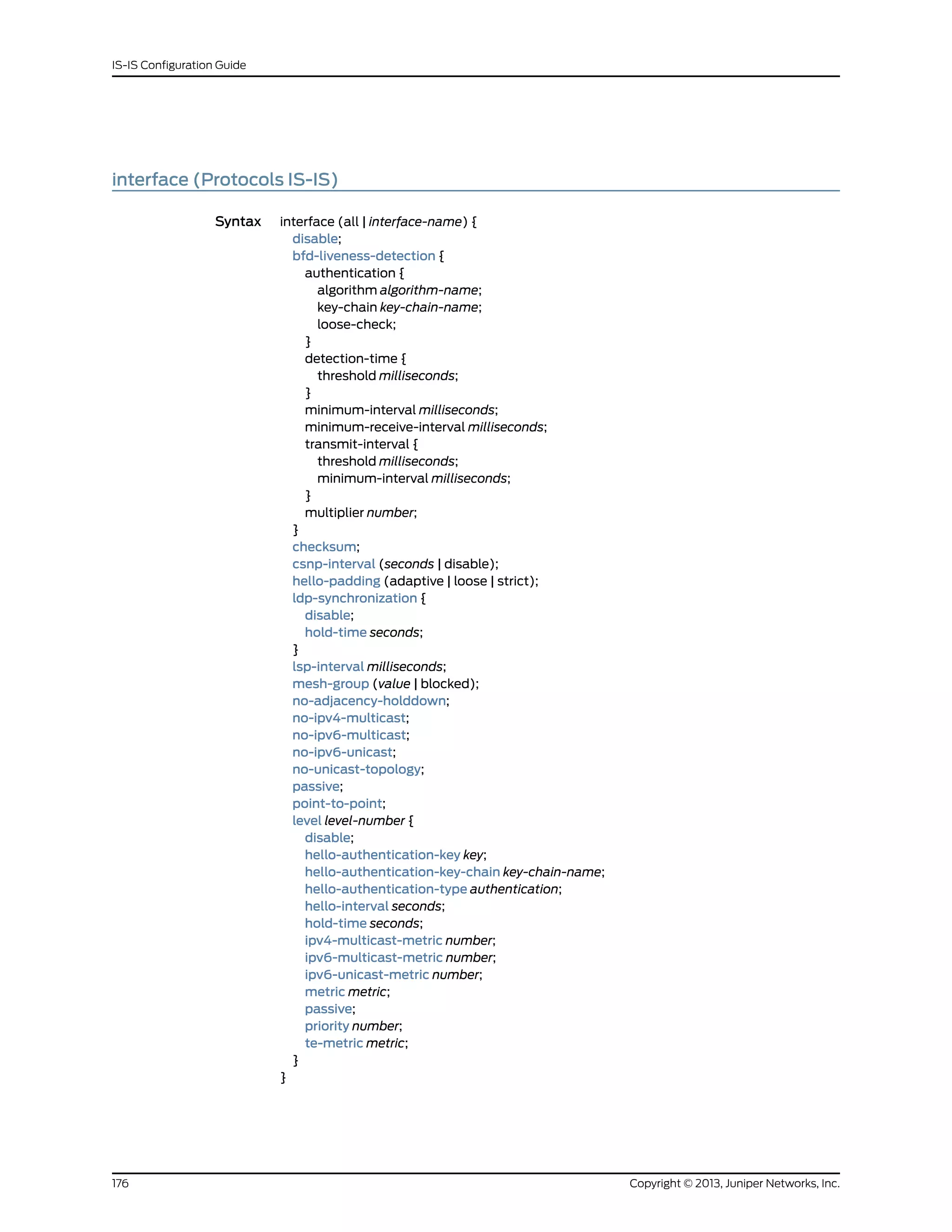
![Hierarchy Level [edit logical-systems logical-system-name protocols isis],
[editlogical-systemslogical-system-namerouting-instancesrouting-instance-nameprotocols
isis],
[edit protocols isis],
[edit routing-instances routing-instance-name protocols isis]
Release Information Statement introduced before Junos OS Release 7.4.
Statement introduced in Junos OS Release 9.0 for EX Series switches.
Statement introduced in Junos OS Release 12.1 for the QFX Series.
Description Configure interface-specific IS-IS properties. To configure more than one interface, include
the interface statement multiple times.
Enabling IS-IS on an interface (by including the interface statement at the [edit protocols
isis] or the [edit routing-instances routing-instance-name protocols isis] hierarchy level),
disabling it (by including the disable statement), and not actually having IS-IS run on an
interface (by including the passive statement) are mutually exclusive states.
Options all—Have Junos OS create IS-IS interfaces automatically.
interface-name—Name of an interface. Specify the full interface name, including the
physical and logical address components.
The remaining statements are explained separately.
Required Privilege
Level
routing—To view this statement in the configuration.
routing-control—To add this statement to the configuration.
Related
Documentation
• IS-IS Configuration Guide
177Copyright © 2013, Juniper Networks, Inc.
Chapter 5: Configuration Statements](https://image.slidesharecdn.com/config-guide-routing-is-is-151104131021-lva1-app6891/75/Juniper-MX-Config-guide-routing-is-is-197-2048.jpg)
![ipv4-multicast
Syntax ipv4-multicast;
Hierarchy Level [edit logical-systems logical-system-name protocols isis topologies],
[editlogical-systemslogical-system-namerouting-instancesrouting-instance-nameprotocols
isis topologies],
[edit protocols isis topologies],
[edit routing-instances routing-instance-name protocols isis topologies]
Release Information Statement introduced before Junos OS Release 7.4.
Statement introduced in Junos OS Release 9.0 for EX Series switches.
Statement introduced in Junos OS Release 12.1 for the QFX Series.
Description Configure alternate IPv4 multicast topologies.
Default Multicast topologies are disabled.
Required Privilege
Level
routing—To view this statement in the configuration.
routing-control—To add this statement to the configuration.
Related
Documentation
• Example: Configuring IS-IS Multicast Topology on page 75
ipv4-multicast-metric
Syntax ipv4-multicast-metric metric;
Hierarchy Level [edit logical-systems logical-system-name protocols isis interface interface-namelevel
level-number],
[editlogical-systemslogical-system-namerouting-instancesrouting-instance-nameprotocols
isis interface interface-name level level-number],
[edit protocols isis interface interface-name level level-number],
[edit routing-instances routing-instance-name protocols isis interface interface-name level
level-number]
Release Information Statement introduced before Junos OS Release 7.4.
Statement introduced in Junos OS Release 9.0 for EX Series switches.
Statement introduced in Junos OS Release 12.1 for the QFX Series.
Description Specify the multicast topology metric value for the level.
Options metric—Metric value.
Range: 0 through 16,777,215
Required Privilege
Level
routing—To view this statement in the configuration.
routing-control—To add this statement to the configuration.
Related
Documentation
• Example: Configuring IS-IS Multicast Topology on page 75
Copyright © 2013, Juniper Networks, Inc.178
IS-IS Configuration Guide](https://image.slidesharecdn.com/config-guide-routing-is-is-151104131021-lva1-app6891/75/Juniper-MX-Config-guide-routing-is-is-198-2048.jpg)
![ipv6-multicast
Syntax ipv6-multicast;
Hierarchy Level [edit logical-systems logical-system-name protocols isis topologies],
[editlogical-systemslogical-system-namerouting-instancesrouting-instance-nameprotocols
isis topologies],
[edit protocols isis topologies],
[edit routing-instances routing-instance-name protocols isis topologies]
Release Information Statement introduced before Junos OS Release 7.4.
Statement introduced in Junos OS Release 9.0 for EX Series switches.
Description Configure alternate IPv6 multicast topologies.
Default Multicast topologies are disabled.
Required Privilege
Level
routing—To view this statement in the configuration.
routing-control—To add this statement to the configuration.
Related
Documentation
• Example: Configuring IS-IS Multicast Topology on page 75
ipv6-multicast-metric
Syntax ipv6-multicast-metric metric;
Hierarchy Level [edit logical-systems logical-system-name protocols isis interface interface-name level
level-number],
[editlogical-systemslogical-system-namerouting-instancesrouting-instance-nameprotocols
isis interface interface-name level level-number],
[edit protocols isis interface interface-name level level-number],
[edit routing-instances routing-instance-name protocols isis interface interface-name level
level-number]
Release Information Statement introduced before Junos OS Release 7.4.
Statement introduced in Junos OS Release 9.0 for EX Series switches.
Description Specify the IPv6 alternate multicast topology metric value for the level.
Options metric—Metric value.
Range: 0 through 16,777,215
Required Privilege
Level
routing—To view this statement in the configuration.
routing-control—To add this statement to the configuration.
Related
Documentation
• Example: Configuring IS-IS Multicast Topology on page 75
179Copyright © 2013, Juniper Networks, Inc.
Chapter 5: Configuration Statements](https://image.slidesharecdn.com/config-guide-routing-is-is-151104131021-lva1-app6891/75/Juniper-MX-Config-guide-routing-is-is-199-2048.jpg)
![ipv6-unicast
Syntax ipv6-unicast;
Hierarchy Level [edit logical-systems logical-system-name protocols isis topologies],
[editlogical-systemslogical-system-namerouting-instancesrouting-instance-nameprotocols
isis topologies],
[edit protocols isis topologies],
[edit routing-instances routing-instance-name protocols isis topologies]
Release Information Statement introduced before Junos OS Release 7.4.
Statement introduced in Junos OS Release 9.0 for EX Series switches.
Description Configure alternate IPv6 unicast topologies.
This statement causes IS-IS to calculate an alternate IPv6 unicast topology, in addition
to the normal IPv4 unicast topology, and add the corresponding routes to inet6.0.
Default IPv6 unicast topologies are disabled.
Required Privilege
Level
routing—To view this statement in the configuration.
routing-control—To add this statement to the configuration.
Related
Documentation
• Configuring IS-IS IPv6 Unicast Topologies on page 122
Copyright © 2013, Juniper Networks, Inc.180
IS-IS Configuration Guide](https://image.slidesharecdn.com/config-guide-routing-is-is-151104131021-lva1-app6891/75/Juniper-MX-Config-guide-routing-is-is-200-2048.jpg)
![ipv6-unicast-metric
Syntax ipv6-unicast-metric metric;
Hierarchy Level [edit logical-systems logical-system-name protocols isis interface interface-name level
level-number],
[editlogical-systemslogical-system-namerouting-instancesrouting-instance-nameprotocols
isis interface interface-name level level-number],
[edit protocols isis interface interface-name level level-number],
[edit routing-instances routing-instance-name protocols isis interface interface-name level
level-number]
Release Information Statement introduced before Junos OS Release 7.4.
Statement introduced in Junos OS Release 9.0 for EX Series switches.
Description Specify the IPv6 unicast topology metric value for the level. The IS-IS interface metrics
for the IPv4 topology can be configured independently of the IPv6 metrics.
Options metric—Metric value.
Range: 0 through 16,777,215
Required Privilege
Level
routing—To view this statement in the configuration.
routing-control—To add this statement to the configuration.
Related
Documentation
• Configuring IS-IS IPv6 Unicast Topologies on page 122
181Copyright © 2013, Juniper Networks, Inc.
Chapter 5: Configuration Statements](https://image.slidesharecdn.com/config-guide-routing-is-is-151104131021-lva1-app6891/75/Juniper-MX-Config-guide-routing-is-is-201-2048.jpg)
![isis
Syntax isis { ... }
Hierarchy Level [edit logical-systems logical-system-name protocols],
[edit logical-systems logical-system-name routing-instances routing-instance-name
protocols],
[edit protocols],
[edit routing-instances routing-instance-name protocols]
Release Information Statement introduced before Junos OS Release 7.4.
Statement introduced in Junos OS Release 9.0 for EX Series switches.
Statement introduced in Junos OS Release 12.1 for the QFX Series.
Description Enable IS-IS routing on the routing device or for a routing instance.
The isis statement is the one statement you must include in the configuration to run IS-IS
on the routing device or in a routing instance.
Default IS-IS is disabled on the routing device.
Required Privilege
Level
routing—To view this statement in the configuration.
routing-control—To add this statement to the configuration.
Related
Documentation
• Example: Configuring IS-IS on page 15
• Example: Configuring Multi-Level IS-IS on page 20
Copyright © 2013, Juniper Networks, Inc.182
IS-IS Configuration Guide](https://image.slidesharecdn.com/config-guide-routing-is-is-151104131021-lva1-app6891/75/Juniper-MX-Config-guide-routing-is-is-202-2048.jpg)
![label-switched-path (Protocols IS-IS)
Syntax label-switched-path name level level-number metric metric;
Hierarchy Level [edit logical-systems logical-system-name protocols isis],
[editlogical-systemslogical-system-namerouting-instancesrouting-instance-nameprotocols
isis],
[edit protocols isis],
[edit routing-instances routing-instance-name protocols isis]
Release Information Statement introduced before Junos OS Release 7.4.
Description Advertise LSPs into IS-IS as point-to-point links. The LSP is advertised in the appropriate
IS-IS levels as a point-to-point link and contains a local address and a remote address.
When you advertise label-switched paths into IS-IS as point-to-point links, the
label-switched paths are used in SPF calculations. The advertisement contains a local
address (the from address of the label-switched path), a remote address (the to address
of the label-switched path), and a metric.
Before a single-hop label-switched path between a multiaccess link can be announced
as up and used in SPF calculations, you must configure a label-switched path in both
directions between two label-switched routers.
Options name—Identifies the LSP.
level-number—IS-IS level number.
Values: 1 or 2
metric—Metric value.
Range: 1 through 63, or 1 through 16,777,215 (if you have configured wide metrics)
Default: 0 (for lo0), 10 (for all other interfaces)
Required Privilege
Level
routing—To view this statement in the configuration.
routing-control—To add this statement to the configuration.
Related
Documentation
• Advertising Label-Switched Paths into IS-IS on page 130
183Copyright © 2013, Juniper Networks, Inc.
Chapter 5: Configuration Statements](https://image.slidesharecdn.com/config-guide-routing-is-is-151104131021-lva1-app6891/75/Juniper-MX-Config-guide-routing-is-is-203-2048.jpg)
![LDP-synchronization
Syntax ldp-synchronization {
disable;
hold-time seconds;
}
Hierarchy Level [edit logical-systems logical-system-name protocols isis interface interface-name],
[editlogical-systemslogical-system-namerouting-instancesrouting-instance-nameprotocols
isis interface interface-name],
[edit protocols isis interface interface-name],
[edit routing-instances routing-instance-name protocols isis interface interface-name]
Release Information Statement introduced in Junos OS Release 7.5.
Description Enable synchronization by advertising the maximum cost metric until LDP is operational
on the link.
LDP distributes labels in non-traffic-engineered applications. Labels are distributed along
the best path determined by IS-IS. If the synchronization between LDP and IS-IS is lost,
the label-switched path (LSP) goes down. Therefore, LDP and IS-IS synchronization is
beneficial. When LDP synchronization is configured and when LDP is not fully operational
on a given link (a session is not established and labels are not exchanged), IS-IS advertises
the link with the maximum cost metric. The link is not preferred but remains in the network
topology.
LDP synchronization is supported only on point-to-point interfaces and LAN interfaces
configured as point-to-point interfaces under IS-IS. LDP synchronization is not supported
during graceful restart.
To advertise the maximum cost metric until LDP is operational for LDP synchronization,
include the ldp-synchronization statement.
To disable synchronization, include the disable statement. To configure the time period
to advertise the maximum cost metric for a link that is not fully operational, include the
hold-time statement.
NOTE: When an interface has been in the holddown state for more than
3 minutes, a system log message with a warning level is sent. This message
appears in both the messages file and the trace file.
The remaining statements are explained separately.
Required Privilege
Level
routing—To view this statement in the configuration.
routing-control—To add this statement to the configuration.
Related
Documentation
• Example: Configuring Synchronization Between LDP and IGPs
Copyright © 2013, Juniper Networks, Inc.184
IS-IS Configuration Guide](https://image.slidesharecdn.com/config-guide-routing-is-is-151104131021-lva1-app6891/75/Juniper-MX-Config-guide-routing-is-is-204-2048.jpg)
![level (Global IS-IS)
Syntax level level-number {
authentication-key key;
authentication-key-chain (Protocols IS-IS) key-chain-name;
authentication-type type;
external-preference preference;
no-csnp-authentication;
no-hello-authentication;
no-psnp-authentication;
preference preference;
wide-metrics-only;
}
Hierarchy Level [edit logical-systems logical-system-name protocols isis],
[editlogical-systemslogical-system-namerouting-instancesrouting-instance-nameprotocols
isis],
[edit protocols isis],
[edit routing-instances routing-instance-name protocols isis]
Release Information Statement introduced before Junos OS Release 7.4.
Statement introduced in Junos OS Release 9.0 for EX Series switches.
Statement introduced in Junos OS Release 12.1 for the QFX Series.
Description Configure the global-level properties.
You can administratively divide a single AS into smaller groups called areas. You configure
each routing device interface to be in an area. Any interface can be in any area. The area
address applies to the entire routing device; you cannot specify one interface to be in one
area and another interface in a different area. In order to route between areas you must
have two adjacent Level 2 routers that communicate with each other.
Level 1 routers can only route within their IS-IS area. To send traffic outside their area,
Level 1 routers must send packets to the nearest intra-area Level 2 router. A routing device
can be a Level 1 router, a Level 2 router, or both. You specify the router level on a
per-interface basis, and a routing device becomes adjacent to other routing devices on
the same level on that link only.
You can configure one Level 1 routing process and one Level 2 routing process on each
interface, and you can configure the two levels differently.
Options level-number—IS-IS level number.
Values: 1 or 2
The remaining statements are explained separately.
Required Privilege
Level
routing—To view this statement in the configuration.
routing-control—To add this statement to the configuration.
Related
Documentation
• Configuring Preference Values for IS-IS Routes on page 129
185Copyright © 2013, Juniper Networks, Inc.
Chapter 5: Configuration Statements](https://image.slidesharecdn.com/config-guide-routing-is-is-151104131021-lva1-app6891/75/Juniper-MX-Config-guide-routing-is-is-205-2048.jpg)
![level (IS-IS Interfaces)
Syntax level level-number {
level (IS-IS Interfaces);
hello-authentication-key key;
hello-authentication-key-chain key-chain-name;
hello-authentication-type authentication;
hello-interval seconds;
hold-time seconds;
ipv4-multicast-metric number;
ipv6-unicast-metric number;
metric metric;
passive;
priority number;
te-metric metric;
}
Hierarchy Level [edit logical-systems logical-system-name protocols isis interface interface-name],
[editlogical-systemslogical-system-namerouting-instancesrouting-instance-nameprotocols
isis interface interface-name],
[edit protocols isis interface interface-name],
[edit routing-instances routing-instance-name protocols isis interface interface-name]
Release Information Statement introduced before Junos OS Release 7.4.
Statement introduced in Junos OS Release 9.0 for EX Series switches.
Description Configure the IS-IS level. You can configure one instance of Level 1 routing and one
instance of Level 2 routing on each interface, and you can configure the two levels
differently.
Options level-number—IS-IS level number.
Values: 1 or 2
Default: The routing device operates as both a Level 1 and Level 2 router.
The remaining statements are explained separately.
Required Privilege
Level
routing—To view this statement in the configuration.
routing-control—To add this statement to the configuration.
Related
Documentation
• Configuring Levels on IS-IS Interfaces on page 122
Copyright © 2013, Juniper Networks, Inc.186
IS-IS Configuration Guide](https://image.slidesharecdn.com/config-guide-routing-is-is-151104131021-lva1-app6891/75/Juniper-MX-Config-guide-routing-is-is-206-2048.jpg)
![link-protection (Protocols IS-IS)
Syntax link-protection;
Hierarchy Level [edit logical-systems logical-system-name protocols isis interface interface-name],
[editlogical-systemslogical-system-namerouting-instancesrouting-instance-nameprotocols
isis interface interface-name],
[edit protocols isis interface interface-name],
[edit routing-instances routing-instance-name protocols isis interface interface-name]
Release Information Statement introduced in Junos OS Release 9.5.
Statement introduced in Junos OS Release 9.0 for EX Series switches.
Statement introduced in Junos OS Release 12.1 for the QFX Series.
Description Enable link protection on the specified IS-IS interface. Junos OS creates a backup loop-free
alternate path to the primary next hop for all destination routes that traverse the protected
interface.
Required Privilege
Level
routing—To view this statement in the configuration.
routing-control—To add this statement to the configuration.
Related
Documentation
• node-link-protection on page 206
• Example: Configuring Link and Node Protection for IS-IS Routes on page 91
loose-authentication-check
Syntax loose-authentication-check;
Hierarchy Level [edit logical-systems logical-system-name protocols isis],
[editlogical-systemslogical-system-namerouting-instancesrouting-instance-nameprotocols
isis],
[edit protocols isis],
[edit routing-instances routing-instance-name protocols isis]
Release Information Statement introduced before Junos OS Release 7.4.
Statement introduced in Junos OS Release 9.0 for EX Series switches.
Statement introduced in Junos OS Release 12.1 for the QFX Series.
Description Allow the use of MD5 authentication without requiring network-wide deployment.
Required Privilege
Level
routing—To view this statement in the configuration.
routing-control—To add this statement to the configuration.
Related
Documentation
• Enabling Authentication for IS-IS Without Network-Wide Deployment on page 137
187Copyright © 2013, Juniper Networks, Inc.
Chapter 5: Configuration Statements](https://image.slidesharecdn.com/config-guide-routing-is-is-151104131021-lva1-app6891/75/Juniper-MX-Config-guide-routing-is-is-207-2048.jpg)
![lsp-equal-cost
Syntax lsp-equal-cost;
Hierarchy Level [edit logical-systems logical-system-name protocols isis traffic-engineering multipath],
[edit protocols isis traffic-engineering multipath]
Release Information Statement introduced in Junos OS Release 9.6.
Description Configure label-switched paths (LSPs) to be retained as equal cost paths for load
balancing when a better path metric is found during the IS-IS internal routing table
calculation.
When a route with an improved metric is added to the IS-IS internal routing table, IS-IS
flushes all next-hop information (including LSP next-hop information) for a route. This
is undesirable, because certain equal-cost multipath (ECMP) combinations can be lost
during route calculation. To override this default IS-IS behavior, include the lsp-equal-cost
statement for load balancing, so that the equal cost path information is retained in the
routing table.
Required Privilege
Level
routing—To view this statement in the configuration.
routing-control—To add this statement to the configuration.
Related
Documentation
• Configuring IS-IS Traffic Engineering Attributes on page 133
• multipath on page 197 (IS-IS)
• traffic-engineering on page 228
Copyright © 2013, Juniper Networks, Inc.188
IS-IS Configuration Guide](https://image.slidesharecdn.com/config-guide-routing-is-is-151104131021-lva1-app6891/75/Juniper-MX-Config-guide-routing-is-is-208-2048.jpg)
![lsp-interval
Syntax lsp-interval milliseconds;
Hierarchy Level [edit logical-systems logical-system-name protocols isis interface interface-name],
[editlogical-systemslogical-system-namerouting-instancesrouting-instance-nameprotocols
isis interface interface-name],
[edit protocols isis interface interface-name],
[edit routing-instances routing-instance-name protocols isis interface interface-name]
Release Information Statement introduced before Junos OS Release 7.4.
Statement introduced in Junos OS Release 9.0 for EX Series switches.
Statement introduced in Junos OS Release 12.1 for the QFX Series.
Description Configure the link-state PDU interval time.
To disable the transmission of all link-state PDU packets, set the interval to 0.
LSP throttling by use of the lsp-interval statement controls the flooding pace to
neighboring routing devices in order to not overload them.
Also, consider that control traffic (such as link-state PDU packets and related packets)
might delay user traffic (information packets) because control traffic always has
precedence in terms of scheduling on the routing device interface cards. Unfortunately,
the control traffic transmission rate is not decreased on low-bandwidth interfaces, such
as DS-0 or fractional T1 and E1 interface. Line control traffic stays the same. On a
low-bandwidth circuit that is transmitting 30 full-MTU-sized packets, there is not much
bandwidth left over for other types of packets.
Default By default, the routing device sends one link-state PDU packet out an interface every
100 milliseconds.
Options milliseconds—Number of milliseconds between the sending of link-state PDUs. Specifying
a value of 0 blocks all link-state PDU transmission.
Range: 0 through 1000 milliseconds
Default: 100 milliseconds
Required Privilege
Level
routing—To view this statement in the configuration.
routing-control—To add this statement to the configuration.
Related
Documentation
• Configuring the Transmission Frequency for Link-State PDUs on IS-IS Interfaces on
page 120
189Copyright © 2013, Juniper Networks, Inc.
Chapter 5: Configuration Statements](https://image.slidesharecdn.com/config-guide-routing-is-is-151104131021-lva1-app6891/75/Juniper-MX-Config-guide-routing-is-is-209-2048.jpg)
![lsp-lifetime
Syntax lsp-lifetime seconds;
Hierarchy Level [edit logical-systems logical-system-name protocols isis],
[editlogical-systemslogical-system-namerouting-instancesrouting-instance-nameprotocols
isis],
[edit protocols isis],
[edit routing-instances routing-instance-name protocols isis]
Release Information Statement introduced before Junos OS Release 7.4.
Statement introduced in Junos OS Release 9.0 for EX Series switches.
Statement introduced in Junos OS Release 12.1 for the QFX Series.
Description Specify how long a link-state PDU originating from the routing device should persist in
the network. The routing device sends link-state PDUs often enough so that the link-state
PDU lifetime never expires.
Becasue link-state PDUs have a maximum lifetime, they need to be refreshed. Refreshing
means that a router needs to re-originate its link-state PDUs periodically. The
re-origination interval must be less than the link-state PDU’s lifetime. For example, if the
link-state PDU is valid for 1200 seconds, the routing device needs to refresh the link-state
PDU in less than 1200 seconds to avoid removal of the link-state PDU from the link-state
databasebyotherroutingdevices.Therecommendedmaximumlink-statePDUorigination
interval is the lifetime minus 300 seconds. So, in a default environment this would be
900 seconds. In Junos OS, the refresh interval is derived from the lifetime and is equal
to the lifetime minus 317 seconds. You can change the lifetime to a higher value to reduce
the number of refreshes in the network. (You would rarely want to increase the number
of refreshes.) Often theses periodic link-state PDU refreshes are referred to as refresh
noise, and network administrators want to reduce this noise as much as possible.
The show isis overview command displays the link-state PDU lifetime.
Default By default, link-state PDUs are maintained in network databases for 1200 seconds
(20 minutes) before being considered invalid. This length of time, called the LSP lifetime,
normally is sufficient to guarantee that link-state PDUs never expire.
Options seconds—link-state PDU lifetime, in seconds.
Range: 350 through 65,535 seconds
Default: 1200 seconds
Required Privilege
Level
routing—To view this statement in the configuration.
routing-control—To add this statement to the configuration.
Related
Documentation
• Configuring the Link-State PDU Lifetime for IS-IS on page 129
• http://www.juniper.net/us/en/training/certification/JNCIP_studyguide.pdf
Copyright © 2013, Juniper Networks, Inc.190
IS-IS Configuration Guide](https://image.slidesharecdn.com/config-guide-routing-is-is-151104131021-lva1-app6891/75/Juniper-MX-Config-guide-routing-is-is-210-2048.jpg)
![max-areas
Syntax max-areas number;
Hierarchy Level [edit logical-systems logical-system-name protocols isis],
[editlogical-systemslogical-system-namerouting-instancesrouting-instance-nameprotocols
isis]
[edit protocols isis],
[edit routing-instances routing-instance-name protocols isis]
Release Information Statement introduced in Junos OS Release 8.1.
Statement introduced in Junos OS Release 9.0 for EX Series switches.
Statement introduced in Junos OS Release 12.1 for the QFX Series.
Description Modify the maximum number of IS-IS areas advertised.
This value is included in the Maximum Address Area field of the IS-IS common PDU
header included in all outgoing PDUs.
The maximum number of areas you can advertise is restricted to 36 to ensure that the
IIH PDUs have enough space to include other type, length, and value (TLV) fields, such
as the Authentication and IPv4 and IPv6 Interface Address TLVs.
Options number—Maximum number of areas to include in the IS-IS hello (IIH) PDUs and link-state
PDUs.
Range: 3 through 36
Default: 3
Required Privilege
Level
routing—To view this statement in the configuration.
routing-control—To add this statement to the configuration.
Related
Documentation
• Limiting the Number of Advertised IS-IS Areas on page 128
191Copyright © 2013, Juniper Networks, Inc.
Chapter 5: Configuration Statements](https://image.slidesharecdn.com/config-guide-routing-is-is-151104131021-lva1-app6891/75/Juniper-MX-Config-guide-routing-is-is-211-2048.jpg)
![max-hello-size
Syntax max-hello-size size;
Hierarchy Level [edit logical-systems logical-system-name protocols isis],
[editlogical-systemslogical-system-namerouting-instancesrouting-instance-nameprotocols
isis],
[edit protocols isis],
[edit routing-instances routing-instance-name protocols isis]
Release Information Statement introduced in Junos OS Release 12.1.
Description Modify the maximum size of IS-IS hello packets.
Options size—Maximum size allocated for IS-IS hello packets.
Range: 512 through 1492 bytes
Default: 1492 bytes
Required Privilege
Level
routing—To view this statement in the configuration.
routing-control—To add this statement to the configuration.
Related
Documentation
• Limiting the Size of IS-IS Hello Packets on page 138
max-lsp-size
Syntax max-lsp-size size;
Hierarchy Level [edit logical-systems logical-system-name protocols isis],
[editlogical-systemslogical-system-namerouting-instancesrouting-instance-nameprotocols
isis],
[edit protocols isis],
[edit routing-instances routing-instance-name protocols isis]
Release Information Statement introduced in Junos OS Release 12.1.
Description Modify the maximum size of IS-IS link-state PDUs.
Options size—Maximum size allocated for IS-IS link-state PDUs.
Range: 512 through 1492 bytes
Default: 1492 bytes
Required Privilege
Level
routing—To view this statement in the configuration.
routing-control—To add this statement to the configuration.
Related
Documentation
• Limiting the Size of IS-IS Link-State PDUs on page 138
Copyright © 2013, Juniper Networks, Inc.192
IS-IS Configuration Guide](https://image.slidesharecdn.com/config-guide-routing-is-is-151104131021-lva1-app6891/75/Juniper-MX-Config-guide-routing-is-is-212-2048.jpg)
![max-snp-size
Syntax max-snp-size size;
Hierarchy Level [edit logical-systems logical-system-name protocols isis],
[editlogical-systemslogical-system-namerouting-instancesrouting-instance-nameprotocols
isis],
[edit protocols isis],
[edit routing-instances routing-instance-name protocols isis]
Release Information Statement introduced in Junos OS Release 12.1.
Description Modify the maximum size of partial or complete IS-IS sequence number packets.
Options size—Maximum size allocated for sequence number of partial or complete IS-IS packets.
Range: 512 through 1400 bytes
Default: 1400 bytes
Required Privilege
Level
routing—To view this statement in the configuration.
routing-control—To add this statement to the configuration.
Related
Documentation
• Limiting the Size of IS-IS Sequence Number Packets on page 139
193Copyright © 2013, Juniper Networks, Inc.
Chapter 5: Configuration Statements](https://image.slidesharecdn.com/config-guide-routing-is-is-151104131021-lva1-app6891/75/Juniper-MX-Config-guide-routing-is-is-213-2048.jpg)
![mesh-group (Protocols IS-IS)
Syntax mesh-group (blocked | value);
Hierarchy Level [edit logical-systems logical-system-name protocols isis interface interface-name],
[editlogical-systemslogical-system-namerouting-instancesrouting-instance-nameprotocols
isis interface interface-name],
[edit protocols isis interface interface-name],
[edit routing-instances routing-instance-name protocols isis interface interface-name]
Release Information Statement introduced before Junos OS Release 7.4.
Statement introduced in Junos OS Release 9.0 for EX Series switches.
Statement introduced in Junos OS Release 12.1 for the QFX Series.
Description Configure an interface to be part of a mesh group, which is a set of fully connected nodes.
A mesh group is a set of routing devices that are fully connected; that is, they have a fully
meshed topology. When link-state PDU packets are being flooded throughout an area,
each router within a mesh group receives only a single copy of a link-state PDU packet
instead of receiving one copy from each neighbor, thus minimizing the overhead associated
with the flooding of link-state PDU packets.
To create a mesh group and designate that an interface be part of the group, assign a
mesh-group number to all the routing device interfaces in the group. To prevent an
interface in the mesh group from flooding link-state PDUs, configure blocking on that
interface.
Options blocked—Configure the interface so that it does not flood link-state PDU packets.
value—Number that identifies the mesh group.
Range: 1 through 4,294,967,295 (2
32
– 1; 32 bits are allocated to identify a mesh group)
Required Privilege
Level
routing—To view this statement in the configuration.
routing-control—To add this statement to the configuration.
Related
Documentation
• Configuring Mesh Groups of IS-IS Interfaces on page 121
Copyright © 2013, Juniper Networks, Inc.194
IS-IS Configuration Guide](https://image.slidesharecdn.com/config-guide-routing-is-is-151104131021-lva1-app6891/75/Juniper-MX-Config-guide-routing-is-is-214-2048.jpg)
![metric (Protocols IS-IS)
Syntax metric metric;
Hierarchy Level [edit logical-systems logical-system-name protocols isis interface interface-name level
level-number],
[editlogical-systemslogical-system-namerouting-instancesrouting-instance-nameprotocols
isis interface interface-name level level-number],
[edit protocols isis interface interface-name level level-number],
[edit routing-instances routing-instance-name protocols isis interface interface-name level
level-number]
Release Information Statement introduced before Junos OS Release 7.4.
Statement introduced in Junos OS Release 9.0 for EX Series switches.
Statement introduced in Junos OS Release 12.1 for the QFX Series.
Description Specify the metric value for the level.
All IS-IS routes have a cost, which is a routing metric that is used in the IS-IS link-state
calculation. The cost is an arbitrary, dimensionless integer that can be from 1 through 63,
or from 1 through 16,777,215 (2
24
– 1) if you are using wide metrics.
Similar to other routing protocols, IS-IS provides a way of exporting routes from the
routing table into the IS-IS network. When a route is exported into the IS-IS network
without a specified metric, IS-IS uses default metric values for the route, depending on
the protocol that was used to learn the route.
Table 7 on page 126 depicts IS-IS route export metric default values.
Table 8: Default Metric Values for Routes Exported into IS-IS
Default Metric ValueProtocol Used for Learning the Route
10Direct
Same as reported by the protocol used for exporting the routeStatic
10Aggregate
10Generate
Same as reported by the protocol used for exporting the routeRIP
Same as reported by the protocol used for exporting the routeOSPF
10BGP
The default metric values behavior can be customized by using routing policies.
Options metric—Metric value.
Range: 1 through 63, or 1 through 16,777,215 (if you have configured wide metrics)
195Copyright © 2013, Juniper Networks, Inc.
Chapter 5: Configuration Statements](https://image.slidesharecdn.com/config-guide-routing-is-is-151104131021-lva1-app6891/75/Juniper-MX-Config-guide-routing-is-is-215-2048.jpg)
![Default: 10 (for all interfaces except lo0), 0 (for the lo0 interface)
Required Privilege
Level
routing—To view this statement in the configuration.
routing-control—To add this statement to the configuration.
Related
Documentation
• Configuring the Reference Bandwidth Used in IS-IS Metric Calculations on page 127
• te-metric on page 223
• wide-metrics-only on page 231
multicast-rpf-routes
Syntax multicast-rpf-routes;
Hierarchy Level [edit logical-systems logical-system-name protocols isis traffic-engineering family inet
shortcuts],
[edit logical-systems logical-system-name routing-instances traffic-engineering family inet
shortcuts],
[edit protocols isis traffic-engineering family inet shortcuts],
[edit routing-instances routing-instance-name protocols isis traffic-engineering family inet
shortcuts]
Release Information Statement introduced in Junos OS Release 9.3.
Description Install unicast IPv4 routes into the multicast routing table (inet.2) for multicast
reverse-path forwarding (RPF) checks.
Traffic engineering shortcuts must be enabled. IPv4 multicast topology must not be
enabled. LSPs must not be advertised into IS-IS.
Required Privilege
Level
routing—To view this statement in the configuration.
routing-control—To add this statement to the configuration.
Related
Documentation
• Installing IPv4 Routes into the Multicast Routing Table on page 136
Copyright © 2013, Juniper Networks, Inc.196
IS-IS Configuration Guide](https://image.slidesharecdn.com/config-guide-routing-is-is-151104131021-lva1-app6891/75/Juniper-MX-Config-guide-routing-is-is-216-2048.jpg)
![multipath (Protocols IS-IS)
Syntax multipath {
lsp-equal-cost;
}
Hierarchy Level [edit logical-systems logical-system-name protocols isistraffic-engineering],
[edit protocols isistraffic-engineering]
Release Information Statement introduced in Junos OS Release 9.6.
Description Enable load balancing for multiple label-switched paths (LSPs).
Options lsp-equal-cost—Configure LSPs to be retained as equal cost paths for load balancing
when a better route metric is added to the routing table.
When a route with an improved metric is added to the IS-IS internal routing table,
IS-IS flushes all next-hop information (including LSP next-hop information) for a
route. This is undesirable, because certain equal-cost multipath (ECMP) path
combinations can be lost during route calculation. To override this default IS-IS
behavior, include the lsp-equal-cost statement for load balancing, so that the equal
cost path information is retained in the routing table.
Required Privilege
Level
routing—To view this statement in the configuration.
routing-control—To add this statement to the configuration.
Related
Documentation
• Configuring IS-IS Traffic Engineering Attributes on page 133
• lsp-equal-cost on page 188
• multipath (BGP)
• multipath (protocol independent)
• traffic-engineering on page 228
197Copyright © 2013, Juniper Networks, Inc.
Chapter 5: Configuration Statements](https://image.slidesharecdn.com/config-guide-routing-is-is-151104131021-lva1-app6891/75/Juniper-MX-Config-guide-routing-is-is-217-2048.jpg)
![no-adjacency-down-notification (Protocols IS-IS)
Syntax no-adjacency-down-notification;
Hierarchy Level [edit logical-systems logical-system-name protocols isis interface interface-name],
[edit protocols isis interface interface-name]
Release Information Statement introduced in Junos OS Release 8.0.
Description Disable adjacency down notification for IS-IS to allow for migration from IS-IS to OSPF
without disruption of the RSVP neighbors and associated RSVP-signaled LSPs.
Whenever IS-IS is deactivated, the IS-IS adjacencies are brought down. IS-IS signals to
RSVP to bring down any RSVP neighbors associated with the IS-IS adjacencies, and this
further causes the associated LSPs signaled by RSVP to go down as well.
A similar process occurs whenever OSPF is deactivated. The OSPF neighbors are brought
down. OSPF signals to RSVP to bring down any of the RSVP neighbors associated with
the OSPF neighbors, and this further causes the associated LSPs signaled by RSVP to
go down as well.
If you need to migrate from IS-IS to OSPF or from OSPF to IS-IS, the IGP notification to
RSVP for an adjacency or neighbor down event needs to be ignored. Using the
no-adjacency-down-notification or no-neighbor-down-notification statements, you can
disable IS-IS adjacency down notification or OSPF neighbor down notification,
respectively, until the migration is complete. The network administrator is responsible
for configuring the statements before the migration, and then removing them from the
configuration afterward, so that IGP notification can function normally.
Required Privilege
Level
routing—To view this statement in the configuration.
routing-control—To add this statement to the configuration.
Related
Documentation
• Disabling Adjacency Down and Neighbor Down Notification in IS-IS and OSPF on
page 145
• no-neighbor-down-notification
Copyright © 2013, Juniper Networks, Inc.198
IS-IS Configuration Guide](https://image.slidesharecdn.com/config-guide-routing-is-is-151104131021-lva1-app6891/75/Juniper-MX-Config-guide-routing-is-is-218-2048.jpg)
![no-adjacency-holddown
Syntax no-adjacency-holddown;
Hierarchy Level [edit logical-systems logical-system-name protocols isis],
[editlogical-systemslogical-system-namerouting-instancesrouting-instance-nameprotocols
isis],
[edit protocols isis],
[edit routing-instances routing-instance-name protocols isis]
Release Information Statement introduced in Junos OS Release 8.0.
Statement introduced in Junos OS Release 9.0 for EX Series switches.
Statement introduced in Junos OS Release 12.1 for the QFX Series.
Description Disable the hold-down timer for IS-IS adjacencies.
A hold-down timer delays the advertising of adjacencies by waiting until a time period
has elapsed before labeling adjacencies in the up state. You can disable this hold-down
timer, which labels adjacencies up faster. However, disabling the hold-down timer creates
more frequent link-state PDU updates and SPF computation.
Required Privilege
Level
routing—To view this statement in the configuration.
routing-control—To add this statement to the configuration.
Related
Documentation
• Configuring Quicker Advertisement of IS-IS Adjacency State Changes on page 137
no-authentication-check
Syntax no-authentication-check;
Hierarchy Level [edit logical-systems logical-system-name protocols isis],
[editlogical-systemslogical-system-namerouting-instancesrouting-instance-nameprotocols
isis],
[edit protocols isis],
[edit routing-instances routing-instance-name protocols isis]
Release Information Statement introduced before Junos OS Release 7.4.
Statement introduced in Junos OS Release 9.0 for EX Series switches.
Statement introduced in Junos OS Release 12.1 for the QFX Series.
Description Generate authenticated packets and check the authentication on received packets, but
do not reject packets that cannot be authenticated.
Required Privilege
Level
routing—To view this statement in the configuration.
routing-control—To add this statement to the configuration.
Related
Documentation
• csnp-interval on page 159
• hello-authentication-type on page 168
• Configuring IS-IS Authentication on page 118
199Copyright © 2013, Juniper Networks, Inc.
Chapter 5: Configuration Statements](https://image.slidesharecdn.com/config-guide-routing-is-is-151104131021-lva1-app6891/75/Juniper-MX-Config-guide-routing-is-is-219-2048.jpg)
![no-csnp-authentication
Syntax no-csnp-authentication;
Hierarchy Level [edit logical-systems logical-system-name protocols isis level level-number],
[editlogical-systemslogical-system-namerouting-instancesrouting-instance-nameprotocols
isis level level-number],
[edit protocols isis level level-number],
[edit routing-instances routing-instance-name protocols isis level level-number]
Release Information Statement introduced before Junos OS Release 7.4.
Statement introduced in Junos OS Release 9.0 for EX Series switches.
Statement introduced in Junos OS Release 12.1 for the QFX Series.
Description Suppress authentication check on complete sequence number PDU (CSNP) packets.
Required Privilege
Level
routing—To view this statement in the configuration.
routing-control—To add this statement to the configuration.
Related
Documentation
• csnp-interval on page 159
• Configuring IS-IS Authentication on page 118
no-eligible-backup (Protocols IS-IS)
Syntax no-eligible-backup;
Hierarchy Level [edit logical-systems logical-system-name protocols isis interface interface-name],
[editlogical-systemslogical-system-namerouting-instancesrouting-instance-nameprotocols
isis interface interface-name],
[edit protocols isis interface interface-name],
[edit routing-instances routing-instance-name protocols isis interface interface-name]
Release Information Statement introduced in Junos OS Release 9.5.
Statement introduced in Junos OS Release 9.5 for EX Series switches.
Statement introduced in Junos OS Release 12.1 for the QFX Series.
Description Exclude the specified interface as a backup interface for IS-IS interfaces on which link
protection or node-link protection is enabled.
Required Privilege
Level
routing—To view this statement in the configuration.
routing-control—To add this statement to the configuration.
Related
Documentation
• link-protection on page 187
• node-link-protection on page 206
• Example: Configuring Link and Node Protection for IS-IS Routes on page 91
Copyright © 2013, Juniper Networks, Inc.200
IS-IS Configuration Guide](https://image.slidesharecdn.com/config-guide-routing-is-is-151104131021-lva1-app6891/75/Juniper-MX-Config-guide-routing-is-is-220-2048.jpg)
![no-hello-authentication
Syntax no-hello-authentication;
Hierarchy Level [edit logical-systems logical-system-name protocols isis level level-number],
[editlogical-systemslogical-system-namerouting-instancesrouting-instance-nameprotocols
isis level level-number],
[edit protocols isis level level-number],
[edit routing-instances routing-instance-name protocols isis level level-number]
Release Information Statement introduced before Junos OS Release 7.4.
Statement introduced in Junos OS Release 9.0 for EX Series switches.
Statement introduced in Junos OS Release 12.1 for the QFX Series.
Description Suppress authentication check on complete sequence number hello packets.
Required Privilege
Level
routing—To view this statement in the configuration.
routing-control—To add this statement to the configuration.
Related
Documentation
• hello-authentication-type on page 168
• Configuring IS-IS Authentication on page 118
no-ipv4-multicast
Syntax no-ipv4-multicast;
Hierarchy Level [edit logical-systems logical-system-name protocols isis interface interface-name],
[editlogical-systemslogical-system-namerouting-instancesrouting-instance-nameprotocols
isis interface interface-name],
[edit protocols isis interface interface-name],
[edit routing-instances routing-instance-name protocols isis interface interface-name]
Release Information Statement introduced before Junos OS Release 7.4.
Statement introduced in Junos OS Release 9.0 for EX Series switches.
Statement introduced in Junos OS Release 12.1 for the QFX Series.
Description Exclude an interface from IPv4 multicast topologies.
Default Multicast topologies are disabled.
Required Privilege
Level
routing—To view this statement in the configuration.
routing-control—To add this statement to the configuration.
Related
Documentation
• Example: Configuring IS-IS Multicast Topology on page 75
201Copyright © 2013, Juniper Networks, Inc.
Chapter 5: Configuration Statements](https://image.slidesharecdn.com/config-guide-routing-is-is-151104131021-lva1-app6891/75/Juniper-MX-Config-guide-routing-is-is-221-2048.jpg)
![no-ipv4-routing
Syntax no-ipv4-routing;
Hierarchy Level [edit logical-systems logical-system-name protocols isis],
[editlogical-systemslogical-system-namerouting-instancesrouting-instance-nameprotocols
isis],
[edit protocols isis],
[edit routing-instances routing-instance-name protocols isis]
Release Information Statement introduced before Junos OS Release 7.4.
Statement introduced in Junos OS Release 9.0 for EX Series switches.
Statement introduced in Junos OS Release 12.1 for the QFX Series.
Description Disable IP version 4 (IPv4) routing.
Disabling IPv4 routing has the following results:
• The routing device does not advertise the NLPID for IPv4 in the Junos OS link-state
PDU fragment zero.
• The routing device does not advertise any IPv4 prefixes in Junos OS link-state PDUs.
• The routing device does not advertise the NLPID for IPv4 in Junos OS hello packets.
• The routing device does not advertise any IPv4 addresses in Junos OS hello packets.
• The routing device does not calculate any IPv4 routes.
NOTE: Note: Even when no-ipv4-routing is configured, an IS-IS traceoptions
log can list rejected IPv4 addresses. When a configuration is committed, IS-IS
schedules a scan of the routing table to determine whether any routes need
to be exported into the IS-IS link state database. The implicit default export
policy action is to reject everything. IPv4 addresses from the routing table
are examined for export, rejected by the default policy, and the rejections are
logged.
Required Privilege
Level
routing—To view this statement in the configuration.
routing-control—To add this statement to the configuration.
Related
Documentation
• Disabling IPv4 Routing for IS-IS on page 142
Copyright © 2013, Juniper Networks, Inc.202
IS-IS Configuration Guide](https://image.slidesharecdn.com/config-guide-routing-is-is-151104131021-lva1-app6891/75/Juniper-MX-Config-guide-routing-is-is-222-2048.jpg)
![no-ipv6-multicast
Syntax no-ipv6-multicast;
Hierarchy Level [edit logical-systems logical-system-name protocols isis interface interface-name],
[editlogical-systemslogical-system-namerouting-instancesrouting-instance-nameprotocols
isis interface interface-name],
[edit protocols isis interface interface-name],
[edit routing-instances routing-instance-name protocols isis interface interface-name]
Release Information Statement introduced before Junos OS Release 7.4.
Statement introduced in Junos OS Release 9.0 for EX Series switches.
Description Exclude an interface from the IPv6 multicast topologies.
Default Multicast topologies are disabled.
Required Privilege
Level
routing—To view this statement in the configuration.
routing-control—To add this statement to the configuration.
Related
Documentation
• Example: Configuring IS-IS Multicast Topology on page 75
203Copyright © 2013, Juniper Networks, Inc.
Chapter 5: Configuration Statements](https://image.slidesharecdn.com/config-guide-routing-is-is-151104131021-lva1-app6891/75/Juniper-MX-Config-guide-routing-is-is-223-2048.jpg)
![no-ipv6-routing
Syntax no-ipv6-routing;
Hierarchy Level [edit logical-systems logical-system-name protocols isis],
[editlogical-systemslogical-system-namerouting-instancesrouting-instance-nameprotocols
isis],
[edit protocols isis],
[edit routing-instances routing-instance-name protocols isis]
Release Information Statement introduced before Junos OS Release 7.4.
Statement introduced in Junos OS Release 9.0 for EX Series switches.
Description Disable IP version 6 (IPv6) routing.
Disabling IPv6 routing has the following results:
• Routing device does not advertise the NLPID for IPv6 in Junos OS 0th link-state PDU
fragment.
• Routing device does not advertise any IPv6 prefixes in Junos OS link-state PDUs.
• Routing device does not advertise the NLPID for IPv6 in Junos OS hello packets.
• Routing device does not advertise any IPv6 addresses in Junos OS hello packets.
• Routing device does not calculate any IPv6 routes.
Required Privilege
Level
routing—To view this statement in the configuration.
routing-control—To add this statement to the configuration.
Related
Documentation
• Disabling IPv6 Routing for IS-IS on page 142
Copyright © 2013, Juniper Networks, Inc.204
IS-IS Configuration Guide](https://image.slidesharecdn.com/config-guide-routing-is-is-151104131021-lva1-app6891/75/Juniper-MX-Config-guide-routing-is-is-224-2048.jpg)
![no-ipv6-unicast
Syntax no-ipv6-unicast;
Hierarchy Level [edit logical-systems logical-system-name protocols isis interface interface-name],
[editlogical-systemslogical-system-namerouting-instancesrouting-instance-nameprotocols
isis interface interface-name],
[edit protocols isis interface interface-name],
[edit routing-instances routing-instance-name protocols isis interface interface-name]
Release Information Statement introduced before Junos OS Release 7.4.
Statement introduced in Junos OS Release 9.0 for EX Series switches.
Description Exclude an interface from the IPv6 unicast topologies. This lets you exercise control over
the paths that unicast data takes through a network.
Default IPv6 unicast topologies are disabled.
Required Privilege
Level
routing—To view this statement in the configuration.
routing-control—To add this statement to the configuration.
Related
Documentation
• Configuring IS-IS IPv6 Unicast Topologies on page 122
no-psnp-authentication
Syntax no-psnp-authentication;
Hierarchy Level [edit logical-systems logical-system-name protocols isis level level-number],
[editlogical-systemslogical-system-namerouting-instancesrouting-instance-nameprotocols
isis level level-number],
[edit protocols isis level level-number],
[edit routing-instances routing-instance-name protocols isis level level-number]
Release Information Statement introduced before Junos OS Release 7.4.
Statement introduced in Junos OS Release 9.0 for EX Series switches.
Statement introduced in Junos OS Release 12.1 for the QFX Series.
Description Suppress authentication check on partial sequence number PDU (PSNP) packets.
Required Privilege
Level
routing—To view this statement in the configuration.
routing-control—To add this statement to the configuration.
Related
Documentation
• Configuring IS-IS Authentication on page 118
205Copyright © 2013, Juniper Networks, Inc.
Chapter 5: Configuration Statements](https://image.slidesharecdn.com/config-guide-routing-is-is-151104131021-lva1-app6891/75/Juniper-MX-Config-guide-routing-is-is-225-2048.jpg)
![no-unicast-topology
Syntax no-unicast-topology;
Hierarchy Level [edit logical-systems logical-system-name protocols isis interface interface-name],
[editlogical-systemslogical-system-namerouting-instancesrouting-instance-nameprotocols
isis interface interface-name],
[edit protocols isis interface interface-name],
[edit routing-instances routing-instance-name protocols isis interface interface-name]
Release Information Statement introduced before Junos OS Release 7.4.
Statement introduced in Junos OS Release 9.0 for EX Series switches.
Statement introduced in Junos OS Release 12.1 for the QFX Series.
Description Exclude an interface from the IPv4 unicast topologies.
Default IPv4 unicast topologies are disabled.
Required Privilege
Level
routing—To view this statement in the configuration.
routing-control—To add this statement to the configuration.
Related
Documentation
• Example: Configuring IS-IS Multicast Topology on page 75
node-link-protection (Protocols IS-IS)
Syntax node-link-protection;
Hierarchy Level [edit logical-systems logical-system-name protocols isis interface interface-name],
[edit logical-routers logical-router-name routing-instances routing-instance-name protocols
isis interface interface-name],
[edit protocols isis interface interface-name],
[edit routing-instances routing-instance-name protocols isis interface interface-name]
Release Information Statement introduced in Junos OS Release 9.5.
Statement introduced in Junos OS Release 9.5 for EX Series switches.
Statement introduced in Junos OS Release 12.1 for the QFX Series.
Description Enable node-link protection on the specified IS-IS interface. Junos OS creates an alternate
loop-free path to the primary next hop for all destination routes that traverse a protected
interface. This alternate path avoids the primary next-hop routing device altogether and
establishes a path through a different routing device.
Required Privilege
Level
routing—To view this statement in the configuration.
routing-control—To add this statement to the configuration.
Related
Documentation
• link-protection on page 187
• Example: Configuring Link and Node Protection for IS-IS Routes on page 91
Copyright © 2013, Juniper Networks, Inc.206
IS-IS Configuration Guide](https://image.slidesharecdn.com/config-guide-routing-is-is-151104131021-lva1-app6891/75/Juniper-MX-Config-guide-routing-is-is-226-2048.jpg)
![overload (Protocols IS-IS)
Syntax overload {
advertise-high-metrics;
allow-route-leaking;
timeout seconds;
}
Hierarchy Level [edit logical-systems logical-system-name protocols isis],
[editlogical-systemslogical-system-namerouting-instancesrouting-instance-nameprotocols
isis],
[edit protocols isis],
[edit routing-instances routing-instance-name protocols isis]
Release Information Statement introduced before Junos OS Release 7.4.
Statement introduced in Junos OS Release 9.0 for EX Series switches.
Statement introduced in Junos OS Release 12.1 for the QFX Series.
Description Configure the local routing device so that it appears to be overloaded. This statement
causes the routing device to continue participating in IS-IS routing, but prevents it from
being used for transit traffic. Traffic destined to immediately attached subnets continues
to transit the routing device.
You can also advertise maximum link metrics in network layer reachability information
(NLRI) instead of setting the overload bit.
You configure or disable overload mode in IS-IS with or without a timeout. Without a
timeout, overload mode is set until it is explicitly deleted from the configuration. With a
timeout, overload mode is set if the time elapsed since the IS-IS instance started is less
than the specified timeout.
A timer is started for the difference between the timeout and the time elapsed since the
instance started. If the time elapsed after the IS-IS instance is enabled is less than the
specified timeout, overload mode is set. When the timer expires, overload mode is cleared.
In overload mode, the routing device IS-IS advertisements are originated with the overload
bit set. This causes the transit traffic to take paths around the routing device. However,
the overloaded routing device’s own links are still accessible.
The value of the overload bit depends on these three scenarios:
1. When the overload bit has already been set to a given value and the routing process
is restarted: LSPs are regenerated with the overload bit cleared.
2. When the overload bit is reset to a lesser value while the routing process is running:
LSPs are regenerated with the overload bit cleared.
3. When the overload bit is reset to a greater value while the routing process is running:
LSPs are regenerated with the overload bit set to the difference between the old and
new value.
In overload mode, the routing device advertisement is originated with all the transit routing
device links (except stub) set to a metric of 0xFFFF. The stub routing device links are
207Copyright © 2013, Juniper Networks, Inc.
Chapter 5: Configuration Statements](https://image.slidesharecdn.com/config-guide-routing-is-is-151104131021-lva1-app6891/75/Juniper-MX-Config-guide-routing-is-is-227-2048.jpg)
![passive (Protocols IS-IS)
Syntax passive;
Hierarchy Level [edit logical-systems logical-system-name protocols isis interface interface-name],
[edit logical-systems logical-system-name protocols isis interface interface-name level
level-number],
[editlogical-systemslogical-system-namerouting-instancesrouting-instance-nameprotocols
isis interface interface-name],
[editlogical-systemslogical-system-namerouting-instancesrouting-instance-nameprotocols
isis interface interface-name level level-number],
[edit protocols isis interface interface-name],
[edit protocols isis interface interface-name level level-number],
[edit routing-instances routing-instance-name protocols isis interface interface-name],
[edit routing-instances routing-instance-name protocols isis interface interface-name level
level-number]
Release Information Statement introduced before Junos OS Release 7.4.
Statement introduced in Junos OS Release 9.0 for EX Series switches.
Statement introduced in Junos OS Release 12.1 for the QFX Series.
Description Advertise the direct interface addresses on an interface or into a level on the interface
without actually running IS-IS on that interface or level.
This statement effectively prevents IS-IS from running on the interface. To enable IS-IS
on an interface, include the interface statement at the [edit protocols isis] or the [edit
routing-instances routing-instance-name protocols isis] hierarchy level. To disable it,
include the disable statement at those hierarchy levels. The three states—enabling,
disabling, or not running IS-IS on an interface—are mutually exclusive.
NOTE: Configuring IS-IS on a loopback interface automatically renders it as
a passive interface, irrespective of whether the passive statement was used
in the configuration of the interface.
If neither passive mode nor the family iso option is configured on the IS-IS interface, then
the routing device treats the interface as not being operational, and no direct IPv4/IPv6
routes are exported into IS-IS. (You configure the family iso option at the [edit interfaces
interface-name unit logical-unit-number] hierarchy level.)
Default By default, IS-IS must be configured on an interface or a level for direct interface addresses
to be advertised into that level.
Required Privilege
Level
routing—To view this statement in the configuration.
routing-control—To add this statement to the configuration.
Related
Documentation
• disable on page 161
• Example: Configuring Multi-Level IS-IS on page 20
Copyright © 2013, Juniper Networks, Inc.210
IS-IS Configuration Guide](https://image.slidesharecdn.com/config-guide-routing-is-is-151104131021-lva1-app6891/75/Juniper-MX-Config-guide-routing-is-is-230-2048.jpg)
![point-to-point
Syntax point-to-point;
Hierarchy Level [edit logical-systems logical-system-name protocols isis interface interface-name],
[editlogical-systemslogical-system-namerouting-instancesrouting-instance-nameprotocols
isis interface interface-name],
[edit protocols isis interface interface-name],
[edit routing-instances routing-instance-name protocols isis interface interface-name]
Release Information Statement introduced before Junos OS Release 7.4.
Statement introduced in Junos OS Release 9.0 for EX Series switches.
Statement introduced in Junos OS Release 12.1 for the QFX Series.
Description Configure an IS-IS interface to behave like a point-to-point connection.
You can use the point-to-point statement to configure a LAN interface to act like a
point-to-point interface for IS-IS. You do not need an unnumbered LAN interface, and it
has no effect if configured on an interface that is already point-to-point.
The point-to-point statement affects only IS-IS protocol procedures on that interface;
all other protocols continue to treat the interface as a LAN interface. Only two IS-IS
routing devices can be connected to the LAN interface and both must be configured as
point-to-point.
Required Privilege
Level
routing—To view this statement in the configuration.
routing-control—To add this statement to the configuration.
Related
Documentation
• Configuring Point-to-Point Interfaces for IS-IS on page 121
211Copyright © 2013, Juniper Networks, Inc.
Chapter 5: Configuration Statements](https://image.slidesharecdn.com/config-guide-routing-is-is-151104131021-lva1-app6891/75/Juniper-MX-Config-guide-routing-is-is-231-2048.jpg)
![preference (Protocols IS-IS)
Syntax preference preference;
Hierarchy Level [edit logical-systems logical-system-name protocols isis level level-number],
[editlogical-systemslogical-system-namerouting-instancesrouting-instance-nameprotocols
isis level level-number],
[edit protocols isis level level-number],
[edit routing-instances routing-instance-name protocols isis level level-number]
Release Information Statement introduced before Junos OS Release 7.4.
Statement introduced in Junos OS Release 9.0 for EX Series switches.
Statement introduced in Junos OS Release 12.1 for the QFX Series.
Description Configure the preference of internal routes.
Route preferences (also known as administrative distances) are used to select which
route is installed in the forwarding table when several protocols calculate routes to the
same destination. The route with the lowest preference value is selected.
To change the preference values, include the preference statement (for internal routes)
or the external-preference statement.
Options preference—Preference value.
Range: 0 through 4,294,967,295 (2
32
– 1)
Default: 15 (for Level 1 internal routes), 18 (for Level 2 internal routes), 160 (for Level 1
external routes), 165 (for Level 2 external routes)
Required Privilege
Level
routing—To view this statement in the configuration.
routing-control—To add this statement to the configuration.
Related
Documentation
• Route Preferences Overview
• external-preference on page 163
Copyright © 2013, Juniper Networks, Inc.212
IS-IS Configuration Guide](https://image.slidesharecdn.com/config-guide-routing-is-is-151104131021-lva1-app6891/75/Juniper-MX-Config-guide-routing-is-is-232-2048.jpg)
![prefix-export-limit (Protocols IS-IS)
Syntax prefix-export-limit number;
Hierarchy Level [edit logical-systems logical-system-name protocols isis level level-number],
[editlogical-systemslogical-system-namerouting-instancesrouting-instance-nameprotocols
isis level level-number],
[edit protocols isis level level-number],
[edit routing-instances routing-instance-name protocols isis level level-number]
Release Information Statement introduced before Junos OS Release 7.4.
Statement introduced in Junos OS Release 9.0 for EX Series switches.
Statement introduced in Junos OS Release 12.1 for the QFX Series.
Description Configure a limit to the number of prefixes exported into IS-IS.
By default, there is no limit to the number of prefixes that can be exported into IS-IS. To
configure a limit to the number of prefixes that can be exported into IS-IS, include the
prefix-export-limit statement. The prefix-export-limit statement protects the rest of the
network from a malicious policy by applying a threshold filter for exported routes.
The number of prefixes depends on the size of your network. Good design advice is to
set it to double the total number of IS-IS level 1 and level-2 routing devices in your network.
If the number of prefixes exported into IS-IS exceeds the configured limit, the overload
bit is set and the overload state is reached. When other routers detect that this bit is set,
they do not use this routing device for transit traffic, but they do use it for packets destined
to the overloaded routing device’s directly connected networks and IP prefixes. The
overload state can be cleared by using the clear isis overload command.
The show isis overview command displays the prefix export limit when it is configured.
Options number—Prefix limit.
Range: 0 through 4,294,967,295 (2
32
– 1)
Default: None
Required Privilege
Level
routing—To view this statement in the configuration.
routing-control—To add this statement to the configuration.
Related
Documentation
• Limiting the Number of Prefixes Exported to IS-IS on page 129
213Copyright © 2013, Juniper Networks, Inc.
Chapter 5: Configuration Statements](https://image.slidesharecdn.com/config-guide-routing-is-is-151104131021-lva1-app6891/75/Juniper-MX-Config-guide-routing-is-is-233-2048.jpg)
![priority (Protocols IS-IS)
Syntax priority number;
Hierarchy Level [edit logical-systems logical-system-name protocols isis interface interface-name level
level-number],
[editlogical-systemslogical-system-namerouting-instancesrouting-instance-nameprotocols
isis interface interface-name level level-number],
[edit protocols isis interface interface-name level level-number],
[edit routing-instances routing-instance-name protocols isis interface interface-name level
level-number]
Release Information Statement introduced before Junos OS Release 7.4.
Statement introduced in Junos OS Release 9.0 for EX Series switches.
Statement introduced in Junos OS Release 12.1 for the QFX Series.
Description Configure the interface’s priority for becoming the designated router. The interface with
the highest priority value becomes that level’s designated router.
The priority value is meaningful only on a multiaccess network. It has no meaning on a
point-to-point interface.
A routing device advertises its priority to become a designated router in its hello packets.
On all multiaccess networks, IS-IS uses the advertised priorities to elect a designated
router for the network. This routing device is responsible for sending network link-state
advertisements, which describe all the routing devices attached to the network. These
advertisements are flooded throughout a single area.
A routing device’s priority for becoming the designated router is indicated by an arbitrary
number from 0 through 127; routing devices with a higher value are more likely to become
the designated router.
Options number—Priority value.
Range: 0 through 127
Default: 64
Required Privilege
Level
routing—To view this statement in the configuration.
routing-control—To add this statement to the configuration.
Related
Documentation
• Configuring the Designated Router Priority for IS-IS on page 127
Copyright © 2013, Juniper Networks, Inc.214
IS-IS Configuration Guide](https://image.slidesharecdn.com/config-guide-routing-is-is-151104131021-lva1-app6891/75/Juniper-MX-Config-guide-routing-is-is-234-2048.jpg)
![protocols
Syntax protocols {
bgp {
... bgp-configuration ...
}
isis {
... isis-configuration ...
}
ldp {
... ldp-configuration ...
}
msdp {
... msdp-configuration ...
}
mstp {
... mstp-configuration ...
}
ospf {
domain-id domain-id;
domain-vpn-tag number;
route-type-community (iana | vendor);
... ospf-configuration ...
}
ospf3 {
domain-id domain-id;
domain-vpn-tag number;
route-type-community (iana | vendor);
... ospf3-configuration ...
}
pim {
... pim-configuration ...
}
rip {
... rip-configuration ...
}
ripng {
... ripng-configuration ...
}
rstp {
rstp-configuration;
}
vstp {
vstp configuration;
}
vpls {
vpls configuration;
}
}
Hierarchy Level [edit logical-systems logical-system-name routing-instances routing-instance-name],
[edit routing-instances routing-instance-name]
Release Information Statement introduced before Junos OS Release 7.4.
215Copyright © 2013, Juniper Networks, Inc.
Chapter 5: Configuration Statements](https://image.slidesharecdn.com/config-guide-routing-is-is-151104131021-lva1-app6891/75/Juniper-MX-Config-guide-routing-is-is-235-2048.jpg)
![reference-bandwidth (Protocols IS-IS)
Syntax reference-bandwidth reference-bandwidth;
Hierarchy Level [edit logical-systems logical-system-name protocols isis],
[editlogical-systemslogical-system-namerouting-instancesrouting-instance-nameprotocols
isis],
[edit protocols isis],
[edit routing-instances routing-instance-name protocols isis]
Release Information Statement introduced before Junos OS Release 7.4.
Statement introduced in Junos OS Release 9.0 for EX Series switches.
Statement introduced in Junos OS Release 12.1 for the QFX Series.
Description Optimize routing based on bandwidth by setting the reference bandwidth used in
calculating the default interface cost.
The cost is calculated using the following formula:
cost = reference-bandwidth/bandwidth
For example, if you set the reference bandwidth to 1 Gbps (that is, reference-bandwidth
is set to 1,000,000,000), a 100-Mbps interface has a routing metric of 10.
All IS-IS interfaces have a cost, which is a routing metric that is used in the IS-IS link-state
calculation. Routes with lower total path metrics are preferred over those with higher
path metrics.
Options reference-bandwidth—Reference bandwidth value in bits per second.
Default: None
Range: 9600 through 1,000,000,000,000 bps
Required Privilege
Level
routing—To view this statement in the configuration.
routing-control—To add this statement to the configuration.
Related
Documentation
• Configuring the Reference Bandwidth Used in IS-IS Metric Calculations on page 127
• http://www.juniper.net/us/en/training/certification/JNCIP_studyguide.pdf
217Copyright © 2013, Juniper Networks, Inc.
Chapter 5: Configuration Statements](https://image.slidesharecdn.com/config-guide-routing-is-is-151104131021-lva1-app6891/75/Juniper-MX-Config-guide-routing-is-is-237-2048.jpg)
![rib-group (Protocols IS-IS)
Syntax rib-group {
inet group-name;
inet6 group-name;
}
Hierarchy Level [edit logical-systems logical-system-name protocols isis],
[editlogical-systemslogical-system-namerouting-instancesrouting-instance-nameprotocols
isis],
[edit protocols isis],
[edit routing-instances routing-instance-name protocols isis]
Release Information Statement introduced before Junos OS Release 7.4.
Statement introduced in Junos OS Release 9.0 for EX Series switches.
Statement introduced in Junos OS Release 12.1 for the QFX Series.
Description Install routes learned from IS-IS routing instances into routing tables in the IS-IS routing
table group. You can install IPv4 routes or IPv6 routes.
Support for IPv6 routing table groups in IS-IS enables IPv6 routes that are learned from
IS-IS routing instances to be installed into other routing tables defined in an IS-IS routing
table group.
Options group-name—Name of the routing table group.
inet—Install IPv4 IS-IS routes.
inet6—Install IPv6 IS-IS routes.
Required Privilege
Level
routing—To view this statement in the configuration.
routing-control—To add this statement to the configuration.
Related
Documentation
• Example: Exporting Specific Routes from One Routing Table Into Another Routing
Table
• Example: Importing Direct and Static Routes Into a Routing Instance
• Understanding Multiprotocol BGP
Copyright © 2013, Juniper Networks, Inc.218
IS-IS Configuration Guide](https://image.slidesharecdn.com/config-guide-routing-is-is-151104131021-lva1-app6891/75/Juniper-MX-Config-guide-routing-is-is-238-2048.jpg)
![routing-instances (Multiple Routing Entities)
Syntax routing-instances routing-instance-name { ... }
Hierarchy Level [edit],
[edit logical-systems logical-system-name]
Release Information Statement introduced before Junos OS Release 7.4.
Description Configure an additional routing entity for a router. You can create multiple instances of
BGP, IS-IS, OSPF, OSPFv3, and RIP for a router. You can also create multiple routing
instances for separating routing tables, routing policies, and interfaces for individual
wholesale subscribers (retailers) in a Layer 3 wholesale network.
Each routing instance consist of the following:
• A set of routing tables
• A set of interfaces that belong to these routing tables
• A set of routing option configurations
Each routing instance has a unique name and a corresponding IP unicast table. For
example, if you configure a routing instance with the name my-instance, its corresponding
IP unicast table is my-instance.inet.0. All routes for my-instance are installed into
my-instance.inet.0.
Routes are installed into the default routing instance inet.0 by default, unless a routing
instance is specified.
Default Routing instances are disabled for the router.
Options routing-instance-name—Name of the routing instance. This must be a non-reserved string
of not more than 128 characters.
The remaining statements are explained separately.
In Junos OS Release 9.0 and later, you can no longer specify a routing-instance name of
master, default, or bgp or include special characters within the name of a routing
instance. In Junos OS Release 9.6 and later, you can include a slash (/) in a
routing-instance name only if a logical system is not configured. That is, you cannot
include the slash character in a routing-instance name if a logical system other than
the default is explicitly configured. Routing-instance names, further, are restricted
from having the form __.*__ (beginning and ending with underscores). The colon :
character cannot be used when multitoplogy routing (MTR) is enabled.
Required Privilege
Level
routing—To view this statement in the configuration.
routing-control—To add this statement to the configuration.
Related
Documentation
Example: Configuring Interprovider Layer 3 VPN Option A•
• Example: Configuring Interprovider Layer 3 VPN Option B
219Copyright © 2013, Juniper Networks, Inc.
Chapter 5: Configuration Statements](https://image.slidesharecdn.com/config-guide-routing-is-is-151104131021-lva1-app6891/75/Juniper-MX-Config-guide-routing-is-is-239-2048.jpg)
![• Example: Configuring Interprovider Layer 3 VPN Option C
• Example: Configuring E-LINE and E-LAN Services for a PBB Network on MX Series
Routers
• JUNOS® MX Series Routers Layer 2, Release 12.2
shortcuts (Protocols IS-IS)
Syntax shortcuts {
multicast-rpf-routes;
}
Hierarchy Level [edit logical-systems logical-system-name protocols isis traffic-engineering family (inet |
inet6)],
[editlogical-systemslogical-system-namerouting-instancesrouting-instance-nameprotocols
isis traffic-engineering family (inet | inet6)],
[edit protocols isis traffic-engineering family (inet | inet6)],
[edit routing-instances routing-instance-name protocols isis traffic-engineering family (inet
| inet6)]
Release Information Statement introduced before Junos OS Release 7.4.
The family statement and support for IPv6 routes for IS-IS traffic engineering shortcuts
introduced in Junos OS Release 9.3.
Description Configure IS-IS to use MPLS label-switched paths (LSPs) as next hops if possible when
installing routing information into the inet.3 or inet6.3 routing table.
The remaining statement is explained separately.
Required Privilege
Level
routing—To view this statement in the configuration.
routing-control—To add this statement to the configuration.
Related
Documentation
• Configuring IS-IS Traffic Engineering Attributes on page 133
Copyright © 2013, Juniper Networks, Inc.220
IS-IS Configuration Guide](https://image.slidesharecdn.com/config-guide-routing-is-is-151104131021-lva1-app6891/75/Juniper-MX-Config-guide-routing-is-is-240-2048.jpg)
![spf-options (Protocols IS-IS)
Syntax spf-options {
delay milliseconds;
holddown milliseconds;
rapid-runs number;
}
Hierarchy Level [edit logical-systems logical-system-name protocols isis],
[editlogical-systemslogical-system-namerouting-instancesrouting-instance-nameprotocols
isis],
[edit protocols isis],
[edit routing-instances routing-instance-name protocols isis]
Release Information Statement introduced in Junos OS Release 8.5.
Statement introduced in Junos OS Release 9.0 for EX Series switches.
Description Configure options for running the shortest-path-first (SPF) algorithm.
Running the SPF algorithm is usually the beginning of a series of larger system-wide
events. For example, the SPF algorithm can lead to interior gateway protocol (IGP) prefix
changes, which then lead to BGP nexthop resolution changes. Consider what happens
if there are rapid link changes in the network. The local routing device can become
overwhelmed. This is why it sometimes makes sense to throttle the scheduling of the
SPF algorithm.
You can configure a delay for when to run the SPF algorithm after a network topology
change is detected, the maximum number of times the SPF algorithm can run in
succession, and a holddown interval after the SPF algorithm runs the maximum number
of times.
You can configure the following shortest-path-first (SPF) options:
• The delay in the time between the detection of a topology change and when the SPF
algorithm actually runs.
• The maximum number of times that the SPF algorithm can run in succession before
the hold-down timer begins.
• The time to hold down, or wait, before running another SPF calculation after the SPF
algorithm has run in succession the configured maximum number of times.
If the network stabilizes during the hold-down period and the SPF algorithm does not
need to run again, the system reverts to the configured values for the delay and rapid-runs
statements.
Options delay milliseconds—Time interval between the detection of a topology change and when
the SPF algorithm runs.
Range: 50 through 1000 milliseconds
Default: 200 milliseconds
221Copyright © 2013, Juniper Networks, Inc.
Chapter 5: Configuration Statements](https://image.slidesharecdn.com/config-guide-routing-is-is-151104131021-lva1-app6891/75/Juniper-MX-Config-guide-routing-is-is-241-2048.jpg)
![te-metric (Protocols IS-IS)
Syntax te-metric metric;
Hierarchy Level [edit logical-systems logical-system-name protocols isis interface interface-name level
level-number],
[editlogical-systemslogical-system-namerouting-instancesrouting-instance-nameprotocols
isis interface interface-name level level-number],
[edit protocols isis interface interface-name level level-number],
[edit routing-instances routing-instance-name protocols isis interface interface-name level
level-number]
Release Information Statement introduced before Junos OS Release 7.4.
Description Set the metric value used by traffic engineering for information injected into the traffic
engineering database. The value of the traffic engineering metric does not affect normal
IS-IS forwarding.
When traffic engineering is enabled on the routing device, you can use this statement to
configure an IS-IS metric that is used exclusively for traffic engineering.
Options metric—Metric value.
Range: 1 through 16,777,215
Default: Value of the IGP metric
Required Privilege
Level
routing—To view this statement in the configuration.
routing-control—To add this statement to the configuration.
Related
Documentation
• Configuring the Metric Value for IS-IS Routes on page 126
• metric on page 195
• wide-metrics-only on page 231
• Configuring the Metric Value for IS-IS Routes on page 126
223Copyright © 2013, Juniper Networks, Inc.
Chapter 5: Configuration Statements](https://image.slidesharecdn.com/config-guide-routing-is-is-151104131021-lva1-app6891/75/Juniper-MX-Config-guide-routing-is-is-243-2048.jpg)
![topologies
Syntax topologies {
ipv4-multicast;
ipv6-multicast;
ipv6-unicast;
}
Hierarchy Level [edit logical-systems logical-system-name protocols isis],
[editlogical-systemslogical-system-namerouting-instancesrouting-instance-nameprotocols
isis],
[edit protocols isis],
[edit routing-instances routing-instance-name protocols isis]
Release Information Statement introduced before Junos OS Release 7.4.
Statement introduced in Junos OS Release 9.0 for EX Series switches.
Statement introduced in Junos OS Release 12.1 for the QFX Series.
Description Configure alternate IS-IS topologies.
The remaining statements are explained separately.
Required Privilege
Level
routing—To view this statement in the configuration.
routing-control—To add this statement to the configuration.
Related
Documentation
• Example: Configuring IS-IS Multicast Topology on page 75
Copyright © 2013, Juniper Networks, Inc.224
IS-IS Configuration Guide](https://image.slidesharecdn.com/config-guide-routing-is-is-151104131021-lva1-app6891/75/Juniper-MX-Config-guide-routing-is-is-244-2048.jpg)
![traceoptions (Protocols IS-IS)
Syntax traceoptions {
file name <size size> <files number> <world-readable | no-world-readable>;
flag flag <flag-modifier> <disable>;
}
Hierarchy Level [edit logical-systems logical-system-name protocols isis],
[editlogical-systemslogical-system-namerouting-instancesrouting-instance-nameprotocols
isis],
[edit protocols isis],
[edit routing-instances routing-instance-name protocols isis]
Release Information Statement introduced before Junos OS Release 7.4.
Statement introduced in Junos OS Release 9.0 for EX Series switches.
Statement introduced in Junos OS Release 12.1 for the QFX Series.
Description Configure IS-IS protocol-level tracing options. To specify more than one tracing operation,
include multiple flag statements.
NOTE: The traceoptions statement is not supported on QFabric systems.
Default The default IS-IS protocol-level tracing options are those inherited from the routing
protocols traceoptions statement included at the [edit routing-options] hierarchy level.
Options disable—(Optional) Disable the tracing operation. You can use this option to disable a
single operation when you have defined a broad group of tracing operations, such
as all.
file name—Name of the file to receive the output of the tracing operation. Enclose the
name within quotation marks (“ ”). All files are placed in the directory /var/log. We
recommend that you place IS-IS tracing output in the file isis-log.
files number—(Optional) Maximum number of trace files. When a trace file named
trace-file reaches its maximum size, it is renamed trace-file.0, then trace-file.1, and
so on, until the maximum number of trace files is reached. Then, the oldest trace file
is overwritten.
If you specify a maximum number of files, you also must specify a maximum file size with
the size option.
Range: 2 through 1000 files
Default: 10 files
flag flag—Tracing operation to perform. To specify more than one flag, include multiple
flag statements.
IS-IS Protocol-Specific Tracing Flags
225Copyright © 2013, Juniper Networks, Inc.
Chapter 5: Configuration Statements](https://image.slidesharecdn.com/config-guide-routing-is-is-151104131021-lva1-app6891/75/Juniper-MX-Config-guide-routing-is-is-245-2048.jpg)
![traffic-engineering (Protocols IS-IS)
Syntax traffic-engineering {
disable;
credibility-protocol-preference;
family inet {
shortcuts {
multicast-rpf-routes;
}
}
family inet6 {
shortcuts;
}
multipath {
lsp-equal-cost;
}
}
Hierarchy Level [edit logical-systems logical-system-name protocols isis],
[editlogical-systemslogical-system-namerouting-instancesrouting-instance-nameprotocols
isis],
[edit protocols isis],
[edit routing-instances routing-instance-name protocols isis]
Release Information Statement introduced before Junos OS Release 7.4.
Support for the family statement introduced in Junos OS Release 9.3.
Support for the credibility-protocol-preference statement introduced in Junos OS Release
9.4.
Support for the multipath statement introduced in Junos OS Release 9.6.
Support for the lsp-equal-cost statement introduced in Junos OS Release 9.6.
Statement introduced in Junos OS Release 12.1 for the QFX Series.
Description Configure traffic engineering properties for IS-IS.
IS-IS always performs shortest-path-first (SPF) calculations to determine next hops.
For prefixes reachable through a particular next hop, IS-IS places that next hop for that
prefix in the inet.0 routing table. In addition, for routers running MPLS, IS-IS installs the
prefix for IPv4 routes in the inet.3 routing table as well. The inet.3 table, which is present
on the ingress router, contains the host address of each MPLS label-switched path (LSP)
egress router. BGP uses this routing table to resolve next-hop addresses.
If you enable IS-IS traffic engineering shortcuts and if there is a label-switched path to
a point along the path to that prefix, IS-IS installs the prefix in the inet.3 routing table and
uses the LSP as a next hop. The net result is that for BGP egress routers for which there
is no LSP, BGP automatically uses an LSP along the path to reach the egress router.
In Junos OS Release 9.3 and later, IS-IS traffic engineering shortcuts support IPv6 routes.
LSPs to be used for shortcuts continue to be signaled using IPv4. However, by default,
shortcut routes calculated through IPv6 routes are added to the inet6.3 routing table.
The default behavior is for only BGP to use LSPs in its calculations. If you configure MPLS
so that both BGP and interior gateway protocols use LSPs for forwarding traffic, shortcut
routes calculated through IPv6 are added to the inet6.0 routing table. IS-IS ensures that
Copyright © 2013, Juniper Networks, Inc.228
IS-IS Configuration Guide](https://image.slidesharecdn.com/config-guide-routing-is-is-151104131021-lva1-app6891/75/Juniper-MX-Config-guide-routing-is-is-248-2048.jpg)
![wide-metrics-only
Syntax wide-metrics-only;
Hierarchy Level [edit logical-systems logical-system-name protocols isis level level-number],
[editlogical-systemslogical-system-namerouting-instancesrouting-instance-nameprotocols
isis level level-number],
[edit protocols isis level level-number],
[edit routing-instances routing-instance-name protocols isis level level-number]
Release Information Statement introduced before Junos OS Release 7.4.
Statement introduced in Junos OS Release 9.0 for EX Series switches.
Statement introduced in Junos OS Release 12.1 for the QFX Series.
Description Configure IS-IS to generate metric values greater than 63 on a per IS-IS level basis.
Normally, IS-IS metrics can have values up to 63, and IS-IS generates two type length
values (TLVs), one for an IS-IS adjacency and the second for an IP prefix. To allow IS-IS
to support traffic engineering, a second pair of TLVs has been added to IS-IS, one for IP
prefixes and the second for IS-IS adjacency and traffic engineering information. With
these TLVs, IS-IS metrics can have values up to 16,777,215 (2
24
– 1).
To configure IS-IS to generate only the new pair of TLVs and thus to allow the wider
range of metric values, include the wide-metrics-only statement.
Default By default, Junos OS supports the sending and receiving of wide metrics. Junos OS allows
a maximum metric value of 63 and generates both pairs of TLVs.
Required Privilege
Level
routing—To view this statement in the configuration.
routing-control—To add this statement to the configuration.
Related
Documentation
• te-metric on page 223
• Enabling Wide IS-IS Metrics for Traffic Engineering on page 128
231Copyright © 2013, Juniper Networks, Inc.
Chapter 5: Configuration Statements](https://image.slidesharecdn.com/config-guide-routing-is-is-151104131021-lva1-app6891/75/Juniper-MX-Config-guide-routing-is-is-251-2048.jpg)


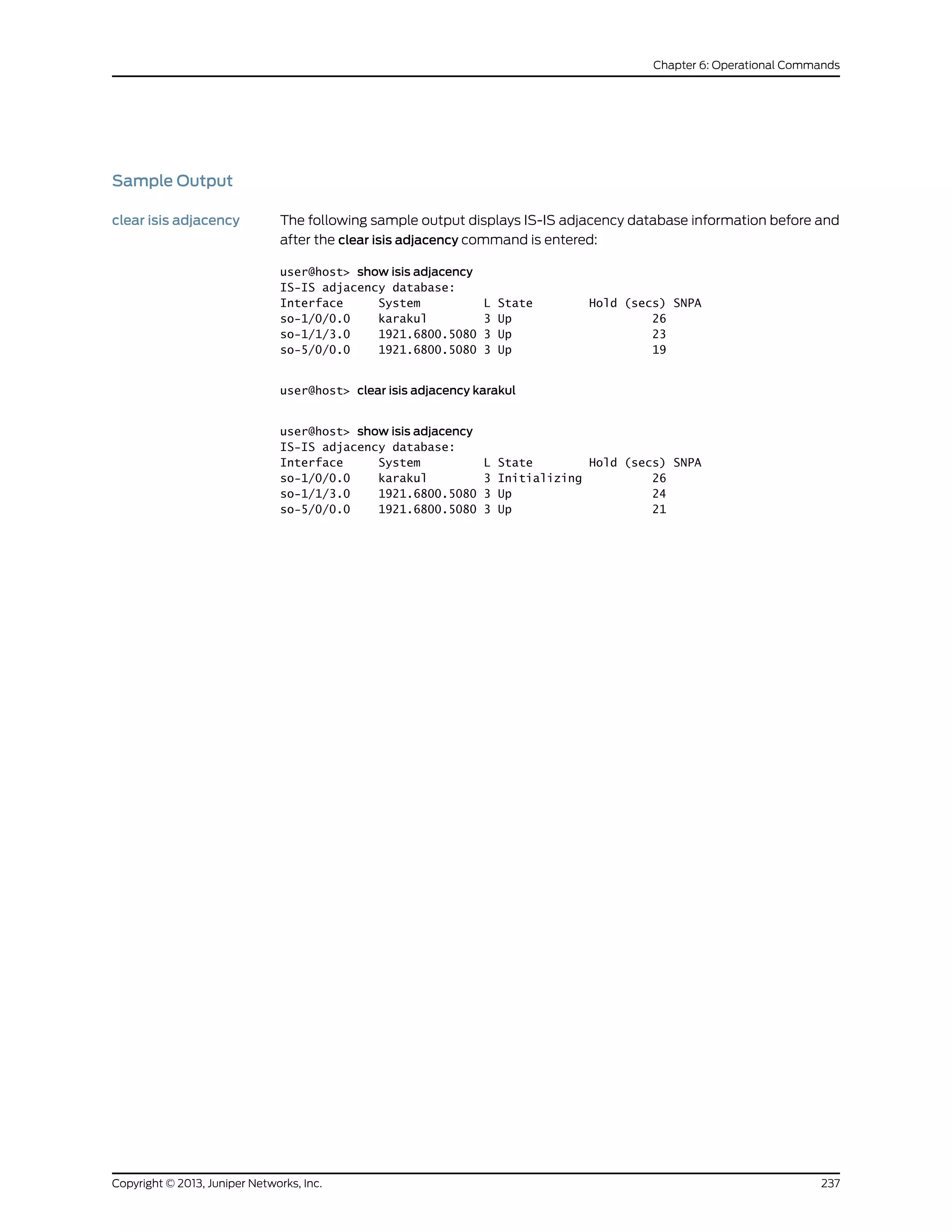
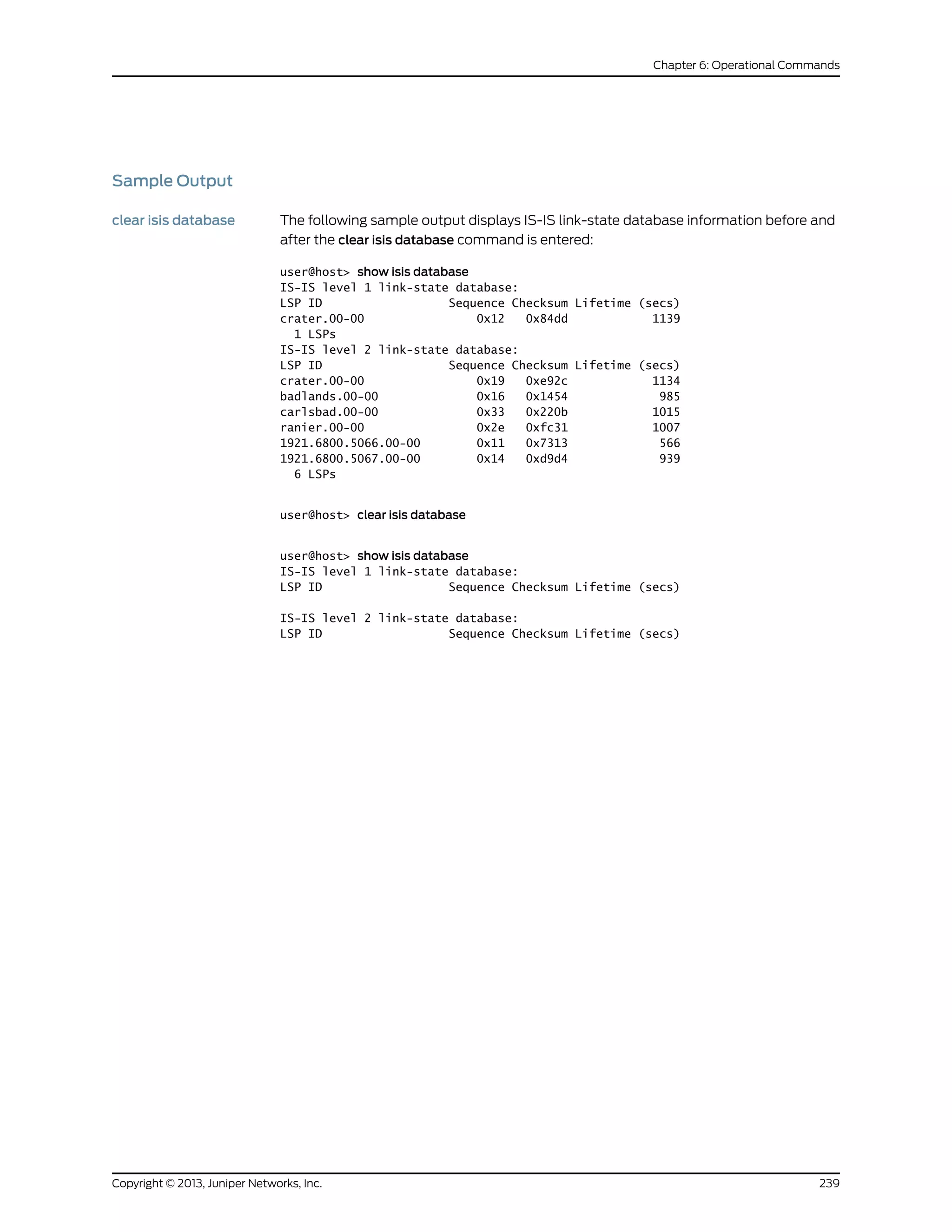
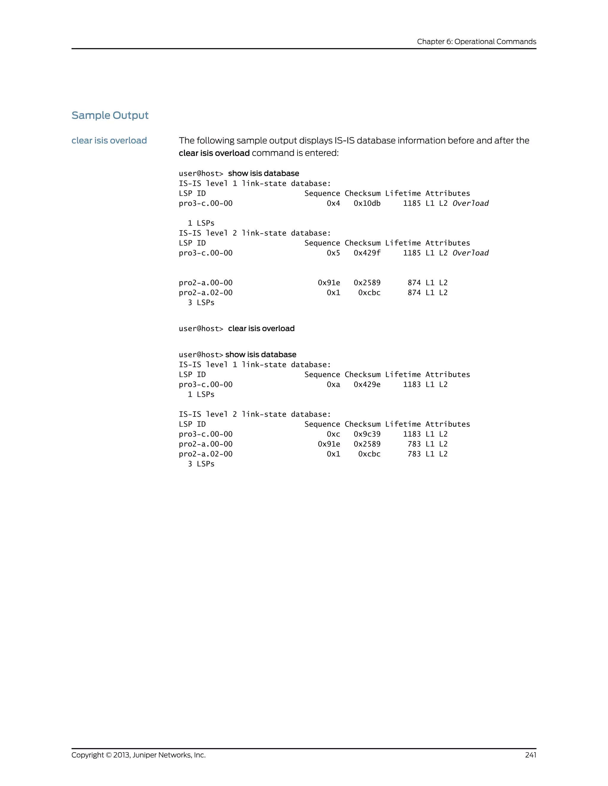
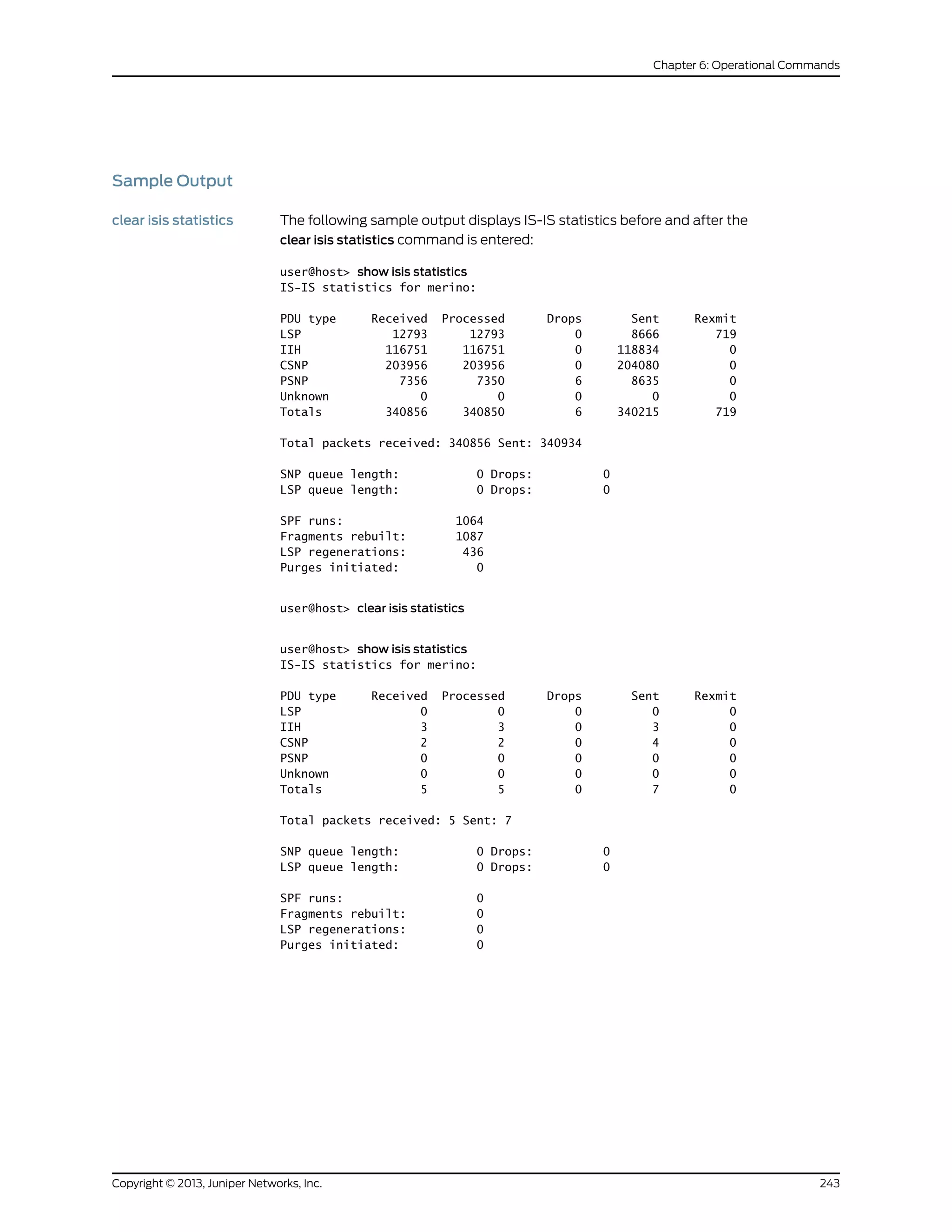
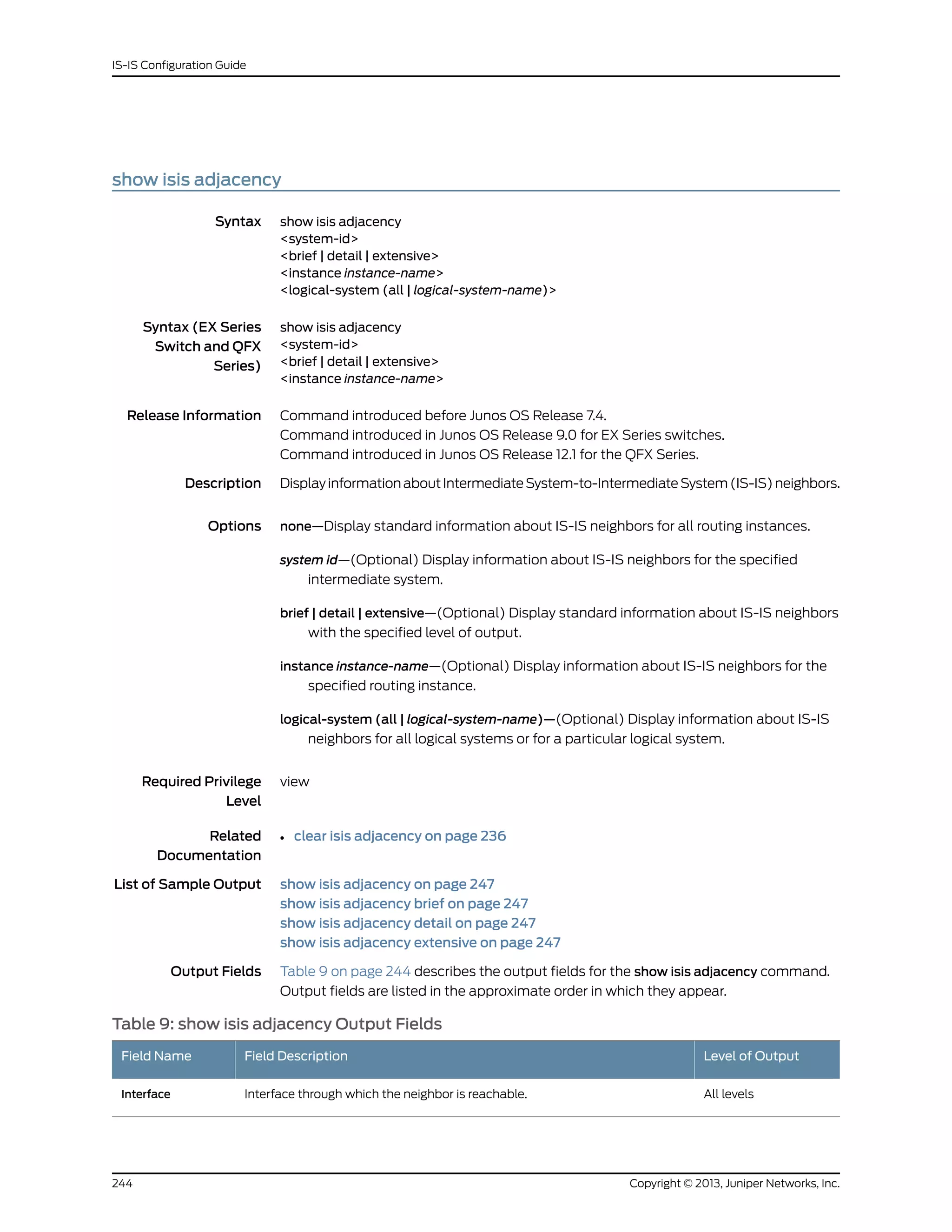

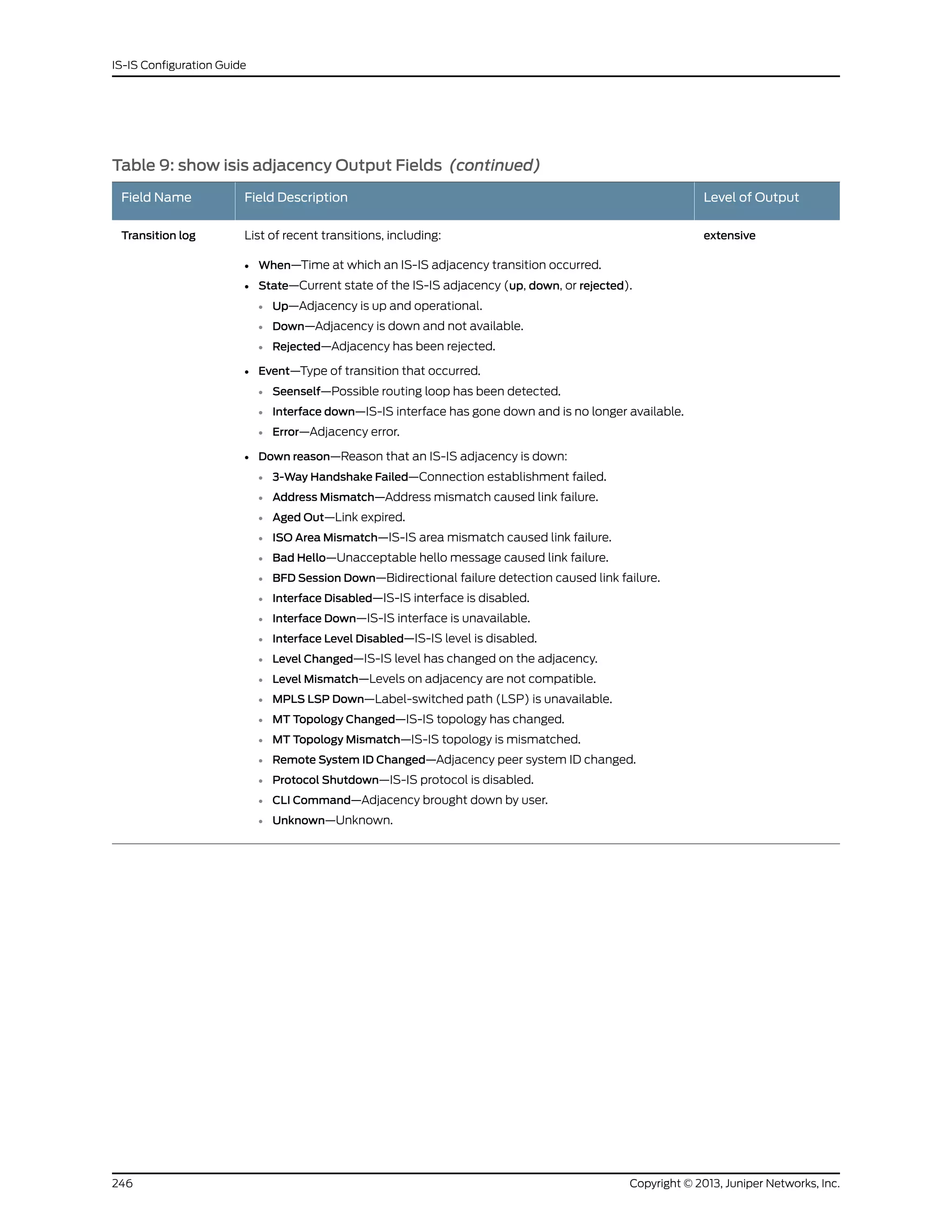
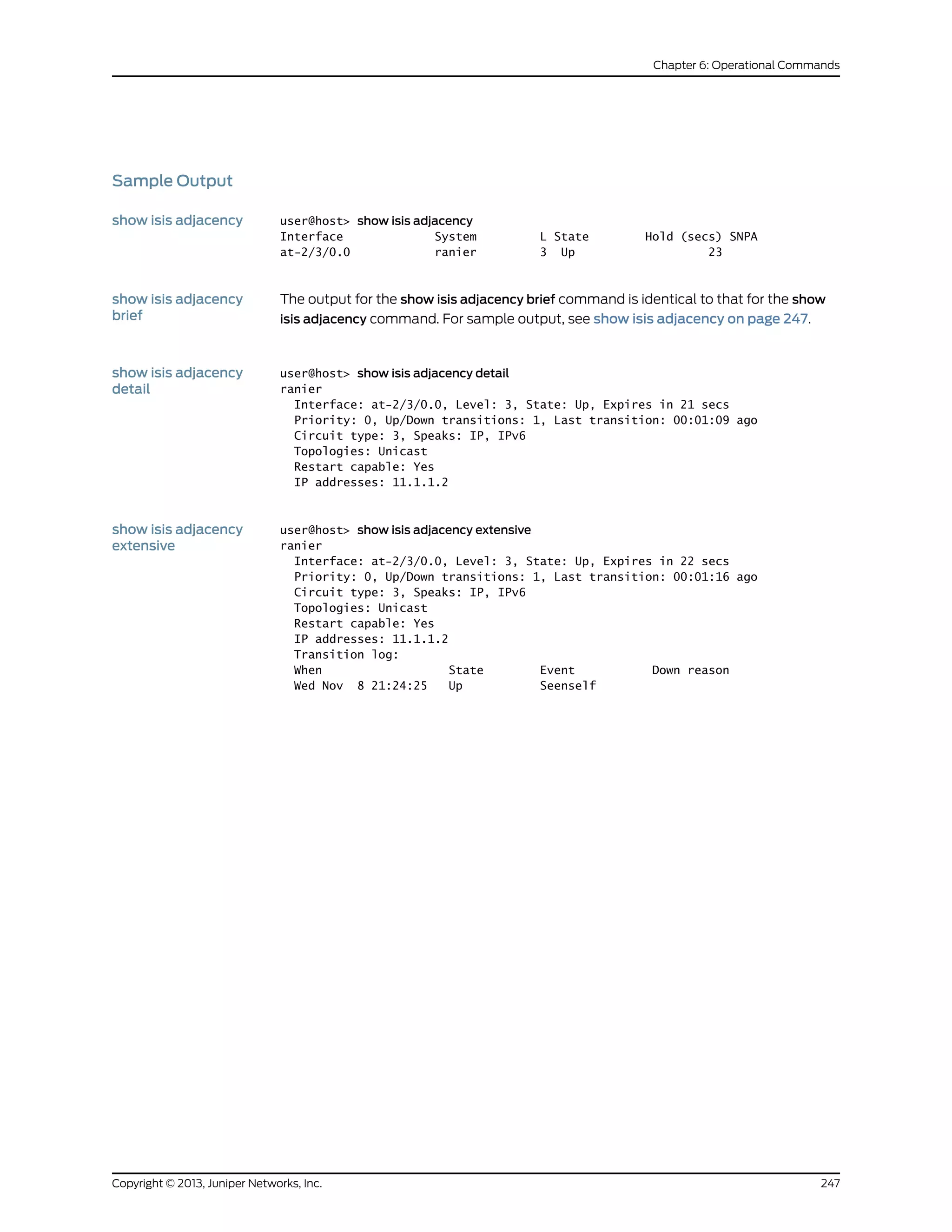
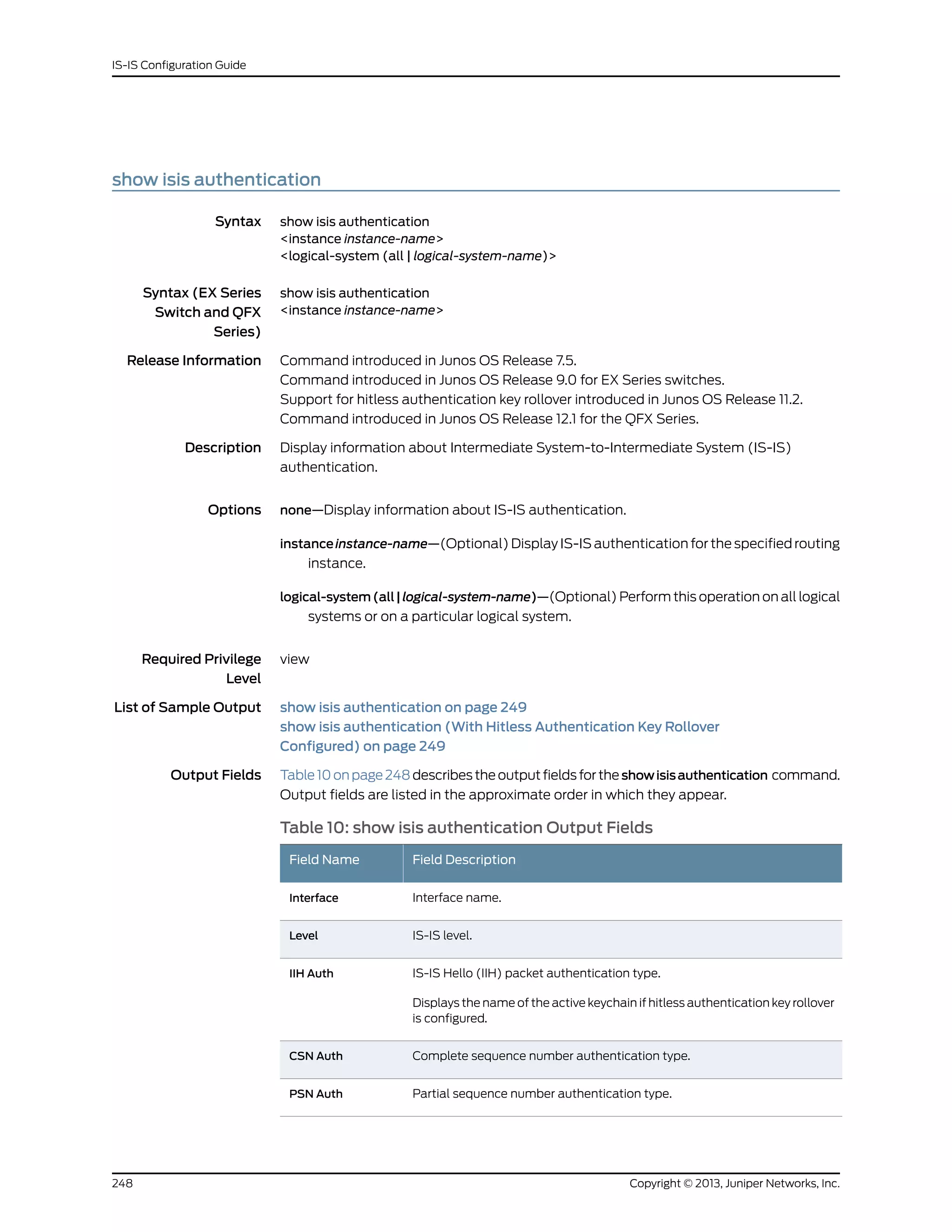
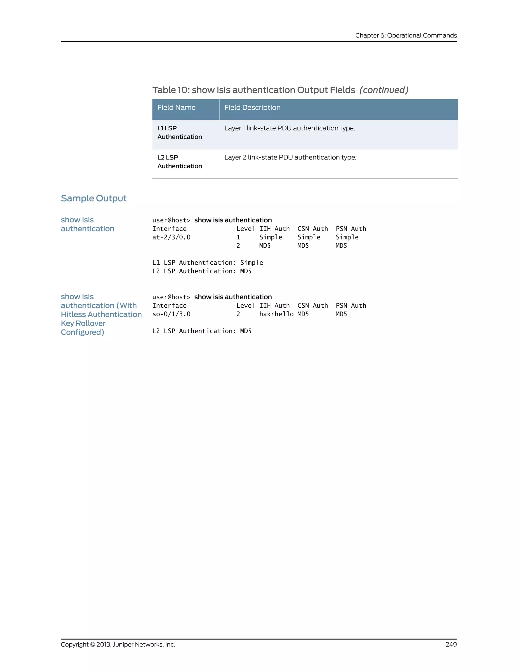
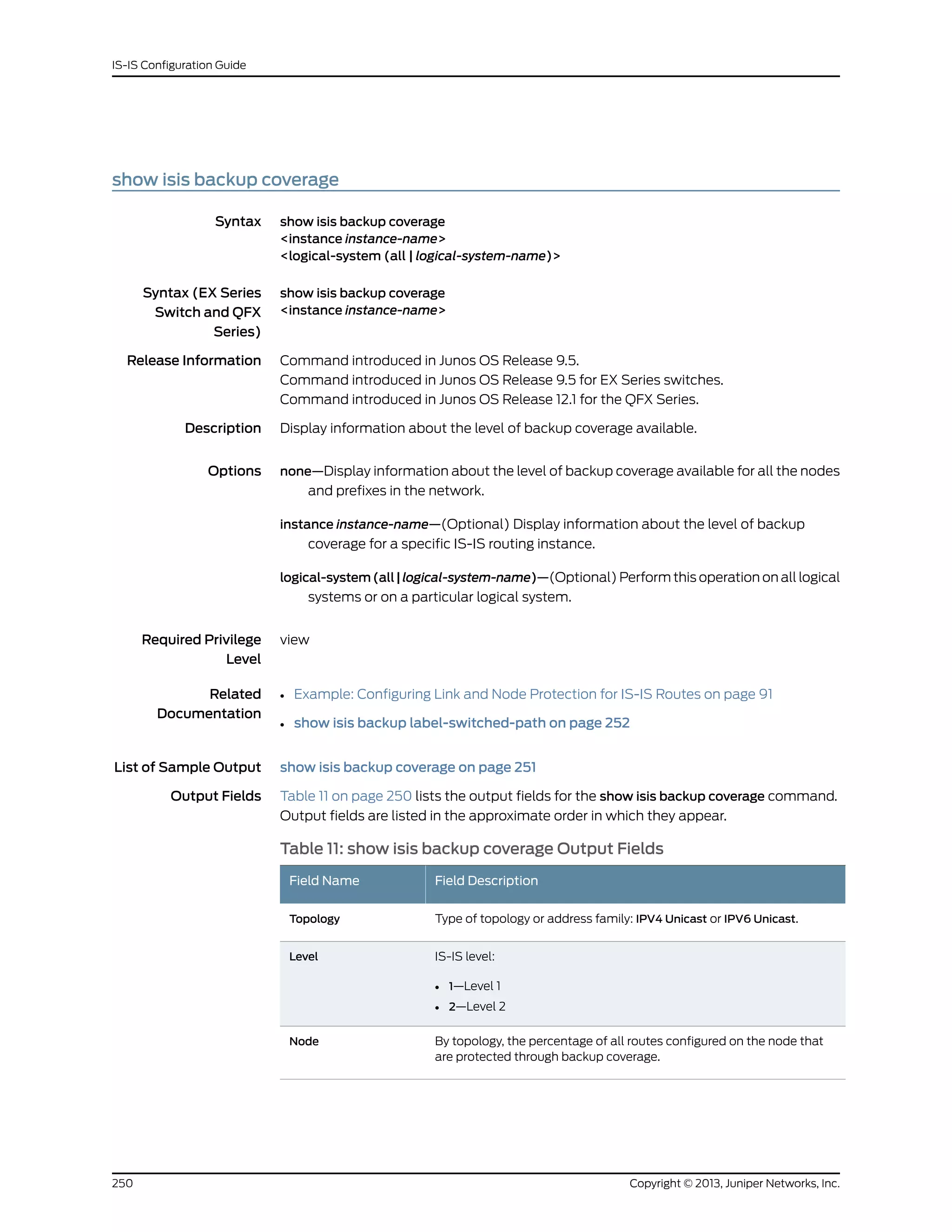
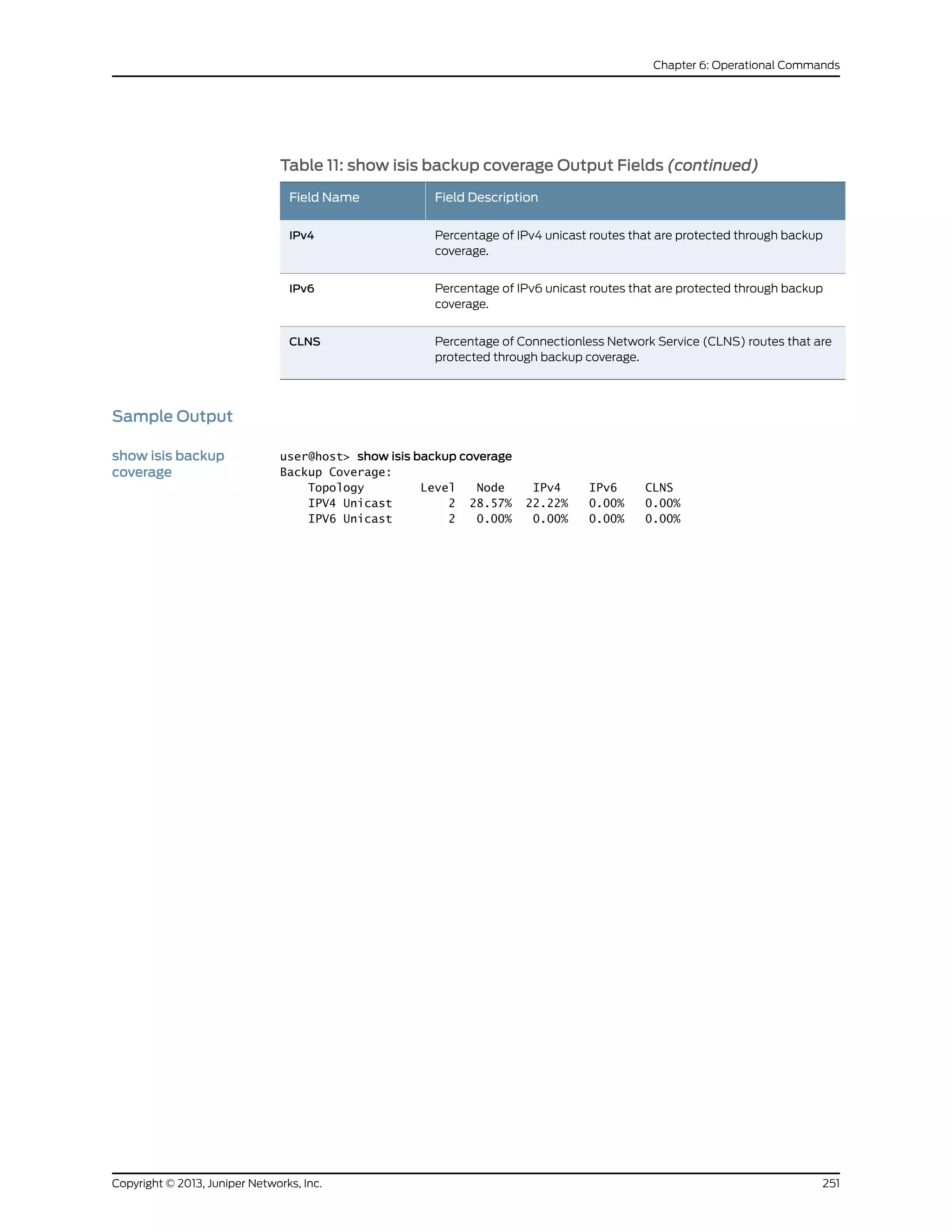
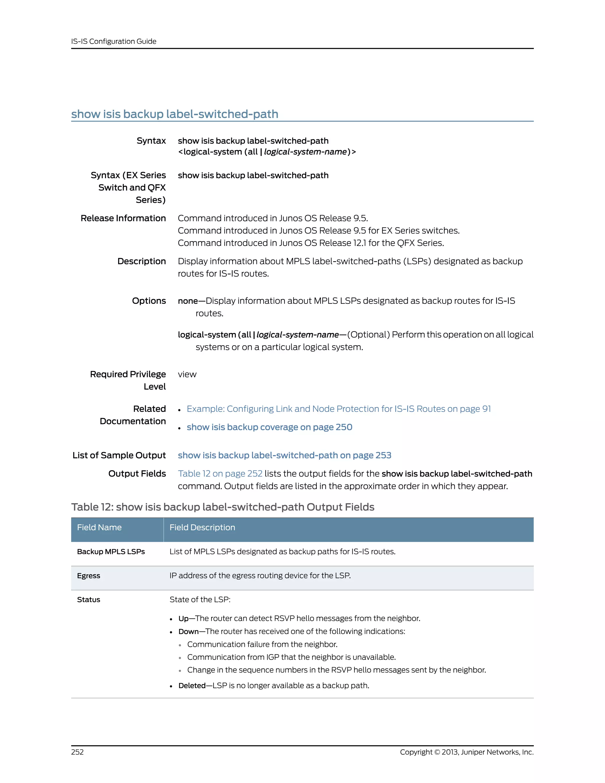
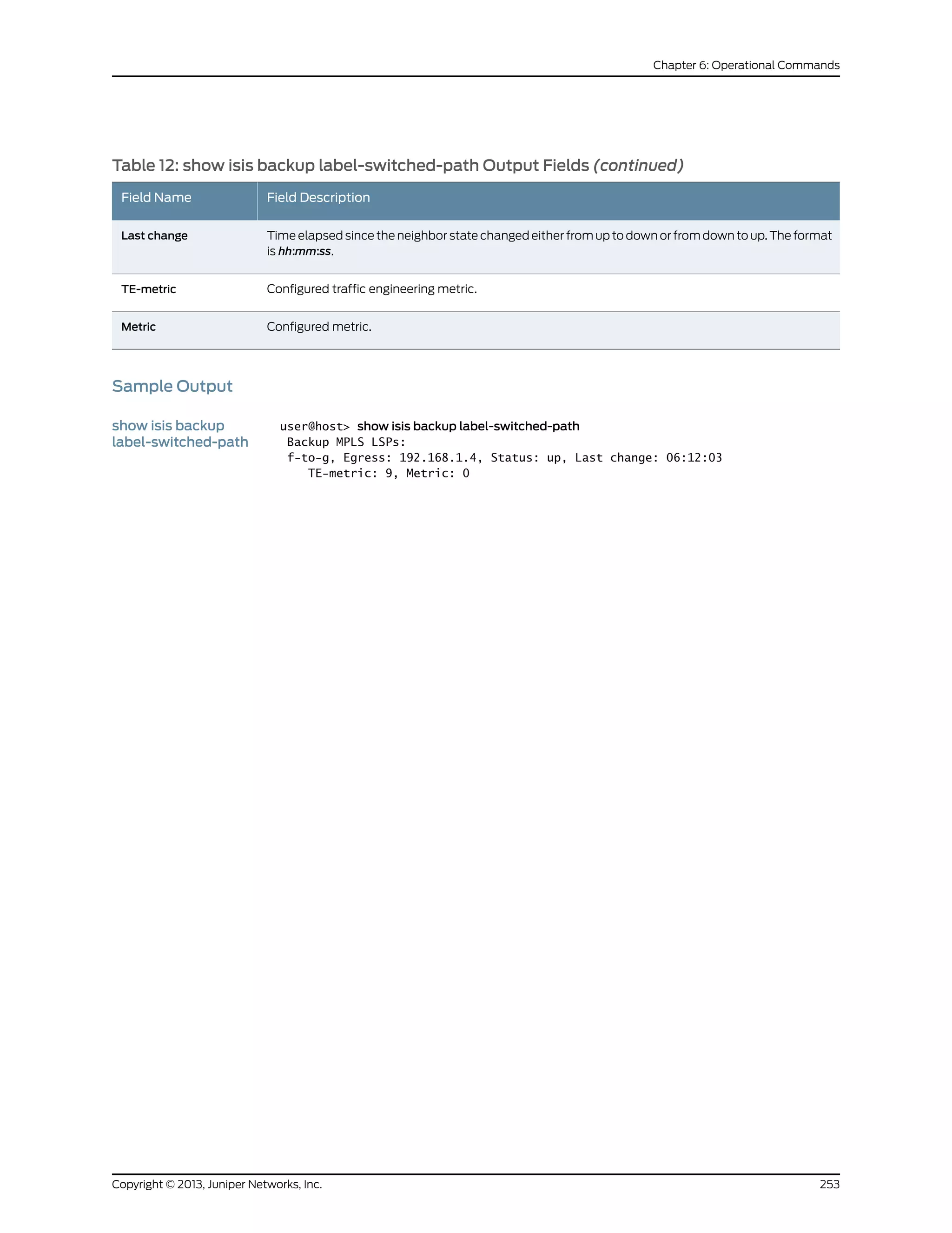
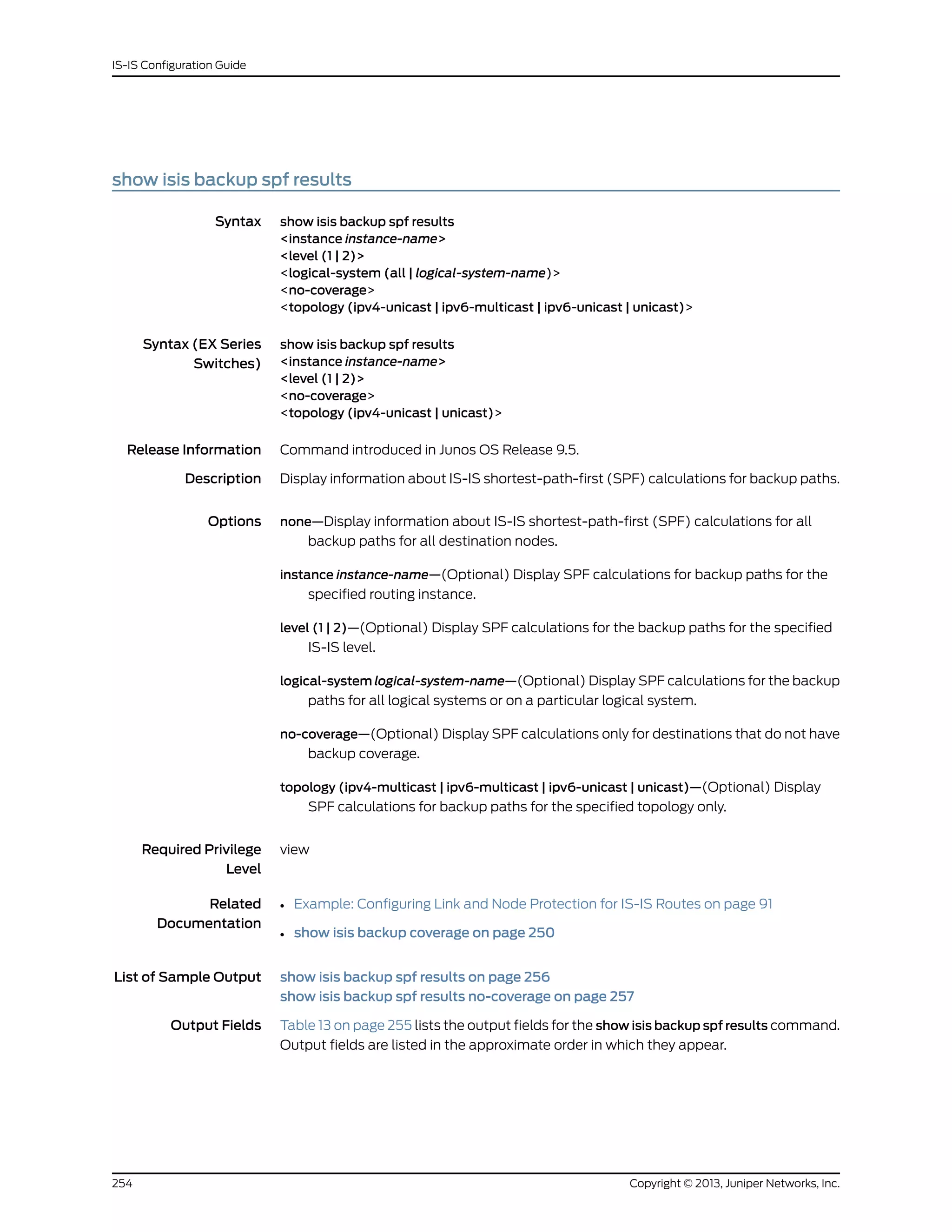
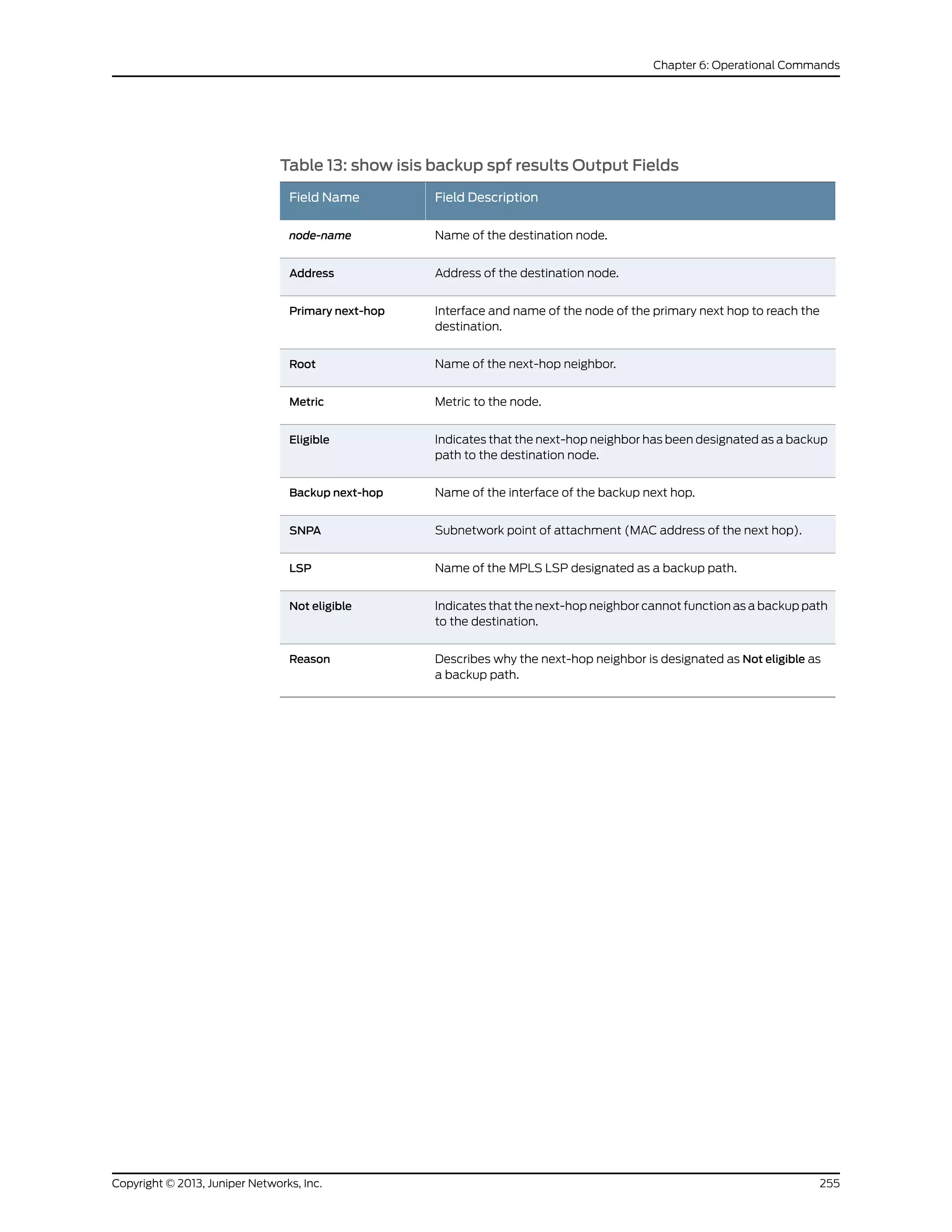
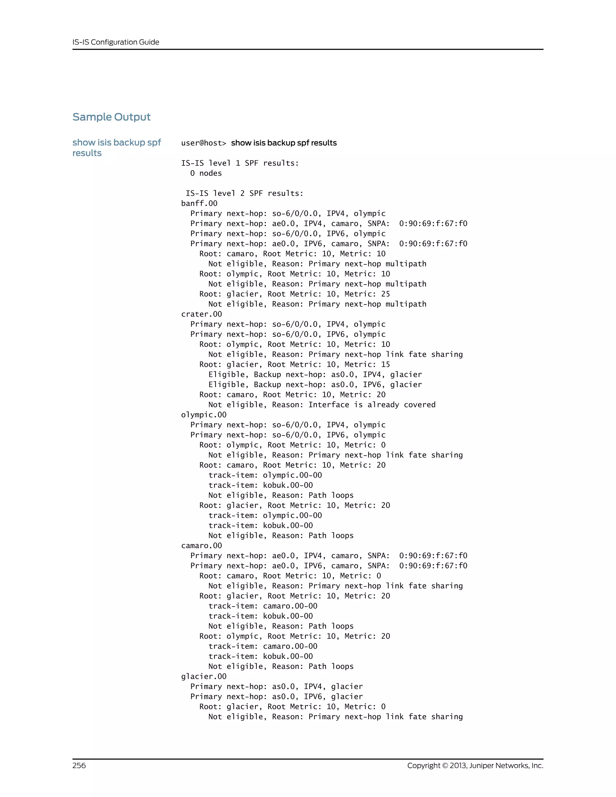
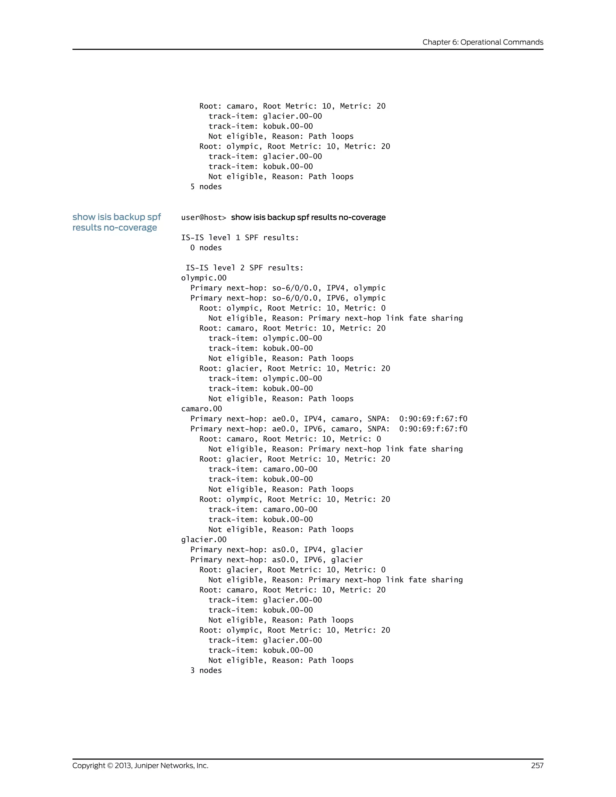
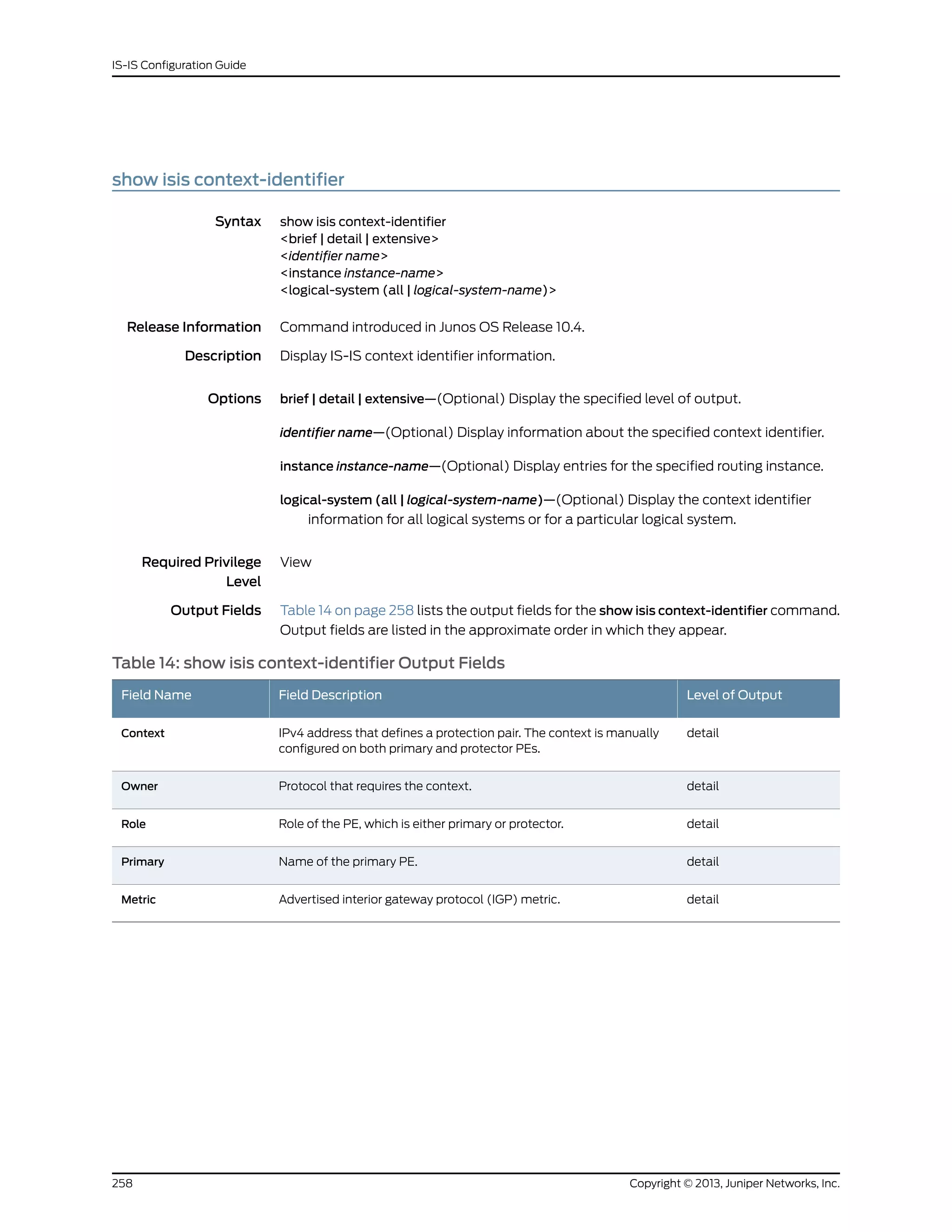
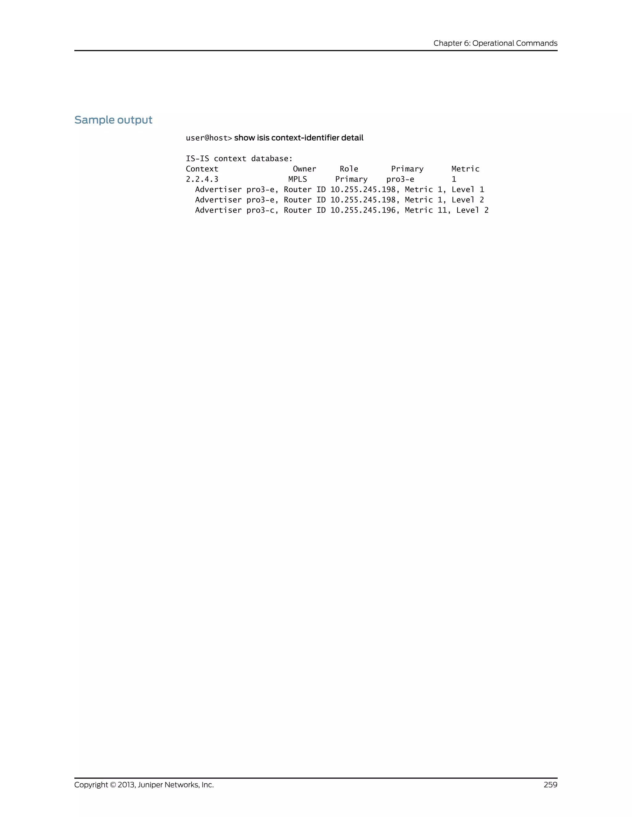
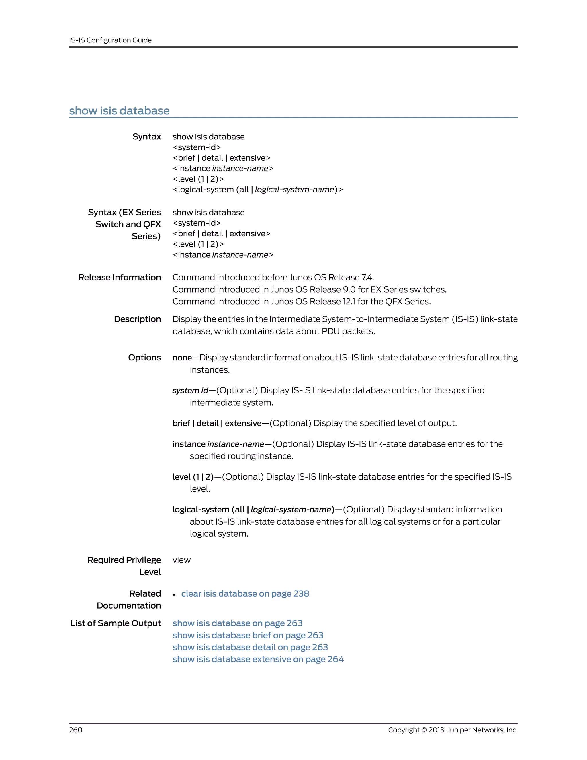
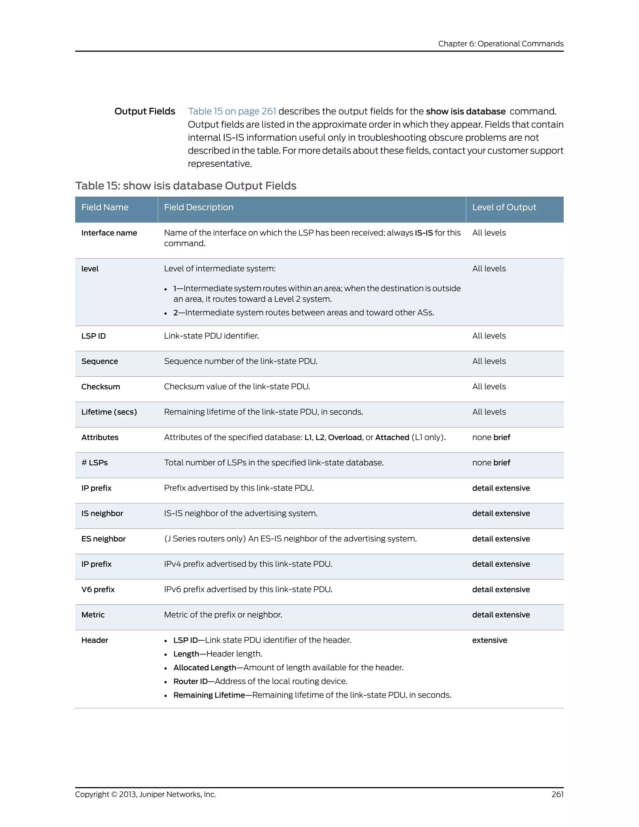
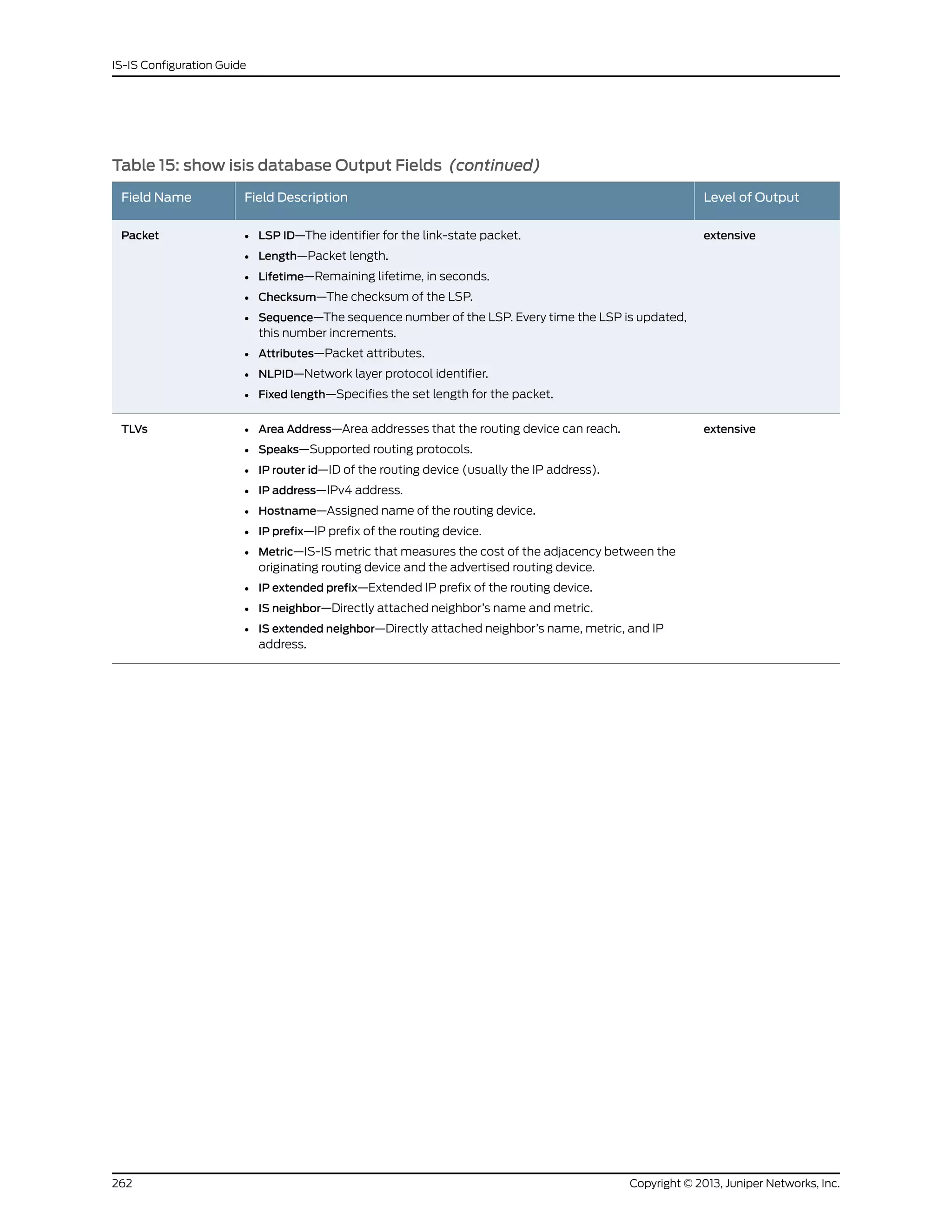
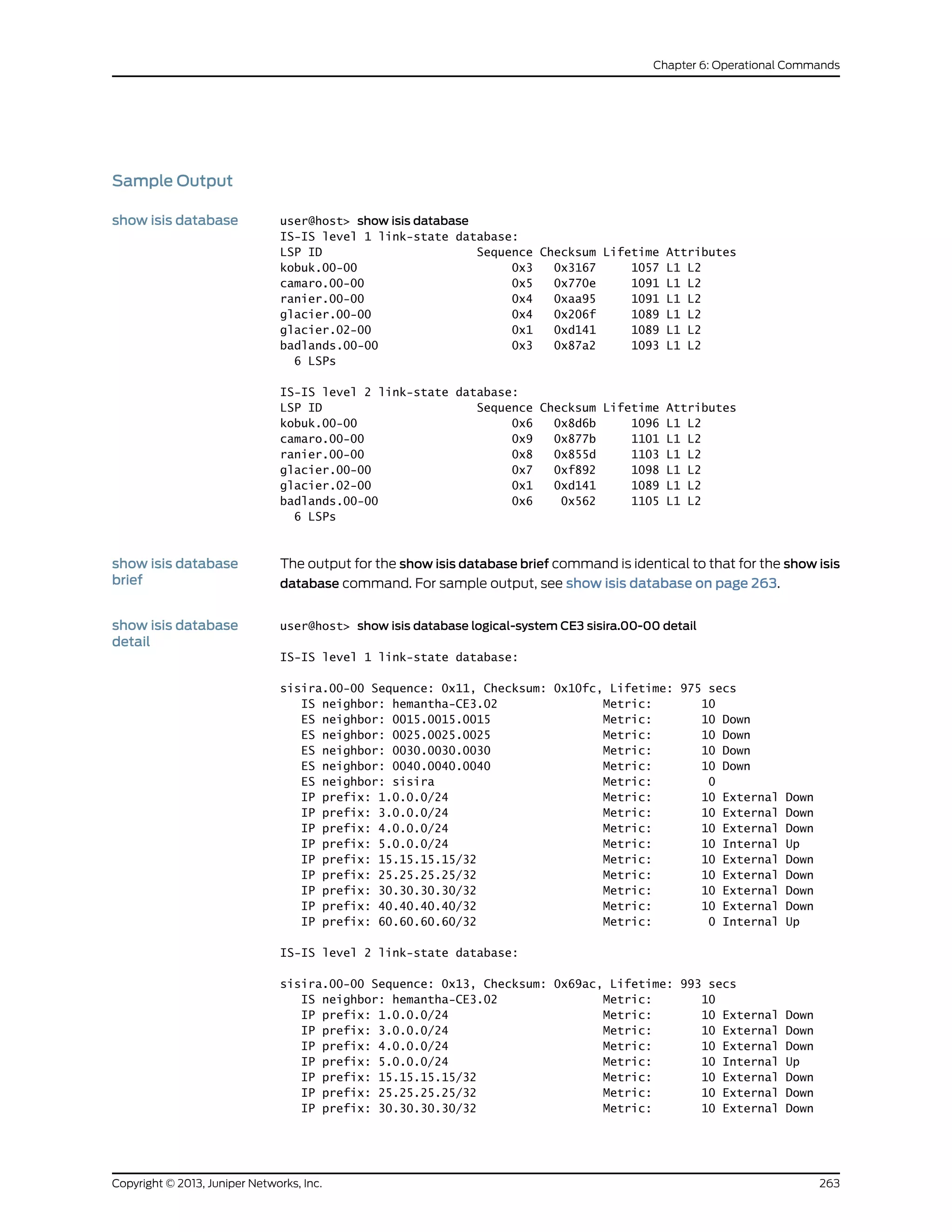
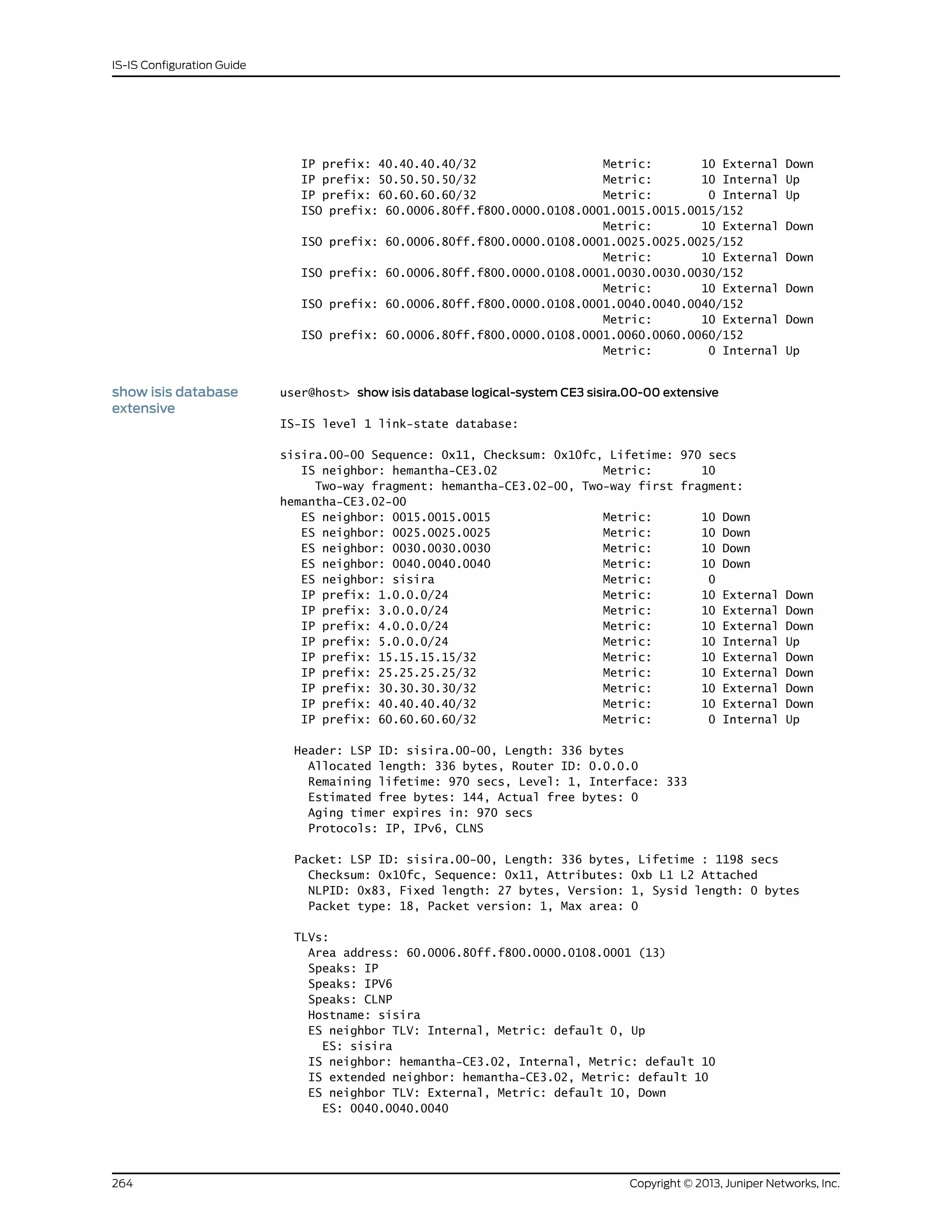
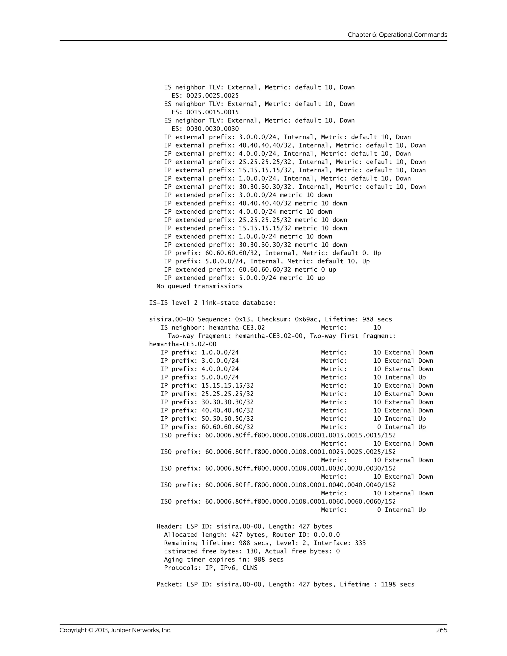
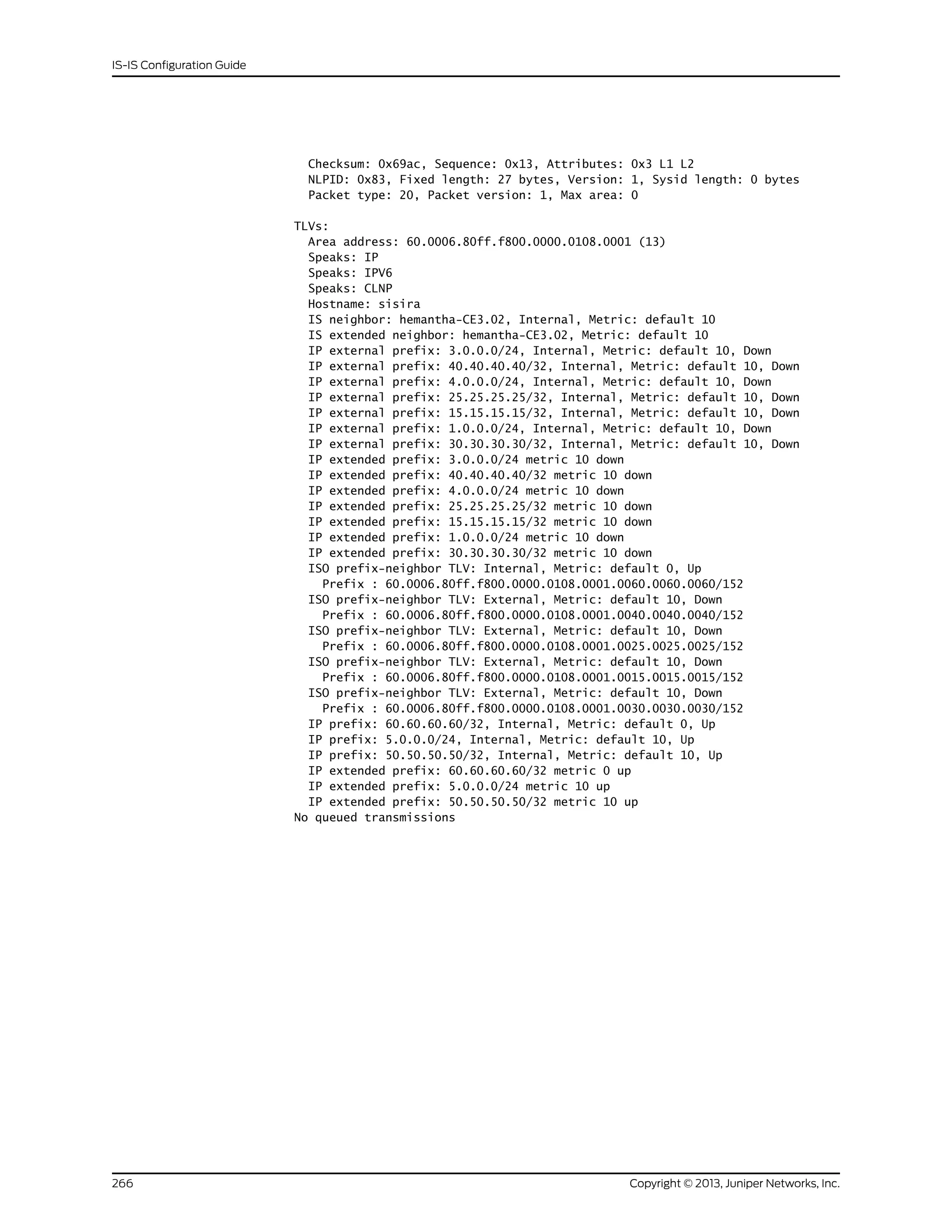
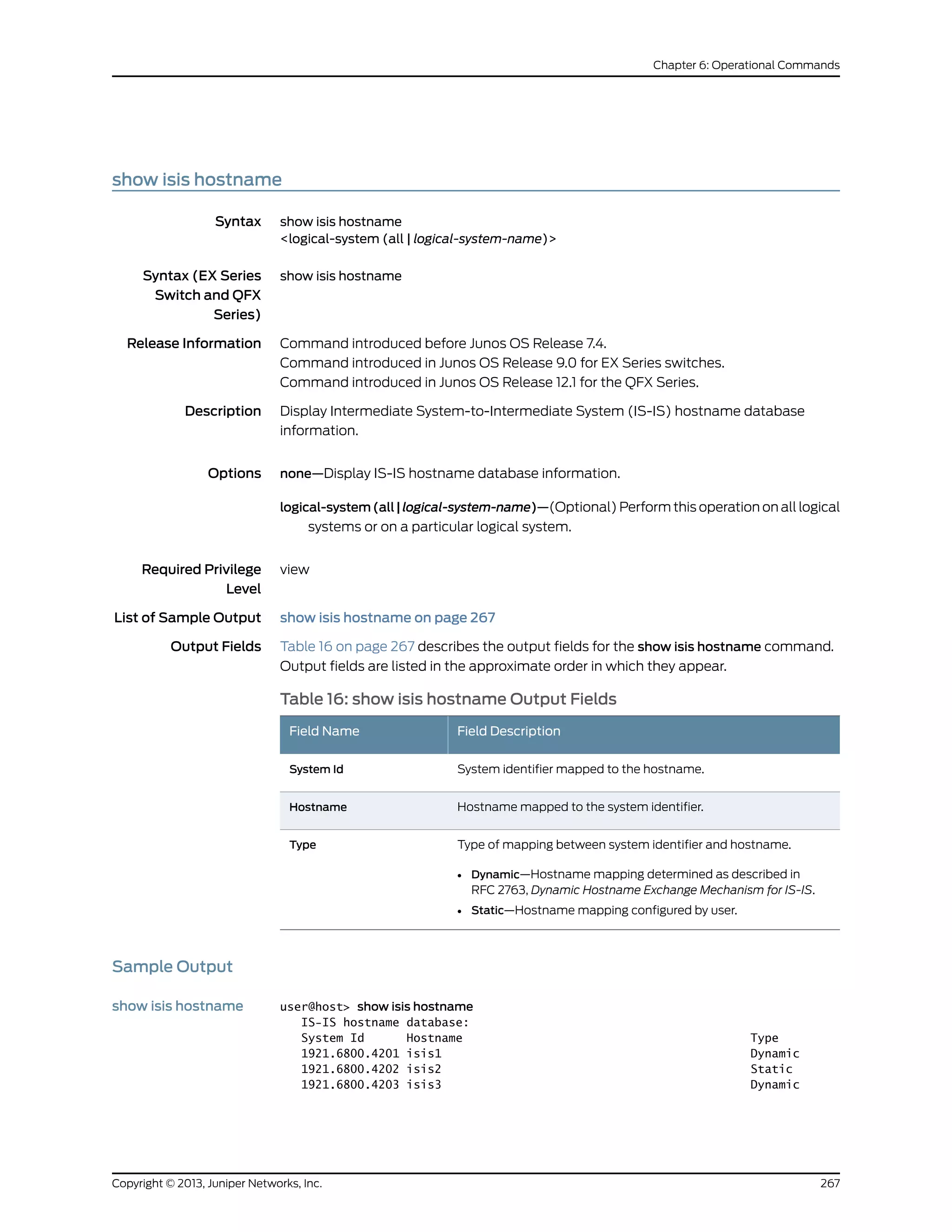
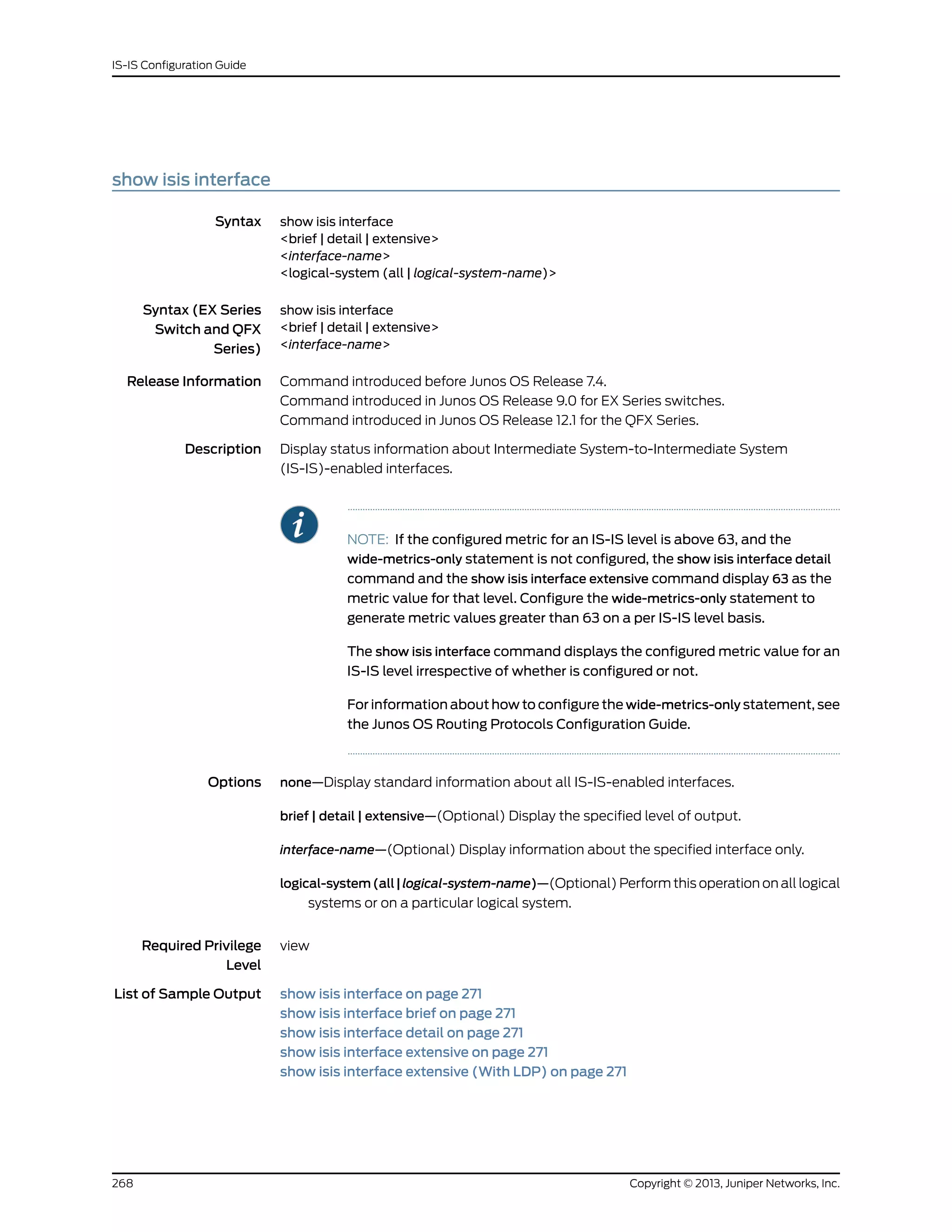
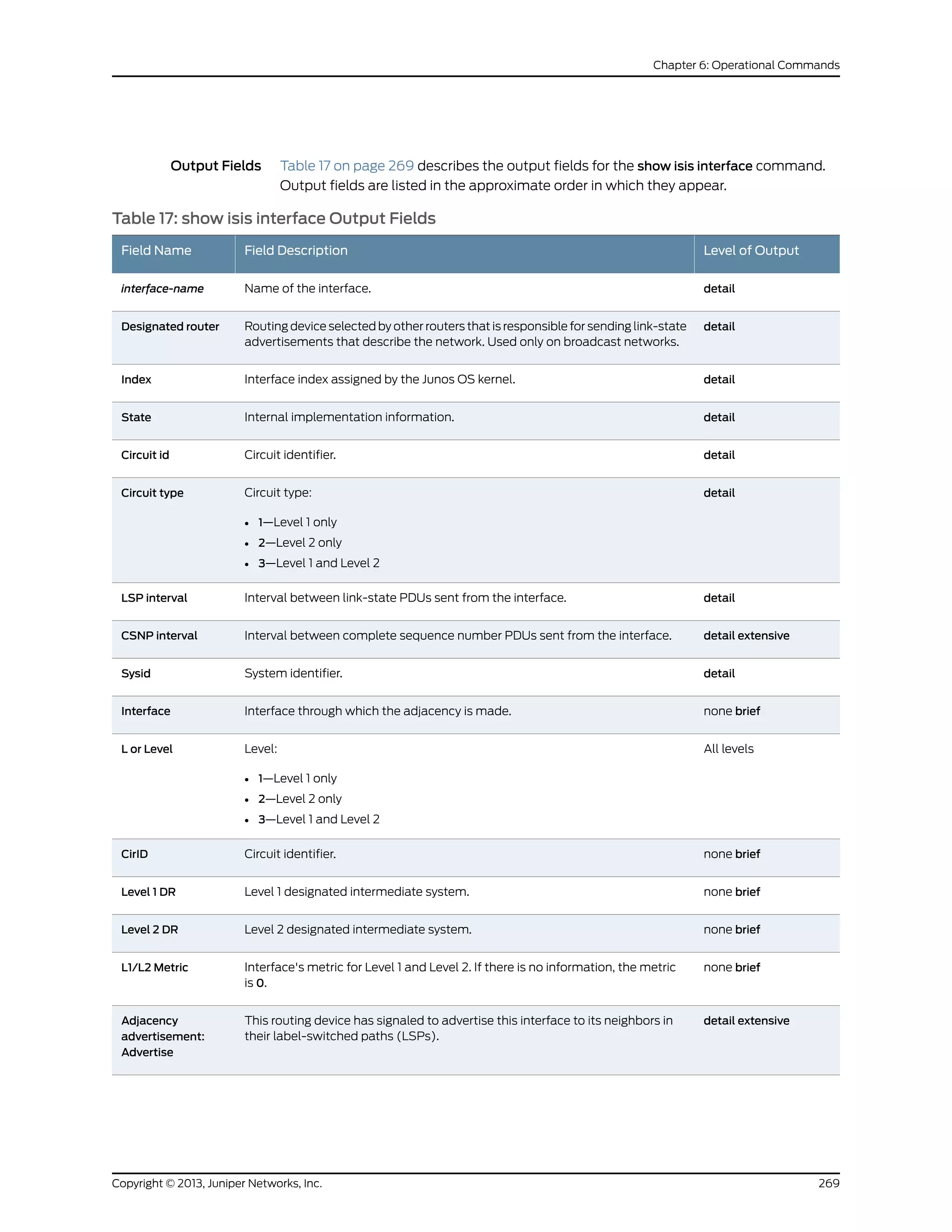
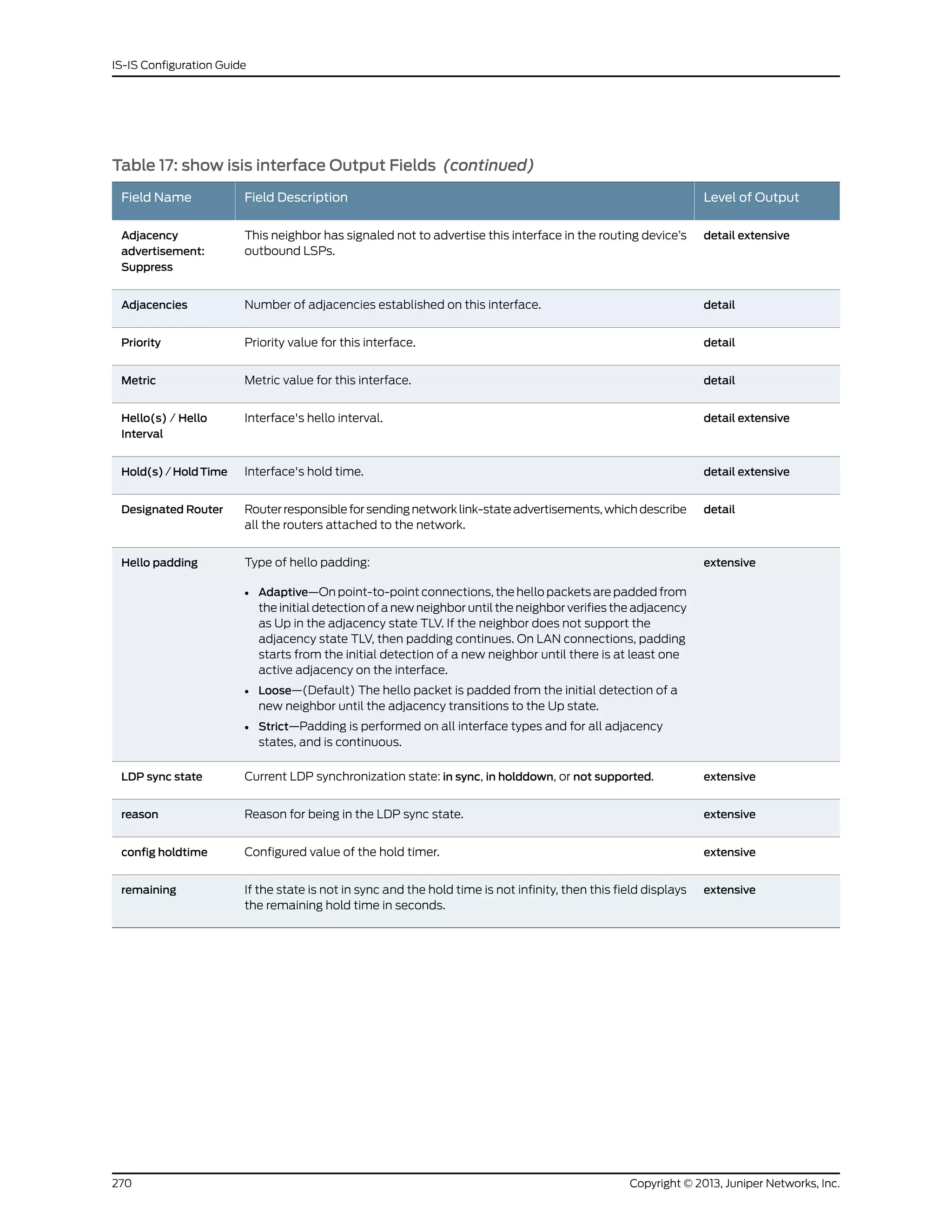
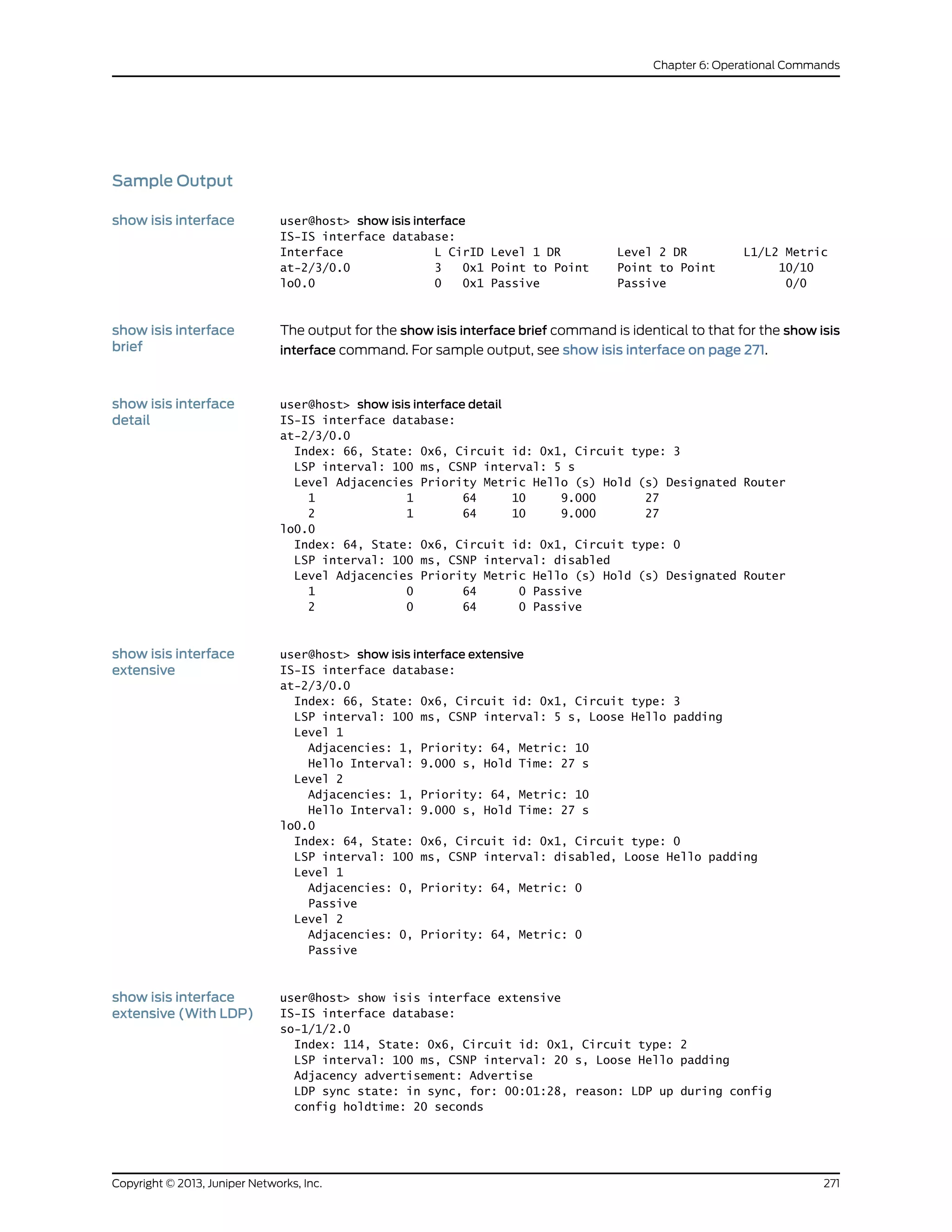

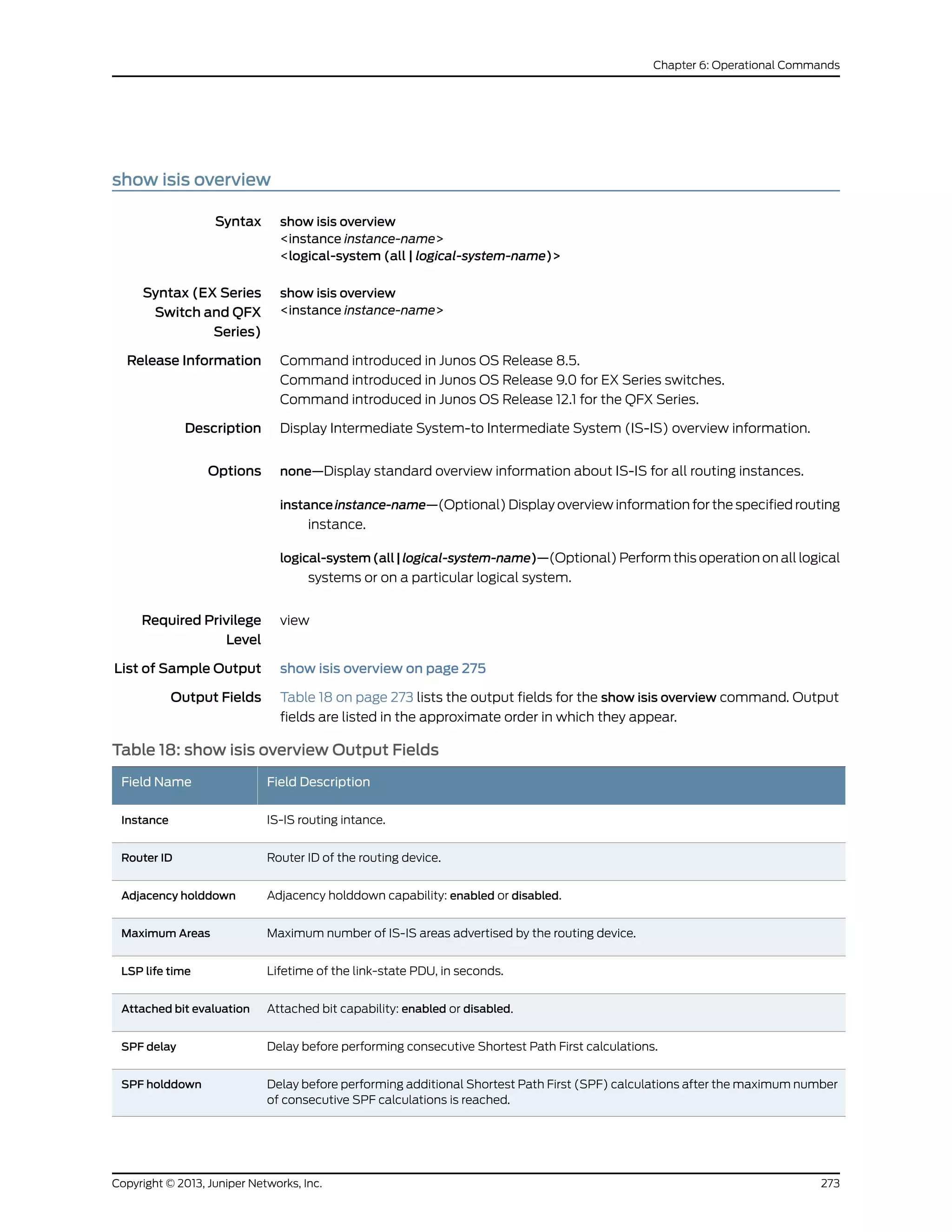
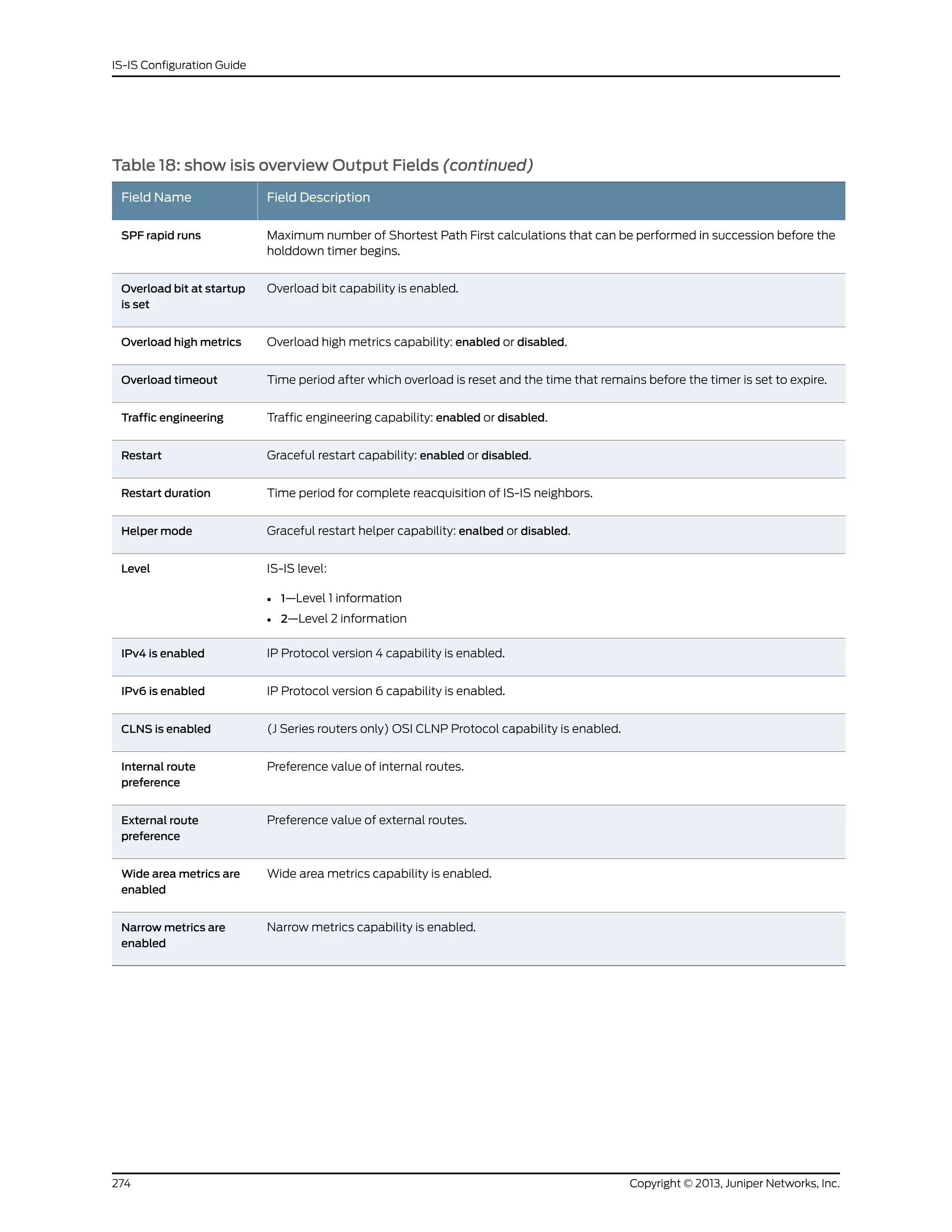
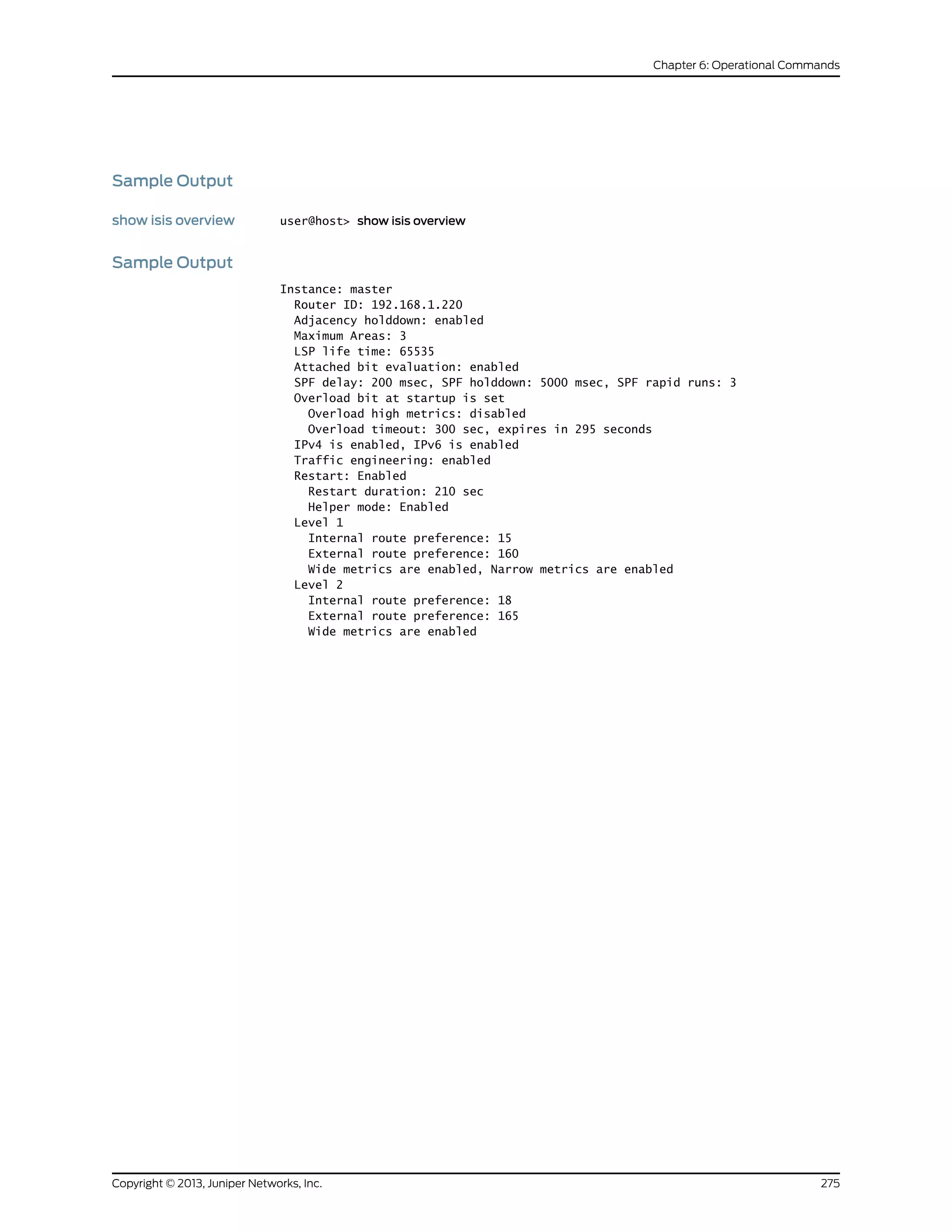
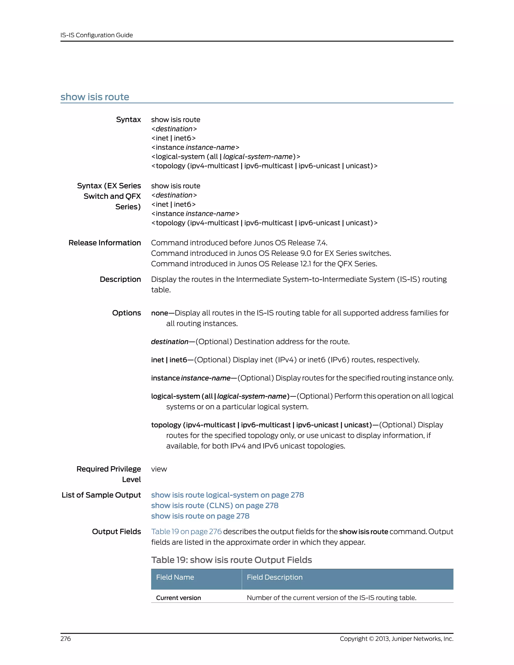
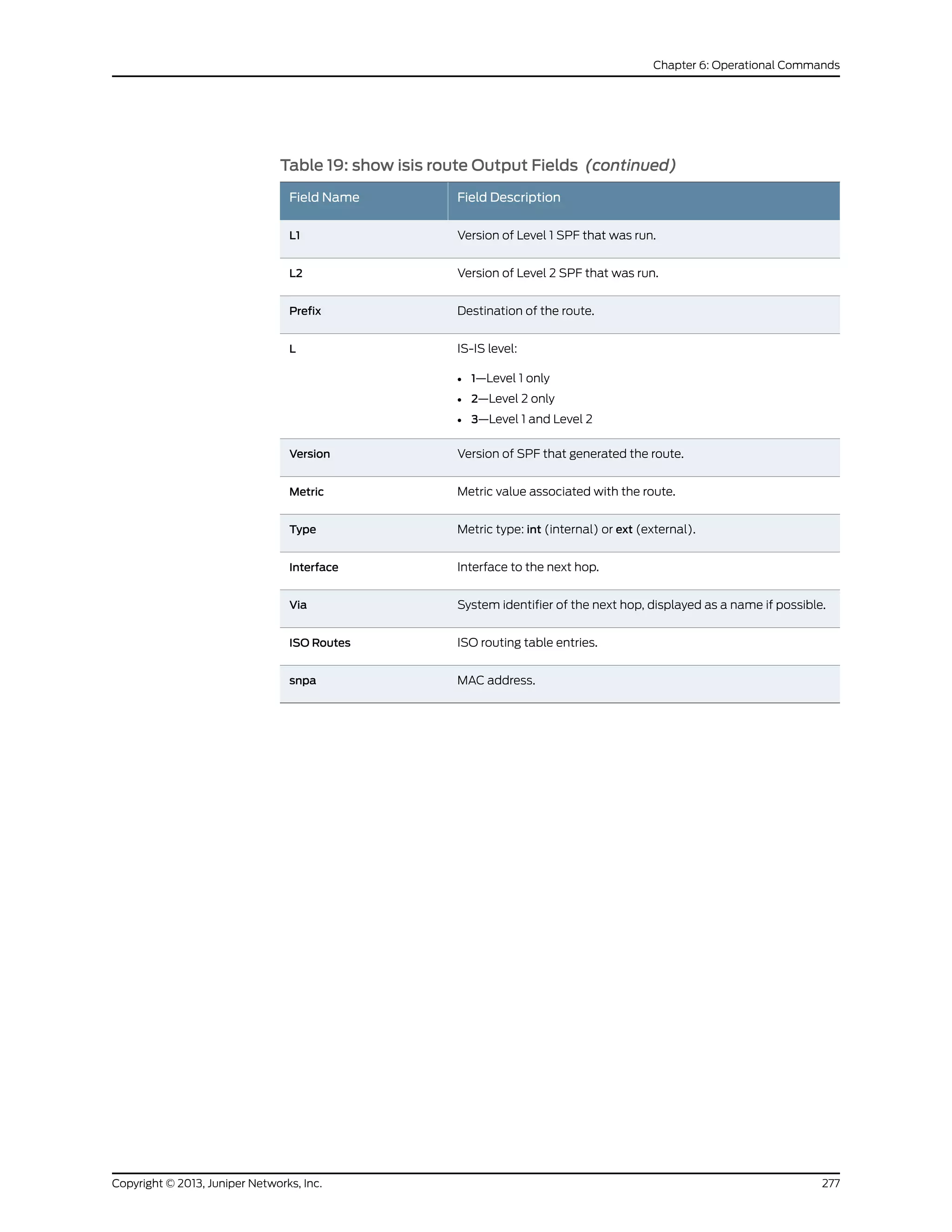
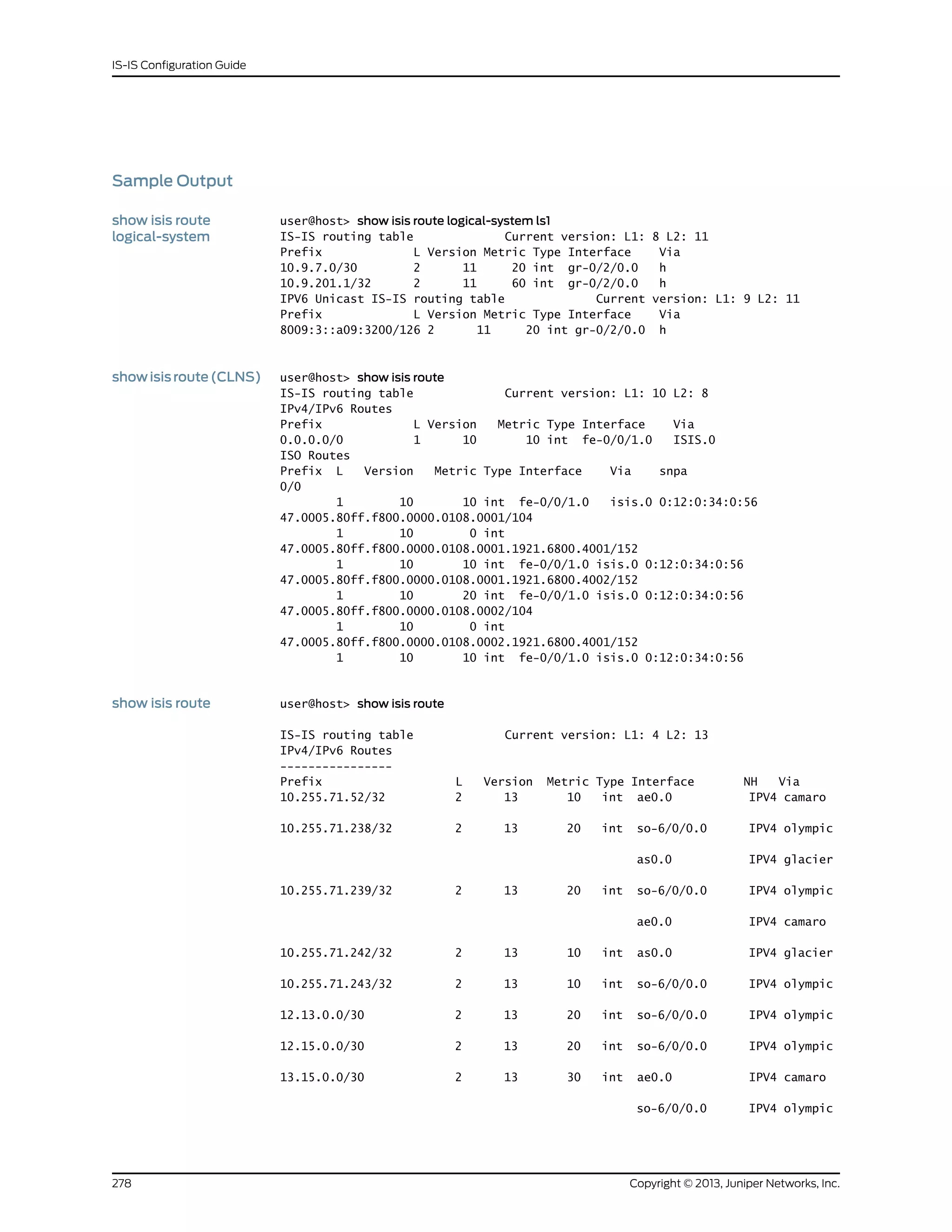
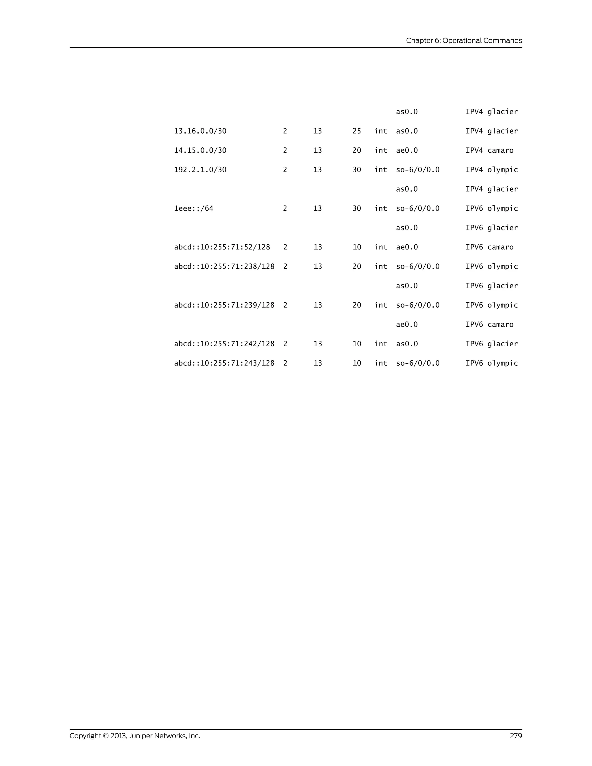
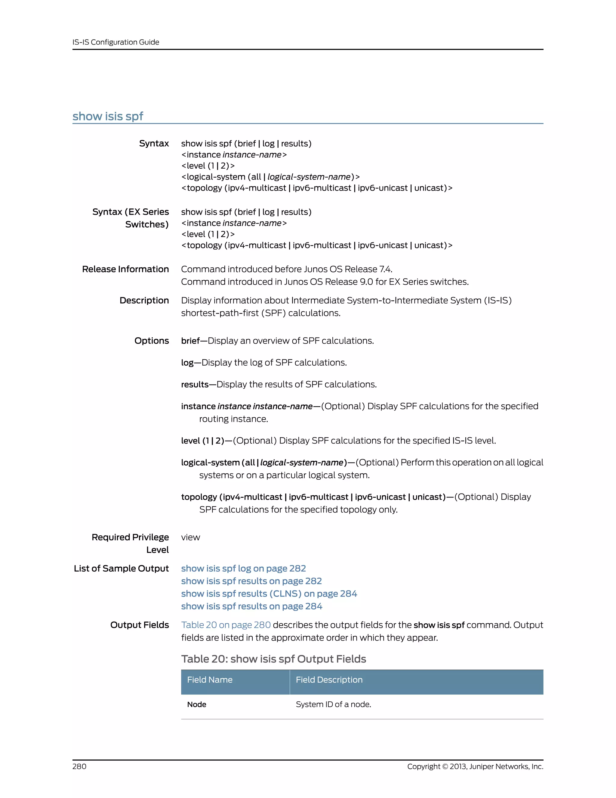
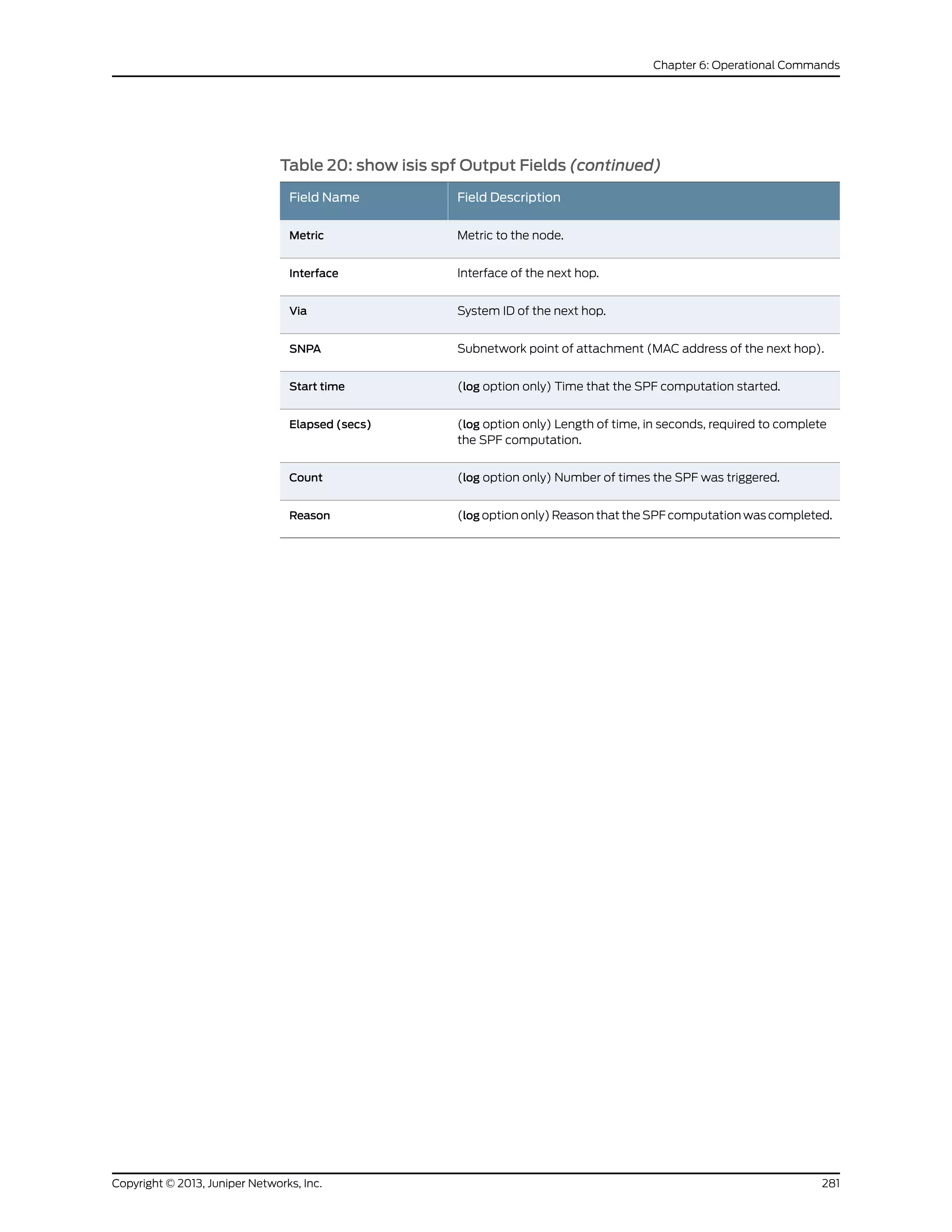
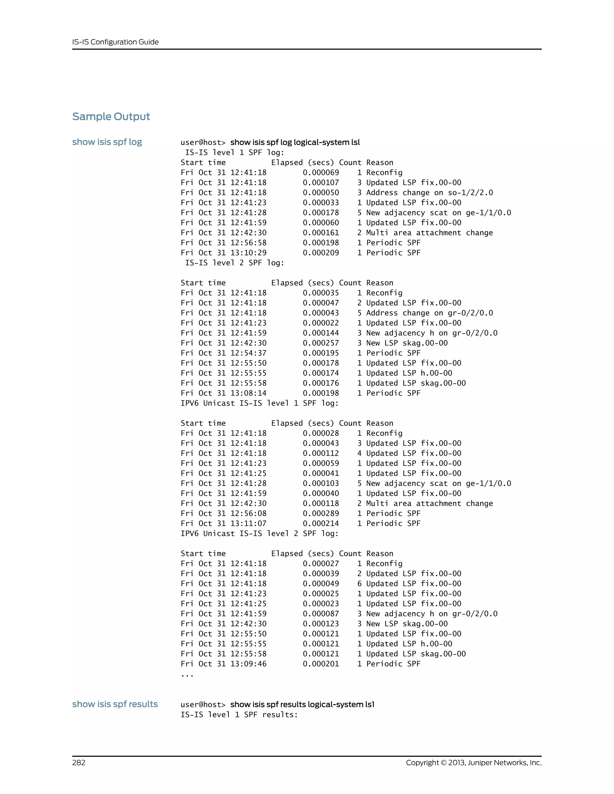
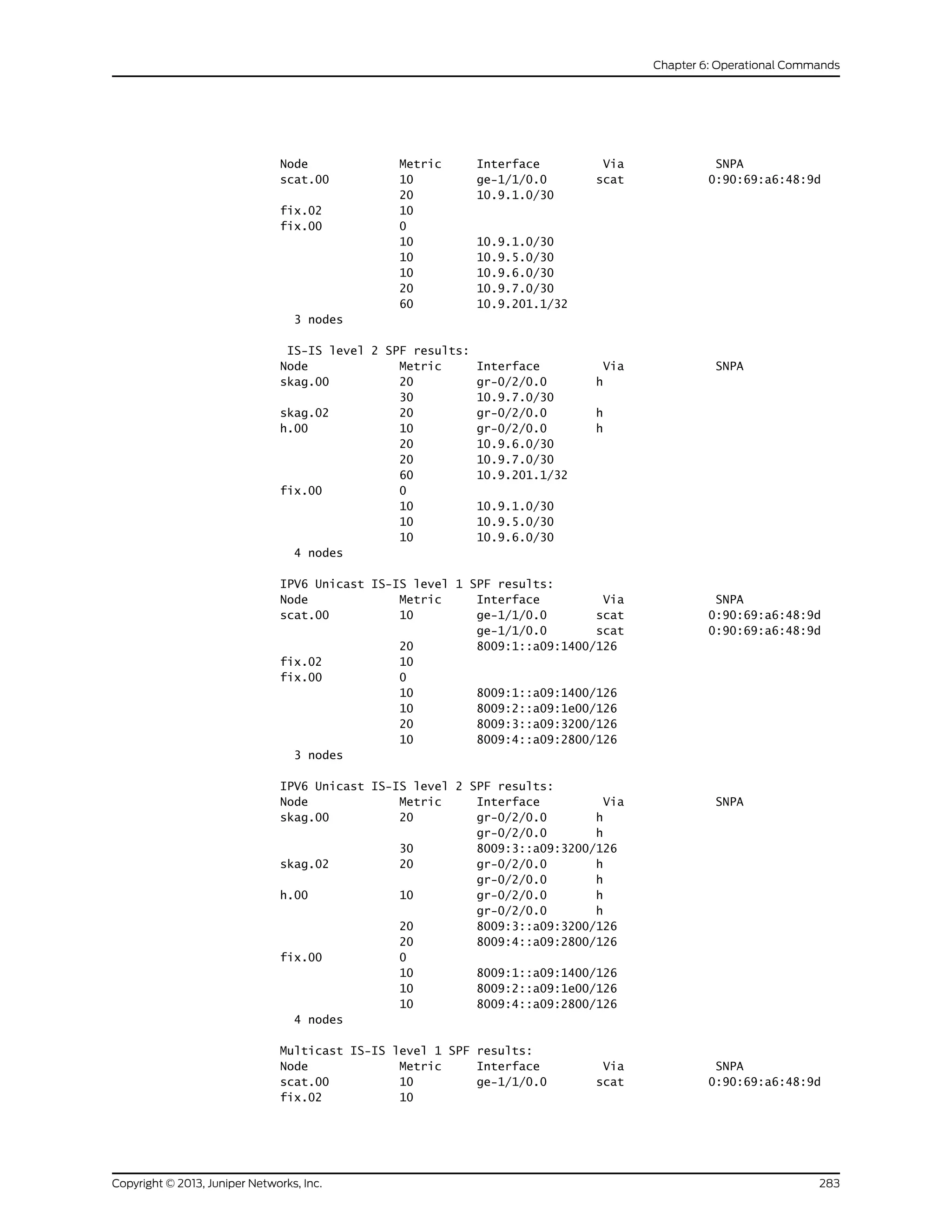
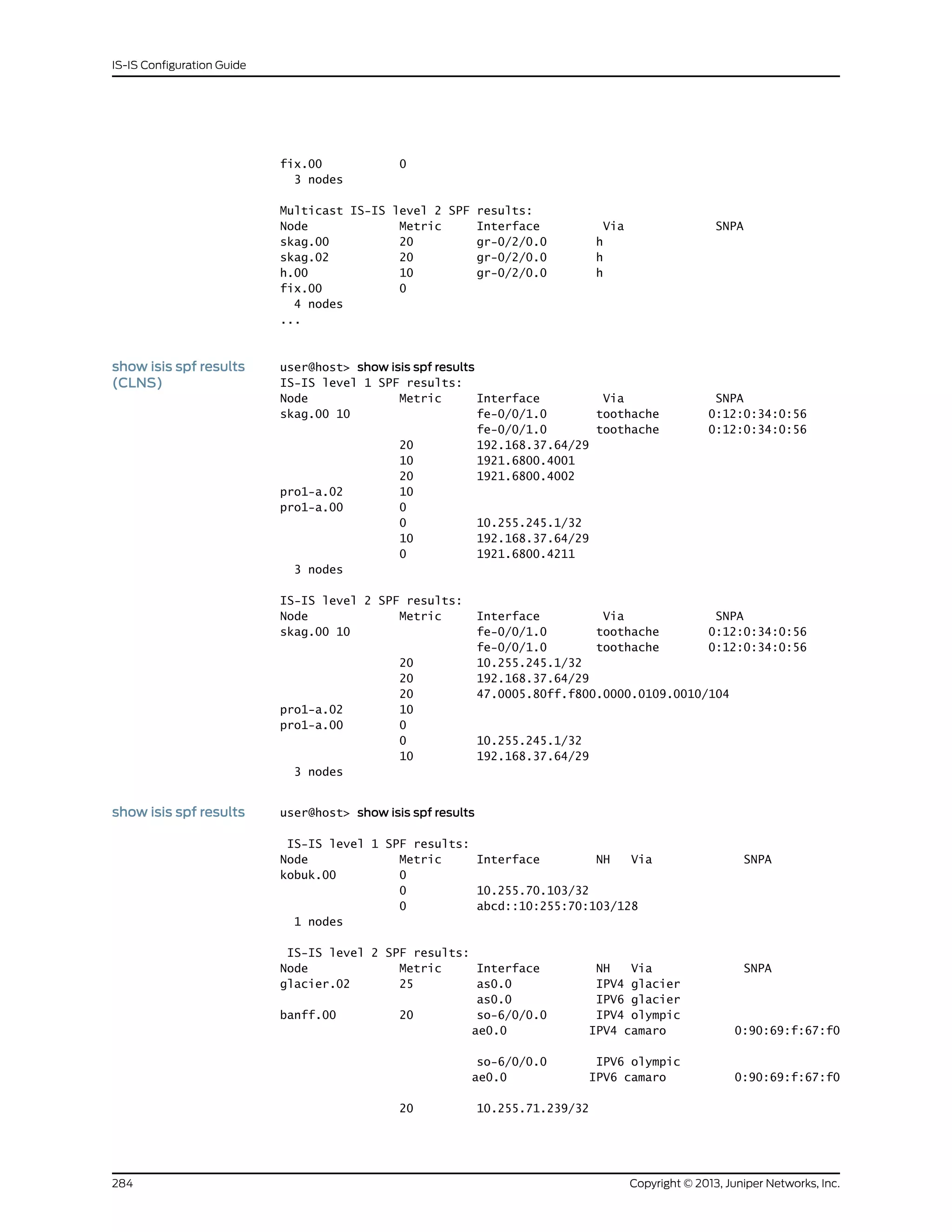
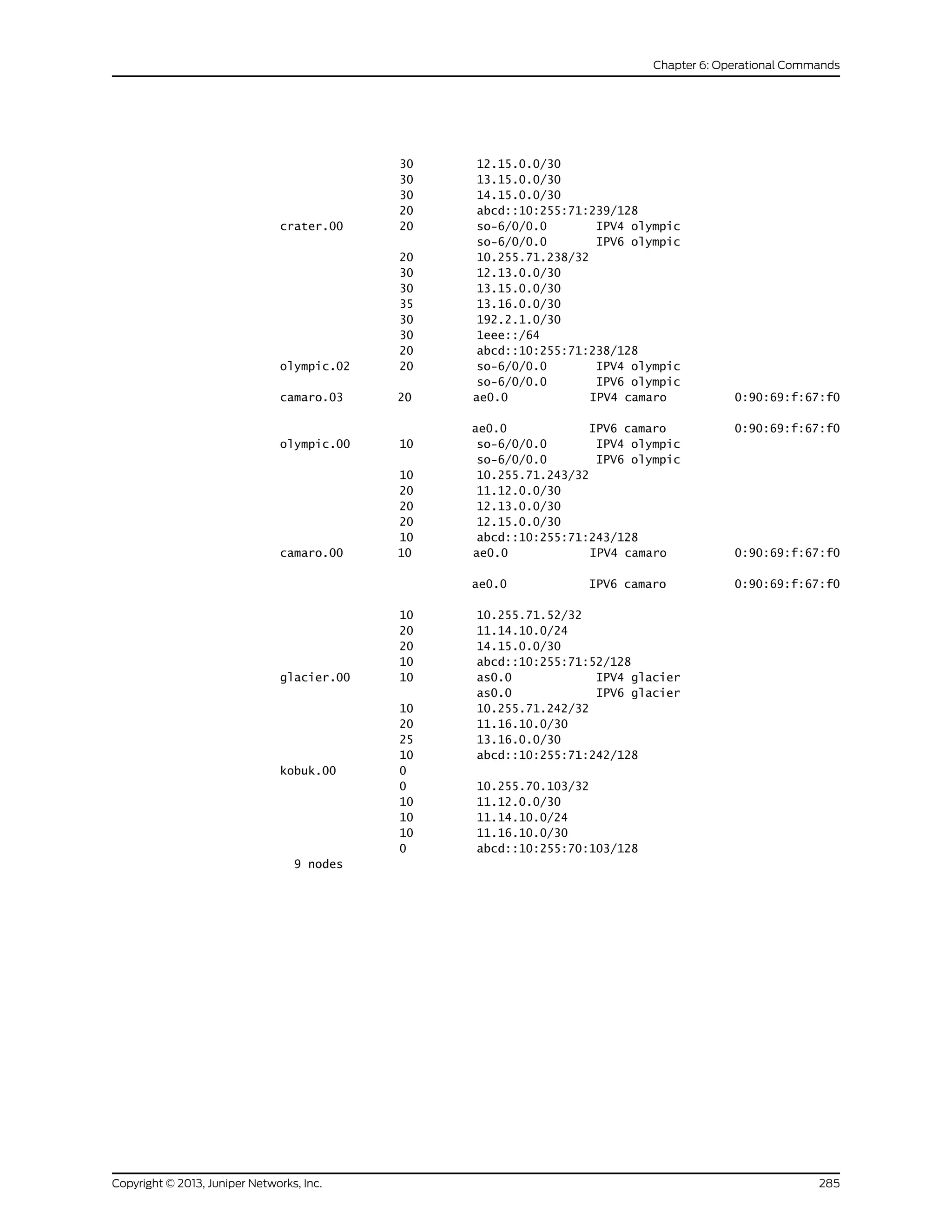
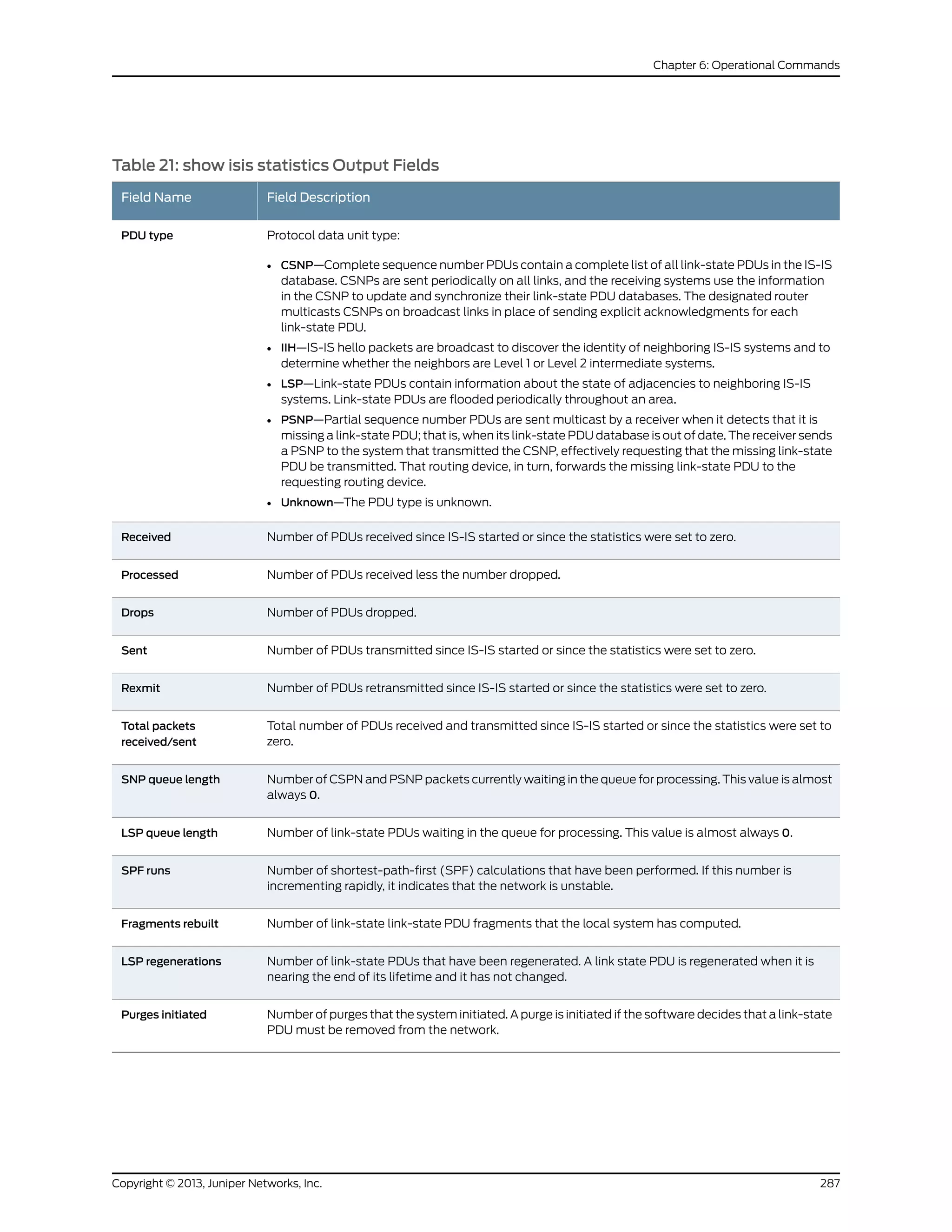
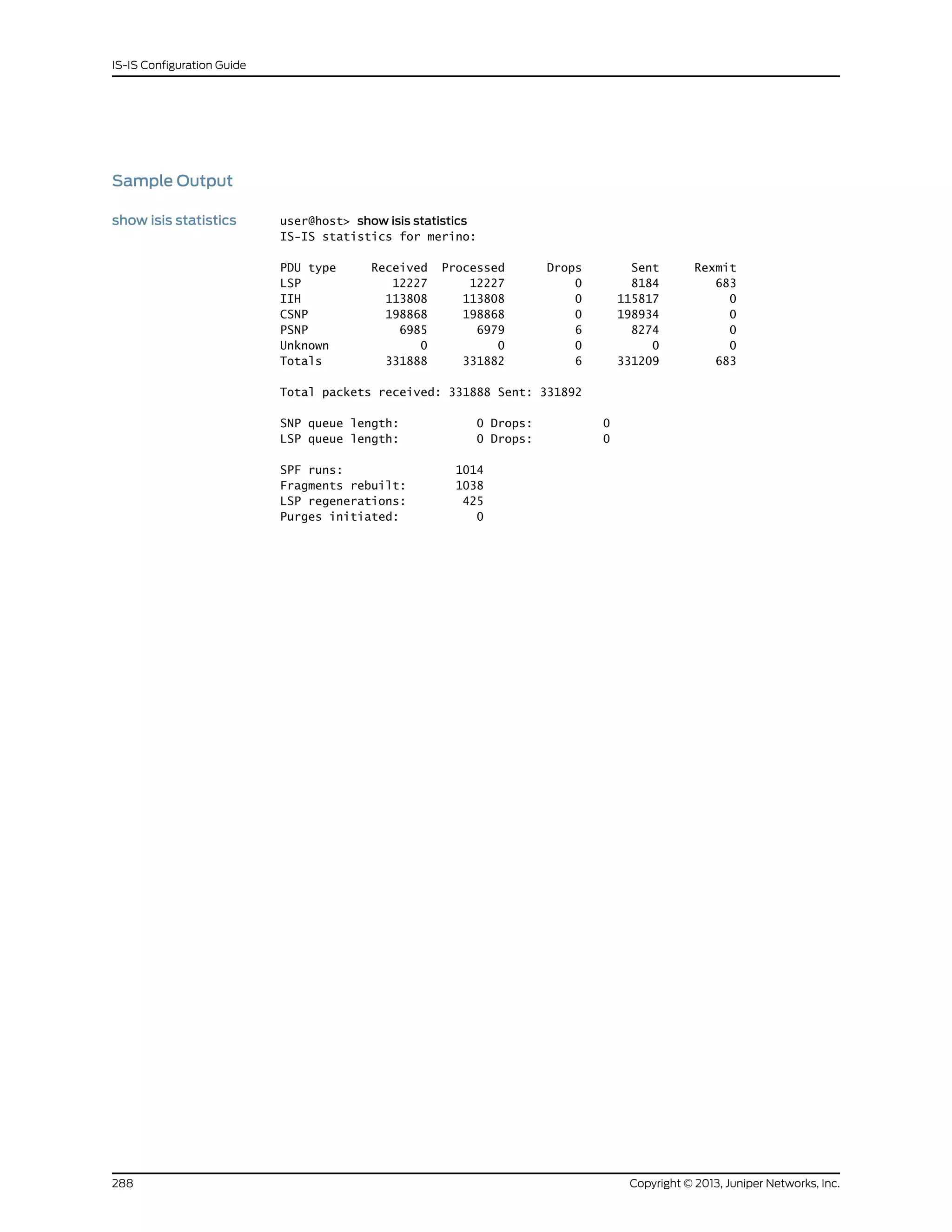
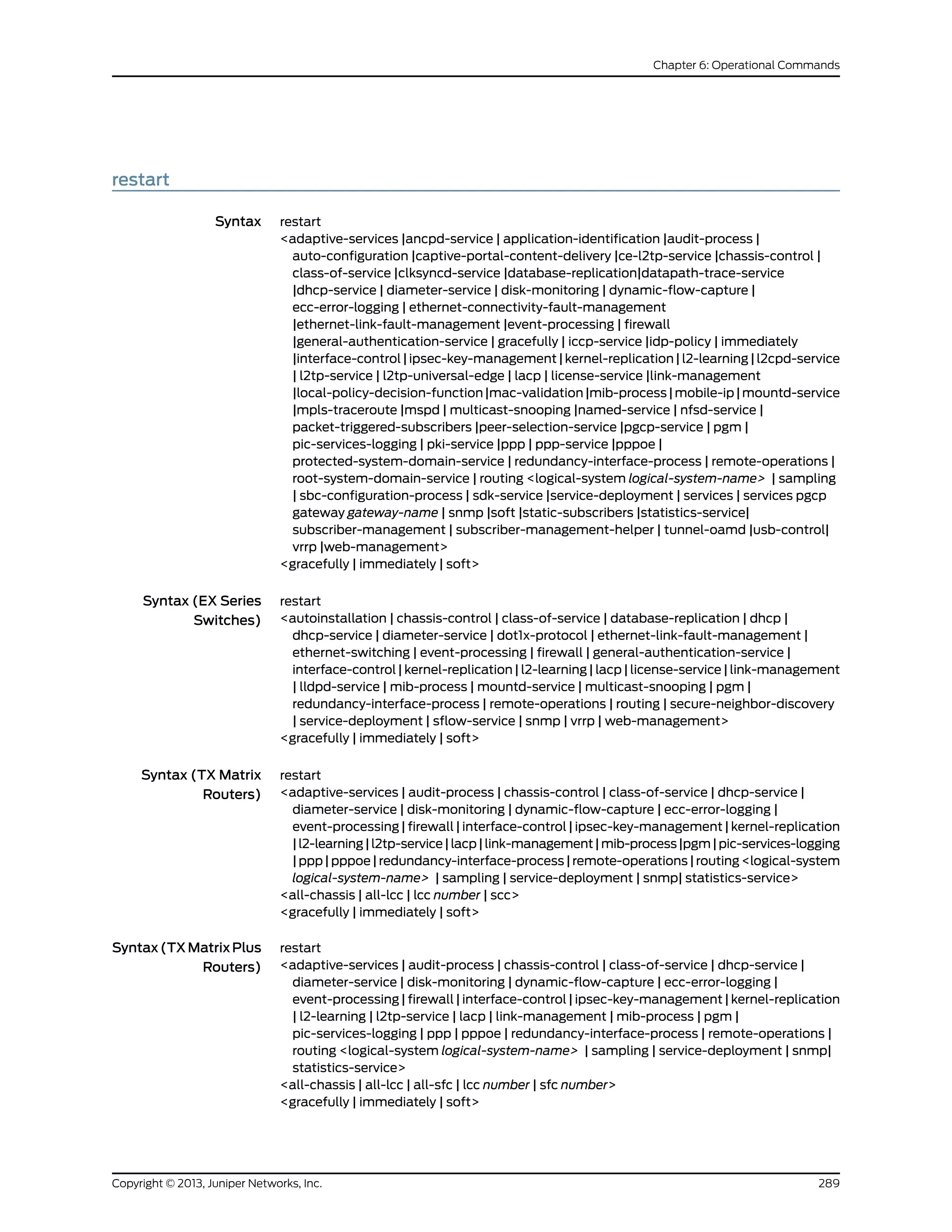

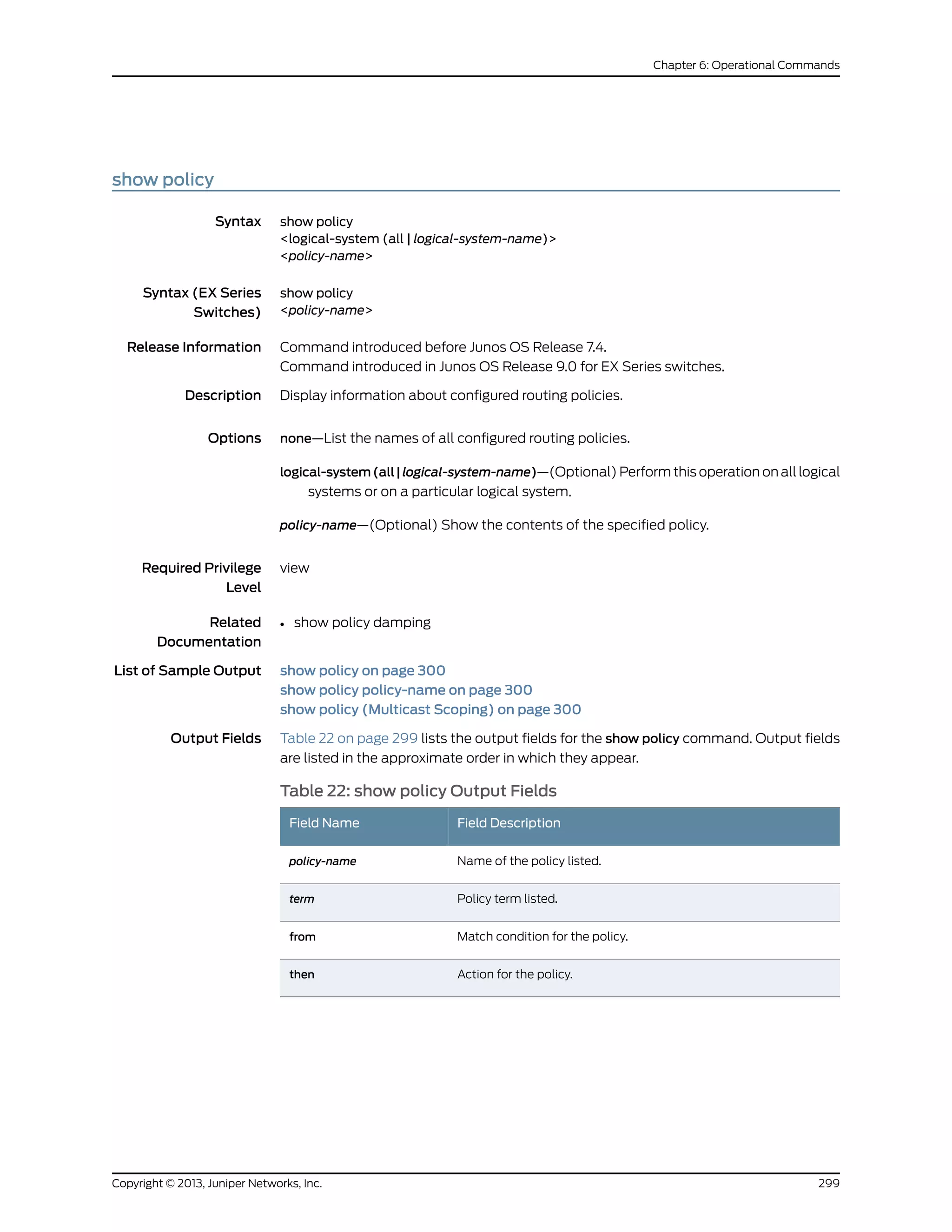
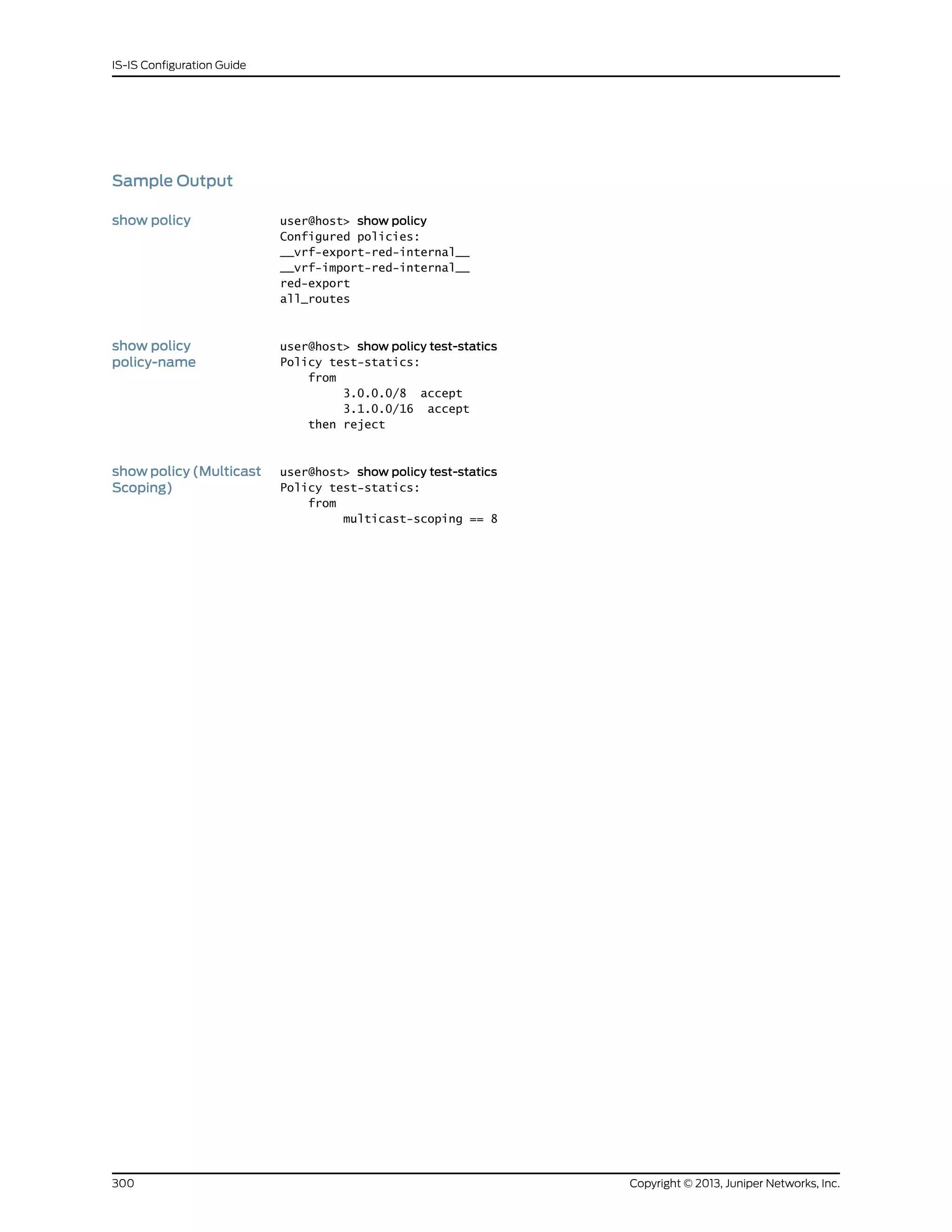
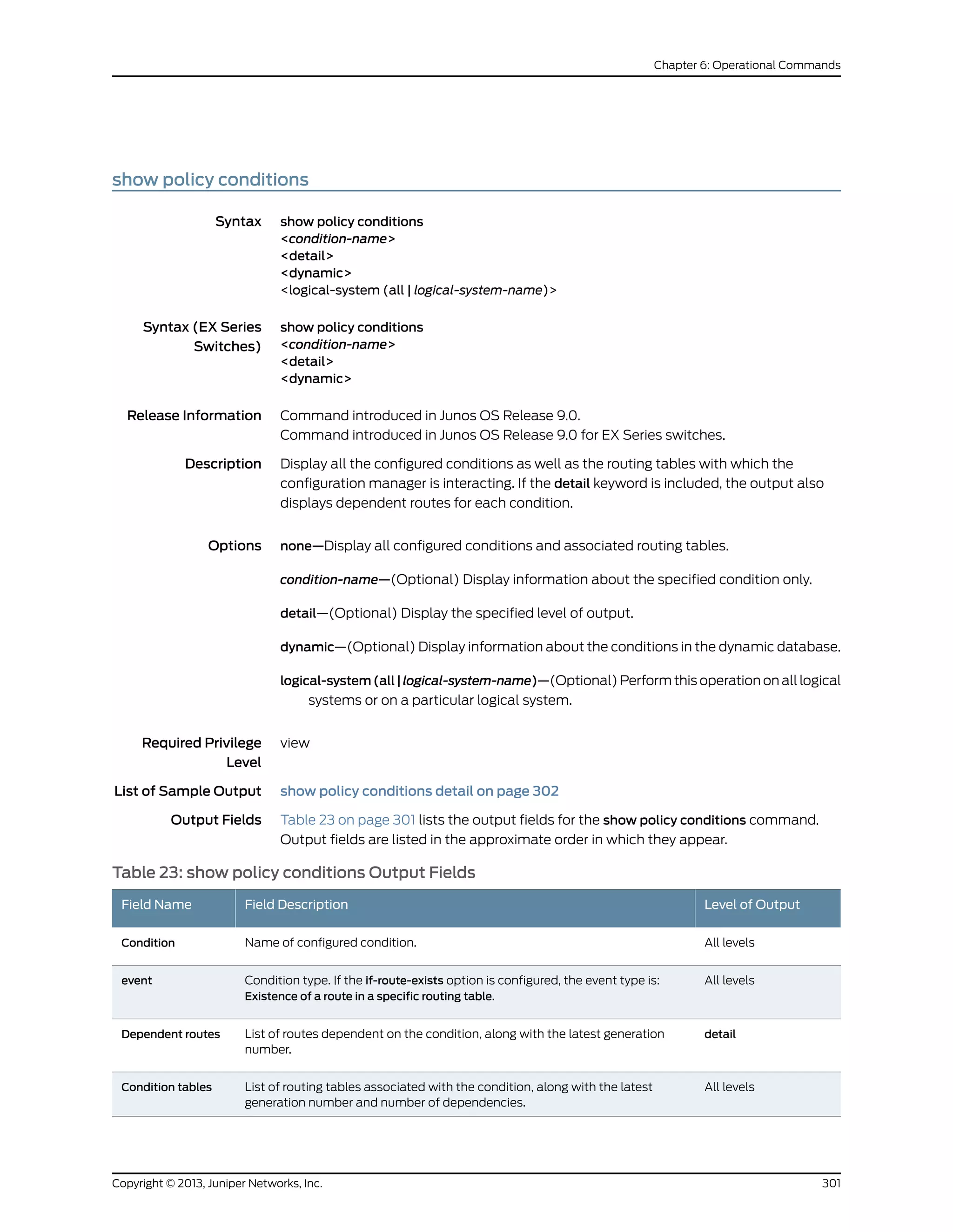
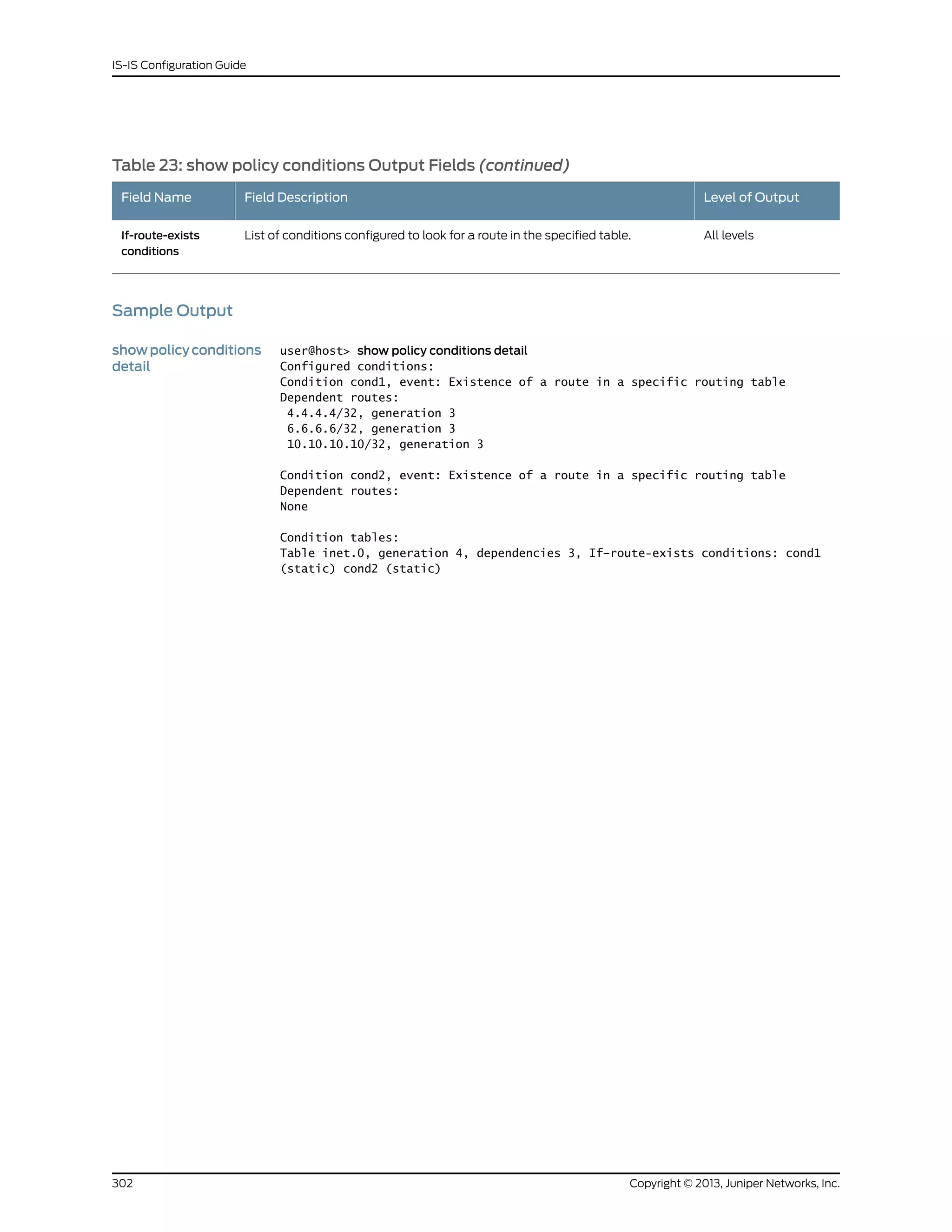
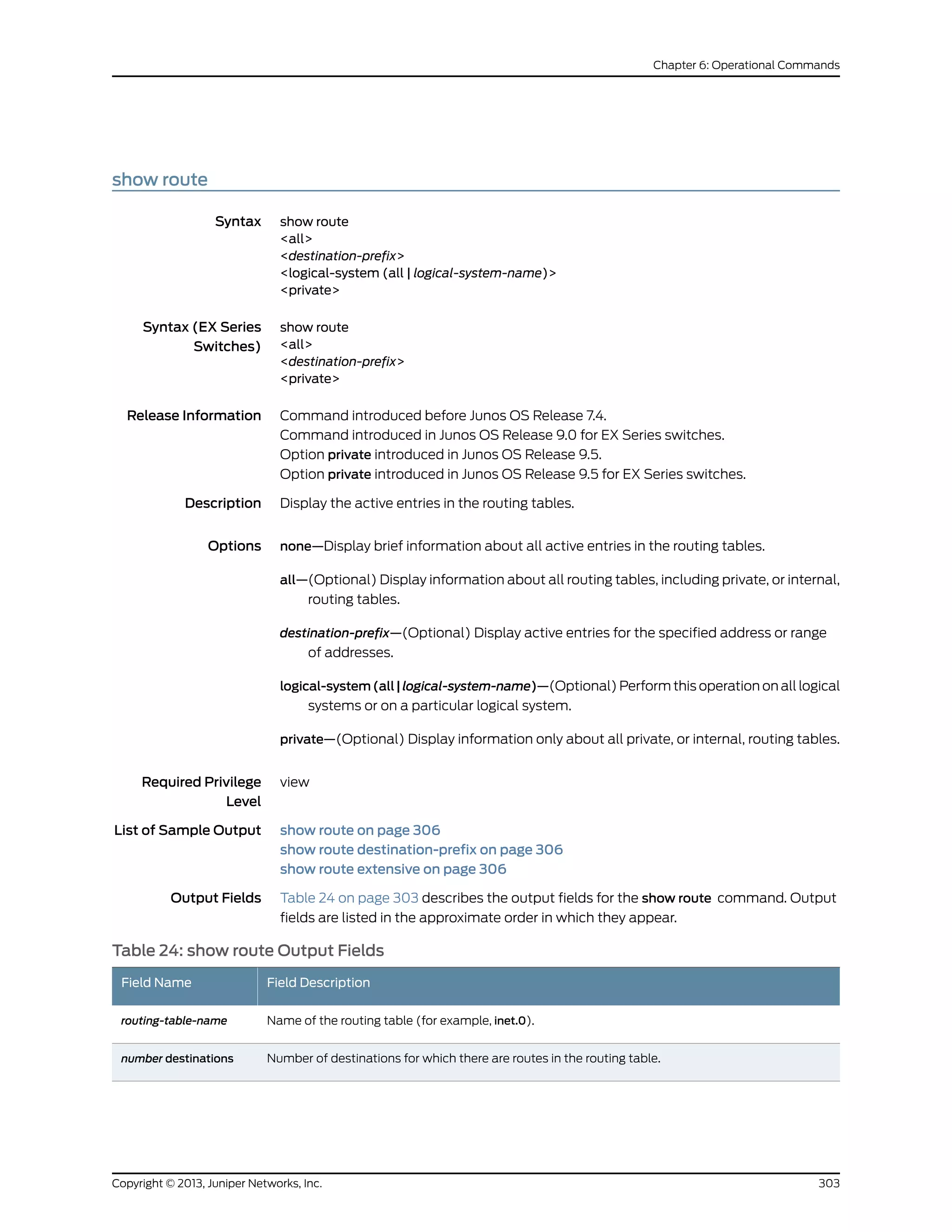
![Table 24: show route Output Fields (continued)
Field DescriptionField Name
Number of routes in the routing table and total number of routes in the following states:
• active (routes that are active).
• holddown (routes that are in the pending state before being declared inactive). A holddown route
was once the active route and is no longer the active route. The route is in the holddown state
because a protocol still has interest in the route, meaning that the interest bit is set. A protocol
might have its interest bit set on the previously active route because the protocol is still advertising
the route. The route will be deleted after all protocols withdraw their advertisement of the route
and remove their interest bit. A persistent holddown state often means that the interested protocol
is not releasing its interest bit properly.
However, if you have configured advertisement of multiple routes (with the add-path or
advertise-inactive statement), the holddown bit is most likely set because BGP is advertising the
route as an active route. In this case, you can ignore the holddown state because nothing is wrong.
• hidden (routes that are not used because of a routing policy).
number routes
Route destination (for example:10.0.0.1/24). Sometimes the route information is presented in another
format, such as:
• MPLS-label (for example, 80001).
• interface-name (for example, ge-1/0/2).
• neighbor-address:control-word-status:encapsulationtype:vc-id:source (Layer 2 circuit only; for example,
10.1.1.195:NoCtrlWord:1:1:Local/96):
• neighbor-address—Address of the neighbor.
• control-word-status—Whether the use of the control word has been negotiated for this virtual
circuit: NoCtrlWord or CtrlWord.
• encapsulation type—Type of encapsulation, represented by a number: (1) Frame Relay DLCI, (2)
ATM AAL5 VCC transport, (3) ATM transparent cell transport, (4) Ethernet, (5) VLAN Ethernet,
(6) HDLC, (7) PPP, (8) ATM VCC cell transport, (10) ATM VPC cell transport.
• vc-id—Virtual circuit identifier.
• source—Source of the advertisement: Local or Remote.
destination-prefix
Protocol from which the route was learned and the preference value for the route.
• +—A plus sign indicates the active route, which is the route installed from the routing table into the
forwarding table.
• - —A hyphen indicates the last active route.
• *—An asterisk indicates that the route is both the active and the last active route. An asterisk before
a to line indicates the best subpath to the route.
In every routing metric except for the BGP LocalPref attribute, a lesser value is preferred. In order to
use common comparison routines, Junos OS stores the 1's complement of the LocalPref value in the
Preference2 field. For example, if the LocalPref value for Route 1 is 100, the Preference2 value is -101.
If the LocalPref value for Route 2 is 155, the Preference2 value is -156. Route 2 is preferred because it
has a higher LocalPref value and a lower Preference2 value.
[ protocol, preference ]
How long the route been known (for example, 2w4d 13:11:14, or 2 weeks, 4 days, 13 hours, 11 minutes,
and 14 seconds).
weeks:days
hours:minutes:seconds
Cost value of the indicated route. For routes within an AS, the cost is determined by the IGP and the
individual protocol metrics. For external routes, destinations, or routing domains, the cost is determined
by a preference value.
metric
Copyright © 2013, Juniper Networks, Inc.304
IS-IS Configuration Guide](https://image.slidesharecdn.com/config-guide-routing-is-is-151104131021-lva1-app6891/75/Juniper-MX-Config-guide-routing-is-is-324-2048.jpg)
![Table 24: show route Output Fields (continued)
Field DescriptionField Name
Local preference value included in the route.localpref
Interface from which the route was received.from
AS path through which the route was learned. The letters at the end of the AS path indicate the path
origin, providing an indication of the state of the route at the point at which the AS path originated:
• I—IGP.
• E—EGP.
• ?—Incomplete; typically, the AS path was aggregated.
When AS path numbers are included in the route, the format is as follows:
• [ ]—Brackets enclose the local AS number associated with the AS path if more than one AS number
is configured on the routing device, or if AS path prepending is configured.
• { }—Braces enclose AS sets, which are groups of AS numbers in which the order does not matter.
A set commonly results from route aggregation. The numbers in each AS set are displayed in
ascending order.
• ( )—Parentheses enclose a confederation.
• ( [ ] )—Parentheses and brackets enclose a confederation set.
NOTE: In Junos OS Release 10.3 and later, the AS path field displays an unrecognized attribute and
associated hexadecimal value if BGP receives attribute 128 (attribute set) and you have not configured
an independent domain in any routing instance.
AS path
(BGP-learned routes) Validation status of the route:
• Invalid—Indicates that the prefix is found, but either the corresponding AS received from the EBGP
peer is not the AS that appears in the database, or the prefix length in the BGP update message is
longer than the maximum length permitted in the database.
• Unknown—Indicates that the prefix is not among the prefixes or prefix ranges in the database.
• Valid—Indicates that the prefix and autonomous system pair are found in the database.
validation-state
Next hop to the destination. An angle bracket (>) indicates that the route is the selected route.to
Interface used to reach the next hop. If there is more than one interface available to the next hop, the
interface that is actually used is followed by the word Selected. This field can also contain the following
information:
• Weight—Value used to distinguish primary, secondary, and fast reroute backup routes. Weight
information is available when MPLS label-switched path (LSP) link protection, node-link protection,
or fast reroute is enabled, or when the standby state is enabled for secondary paths. A lower weight
value is preferred. Among routes with the same weight value, load balancing is possible.
• Balance—Balance coefficient indicating how traffic of unequal cost is distributed among next hops
when a routing device is performing unequal-cost load balancing. This information is available
when you enable BGP multipath load balancing.
• lsp-path-name—Name of the LSP used to reach the next hop.
• label-action—MPLS label and operation occurring at the next hop. The operation can be pop (where
a label is removed from the top of the stack), push (where another label is added to the label stack),
or swap (where a label is replaced by another label).
via
305Copyright © 2013, Juniper Networks, Inc.
Chapter 6: Operational Commands](https://image.slidesharecdn.com/config-guide-routing-is-is-151104131021-lva1-app6891/75/Juniper-MX-Config-guide-routing-is-is-325-2048.jpg)
![Sample Output
show route user@host> show route
inet.0: 11 destinations, 12 routes (11 active, 0 holddown, 0 hidden)
+ = Active Route, - = Last Active, * = Both
1:65500:1:10.0.0.20/240
*[MVPN/70] 19:53:41, metric2 1
Indirect
1:65500:1:10.0.0.40/240
*[BGP/170] 19:53:29, localpref 100, from 10.0.0.30
AS path: I
> to 10.0.24.4 via lt-0/3/0.24, label-switched-path toD
[BGP/170] 19:53:26, localpref 100, from 10.0.0.33
AS path: I
> to 10.0.24.4 via lt-0/3/0.24, label-switched-path toD
1:65500:1:10.0.0.60/240
*[BGP/170] 19:53:29, localpref 100, from 10.0.0.30
AS path: I
> to 10.0.28.8 via lt-0/3/0.28, label-switched-path toF
[BGP/170] 19:53:25, localpref 100, from 10.0.0.33
AS path: I
> to 10.0.28.8 via lt-0/3/0.28, label-switched-path toF
show route
destination-prefix
user@host> show route 172.16.0.0/12
inet.0: 10 destinations, 10 routes (9 active, 0 holddown, 1 hidden)
+ = Active Route, - = Last Active, * = Both
172.16.0.0/12 *[Static/5] 2w4d 12:54:27
> to 192.168.167.254 via fxp0.0
show route extensive user@host> show route extensive
v1.mvpn.0: 5 destinations, 8 routes (5 active, 1 holddown, 0 hidden)
1:65500:1:10.0.0.40/240 (1 entry, 1 announced)
*BGP Preference: 170/-101
PMSI: Flags 0x0: Label[0:0:0]: PIM-SM: Sender 10.0.0.40 Group 225.1.1.1
Next hop type: Indirect
Address: 0x92455b8
Next-hop reference count: 2
Source: 10.0.0.30
Protocol next hop: 10.0.0.40
Indirect next hop: 2 no-forward
State: <Active Int Ext>
Local AS: 65500 Peer AS: 65500
Age: 3 Metric2: 1
Task: BGP_65500.10.0.0.30+179
Announcement bits (2): 0-PIM.v1 1-mvpn global task
AS path: I (Originator) Cluster list: 10.0.0.30
AS path: Originator ID: 10.0.0.40
Communities: target:65520:100
Import Accepted
Localpref: 100
Router ID: 10.0.0.30
Primary Routing Table bgp.mvpn.0
Indirect next hops: 1
Protocol next hop: 10.0.0.40 Metric: 1
Copyright © 2013, Juniper Networks, Inc.306
IS-IS Configuration Guide](https://image.slidesharecdn.com/config-guide-routing-is-is-151104131021-lva1-app6891/75/Juniper-MX-Config-guide-routing-is-is-326-2048.jpg)

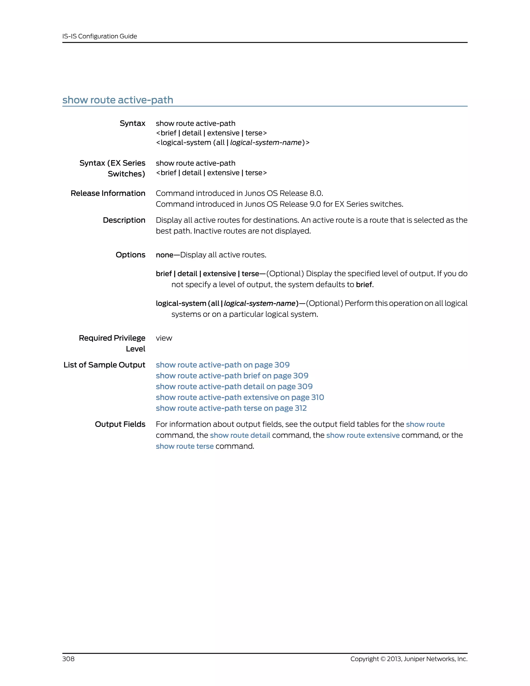
![Sample Output
showrouteactive-path user@host> show route active-path
inet.0: 7 destinations, 7 routes (6 active, 0 holddown, 1 hidden)
+ = Active Route, - = Last Active, * = Both
10.255.70.19/32 *[Direct/0] 21:33:52
> via lo0.0
10.255.71.50/32 *[IS-IS/15] 00:18:13, metric 10
> to 100.1.2.1 via so-2/1/3.0
100.1.2.0/24 *[Direct/0] 00:18:36
> via so-2/1/3.0
100.1.2.2/32 *[Local/0] 00:18:41
Local via so-2/1/3.0
192.168.64.0/21 *[Direct/0] 21:33:52
> via fxp0.0
192.168.70.19/32 *[Local/0] 21:33:52
Local via fxp0.0
showrouteactive-path
brief
The output for the show route active-path brief command is identical to that for the show
route active-path command. For sample output, see show route active-path on page 309.
showrouteactive-path
detail
user@host> show route active-path detail
inet.0: 7 destinations, 7 routes (6 active, 0 holddown, 1 hidden)
10.255.70.19/32 (1 entry, 1 announced)
*Direct Preference: 0
Next hop type: Interface
Next-hop reference count: 3
Next hop: via lo0.0, selected
State: ‹Active Int›
Local AS: 200
Age: 21:37:10
Task: IF
Announcement bits (3): 2-IS-IS 5-Resolve tree 2 6-Resolve tree 3
AS path: I
10.255.71.50/32 (1 entry, 1 announced)
*IS-IS Preference: 15
Level: 1
Next hop type: Router, Next hop index: 397
Next-hop reference count: 4
Next hop: 100.1.2.1 via so-2/1/3.0, selected
State: ‹Active Int›
Local AS: 200
Age: 21:31 Metric: 10
Task: IS-IS
Announcement bits (4): 0-KRT 2-IS-IS 5-Resolve tree 2 6-Resolve
tree 3
AS path: I
100.1.2.0/24 (1 entry, 1 announced)
*Direct Preference: 0
Next hop type: Interface
Next-hop reference count: 3
309Copyright © 2013, Juniper Networks, Inc.
Chapter 6: Operational Commands](https://image.slidesharecdn.com/config-guide-routing-is-is-151104131021-lva1-app6891/75/Juniper-MX-Config-guide-routing-is-is-329-2048.jpg)
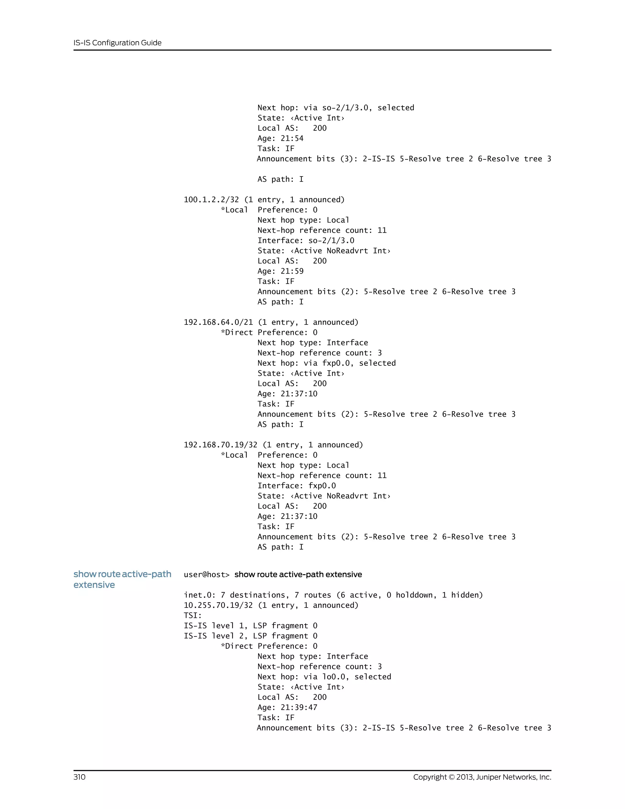
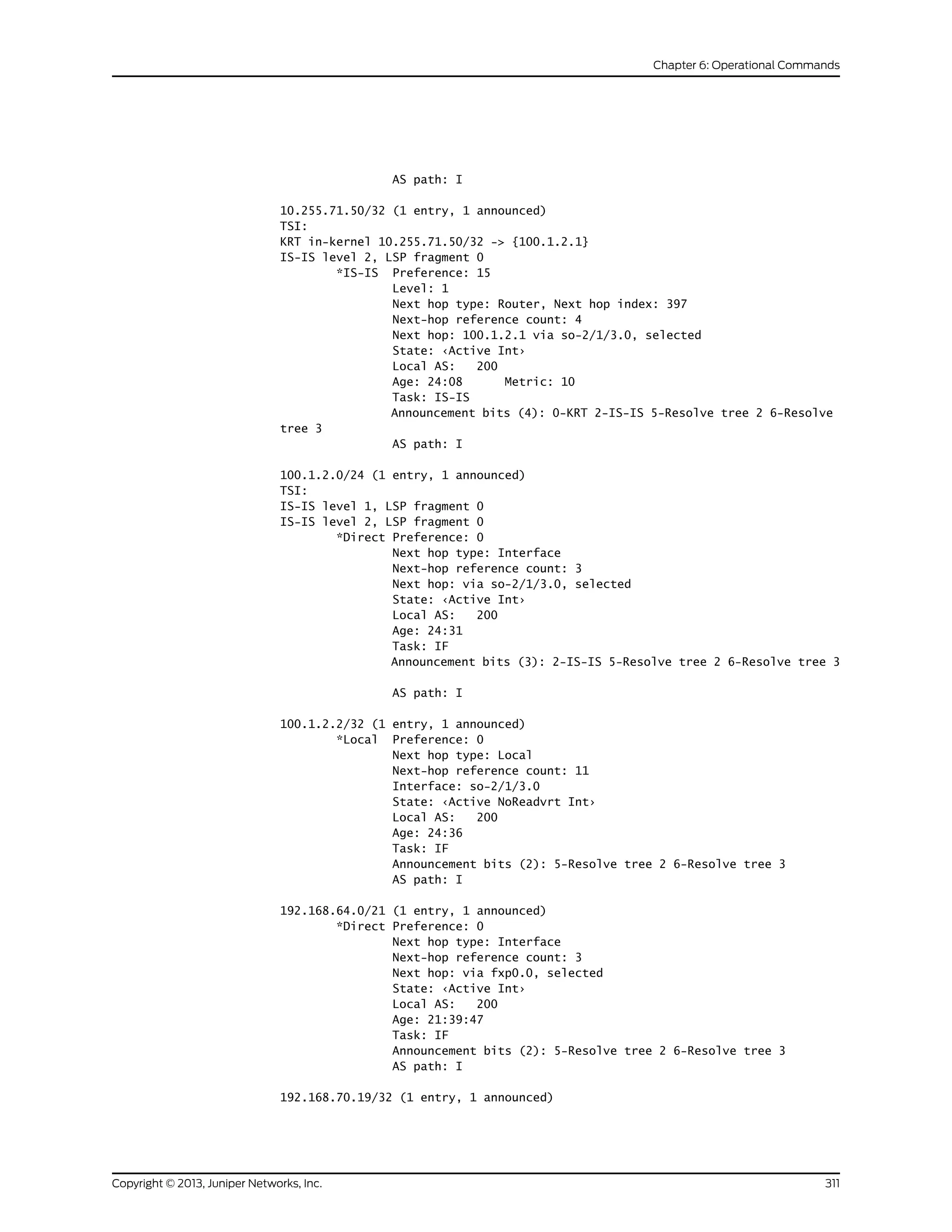
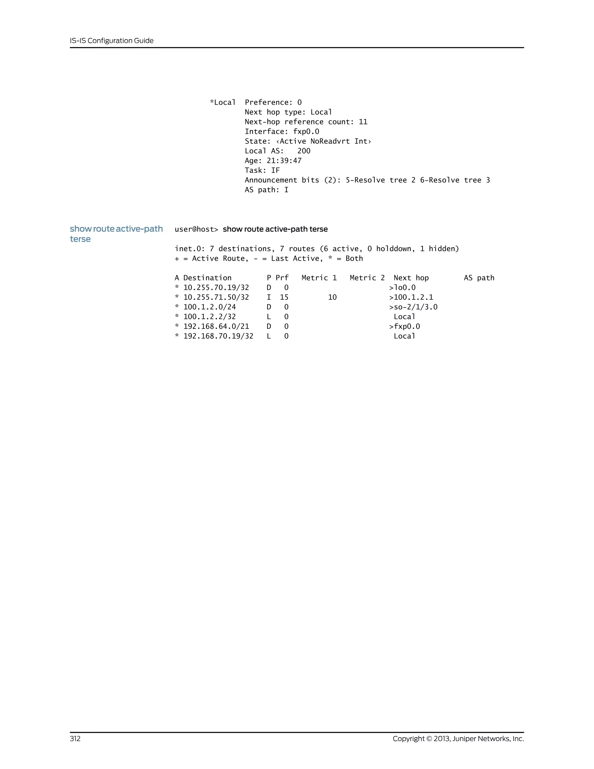
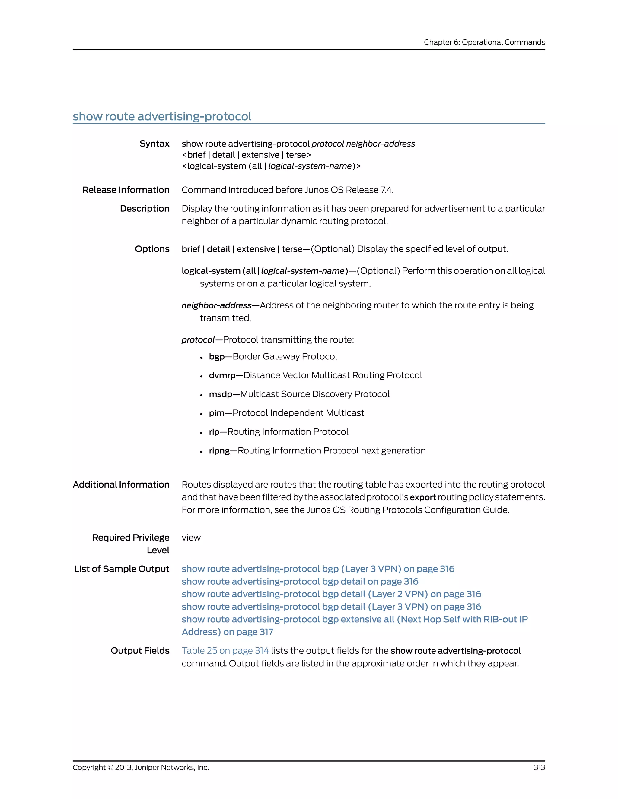
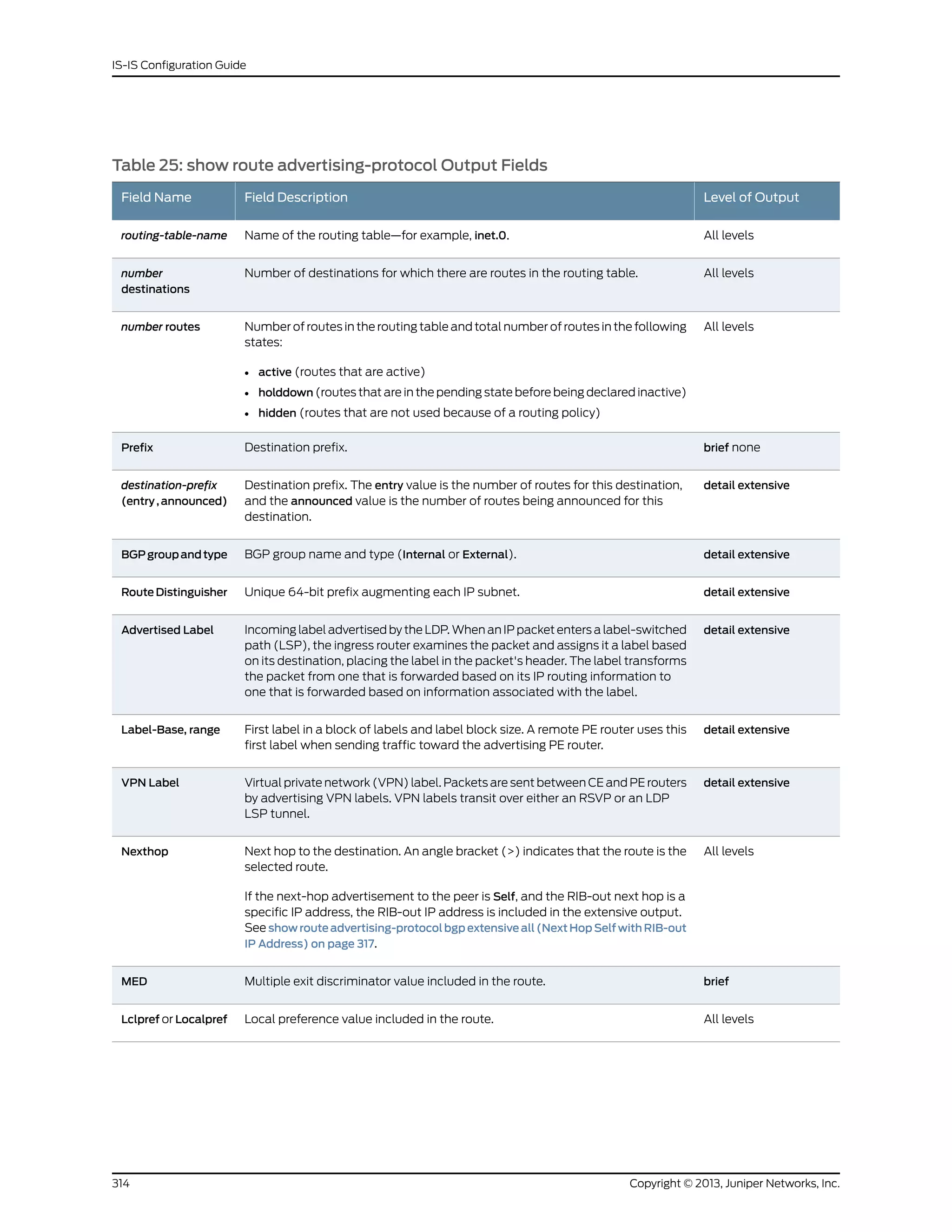
![Table 25: show route advertising-protocol Output Fields (continued)
Level of OutputField DescriptionField Name
All levelsAS path through which the route was learned. The letters at the end of the AS
path indicate the path origin, providing an indication of the state of the route at
the point at which the AS path originated:
• I—IGP.
• E—EGP.
• ?—Incomplete; typically, the AS path was aggregated.
When AS path numbers are included in the route, the format is as follows:
• [ ]—Brackets enclose the local AS number associated with the AS path if
configured on the router, or if AS path prepending is configured.
• { }—Braces enclose AS sets, which are groups of AS numbers in which the
order does not matter. A set commonly results from route aggregation. The
numbers in each AS set are displayed in ascending order.
• ( )—Parentheses enclose a confederation.
• ( [ ] )—Parentheses and brackets enclose a confederation set.
NOTE: In Junos OS Release 10.3 and later, the AS path field displays an
unrecognized attribute and associated hexadecimal value if BGP receives
attribute 128 (attribute set) and you have not configured an independent domain
in any routing instance.
AS path
detail extensiveCommunity path attribute for the route. See the output field table for the show
route detail command for all possible values for this field.
Communities
detail extensiveAccumulated interior gateway protocol (AIGP) BGP attribute.AIGP
detail extensiveNumber, local preference, and path of the autonomous system (AS) that
originated the route. These values are stored in the Attrset attribute at the
originating router.
Attrset AS
detail extensiveLayer 2 encapsulation (for example, VPLS).Layer2-info: encaps
detail extensiveControl flags: none or Site Down.control flags
detail extensiveMaximum transmission unit (MTU) of the Layer 2 circuit.mtu
315Copyright © 2013, Juniper Networks, Inc.
Chapter 6: Operational Commands](https://image.slidesharecdn.com/config-guide-routing-is-is-151104131021-lva1-app6891/75/Juniper-MX-Config-guide-routing-is-is-335-2048.jpg)
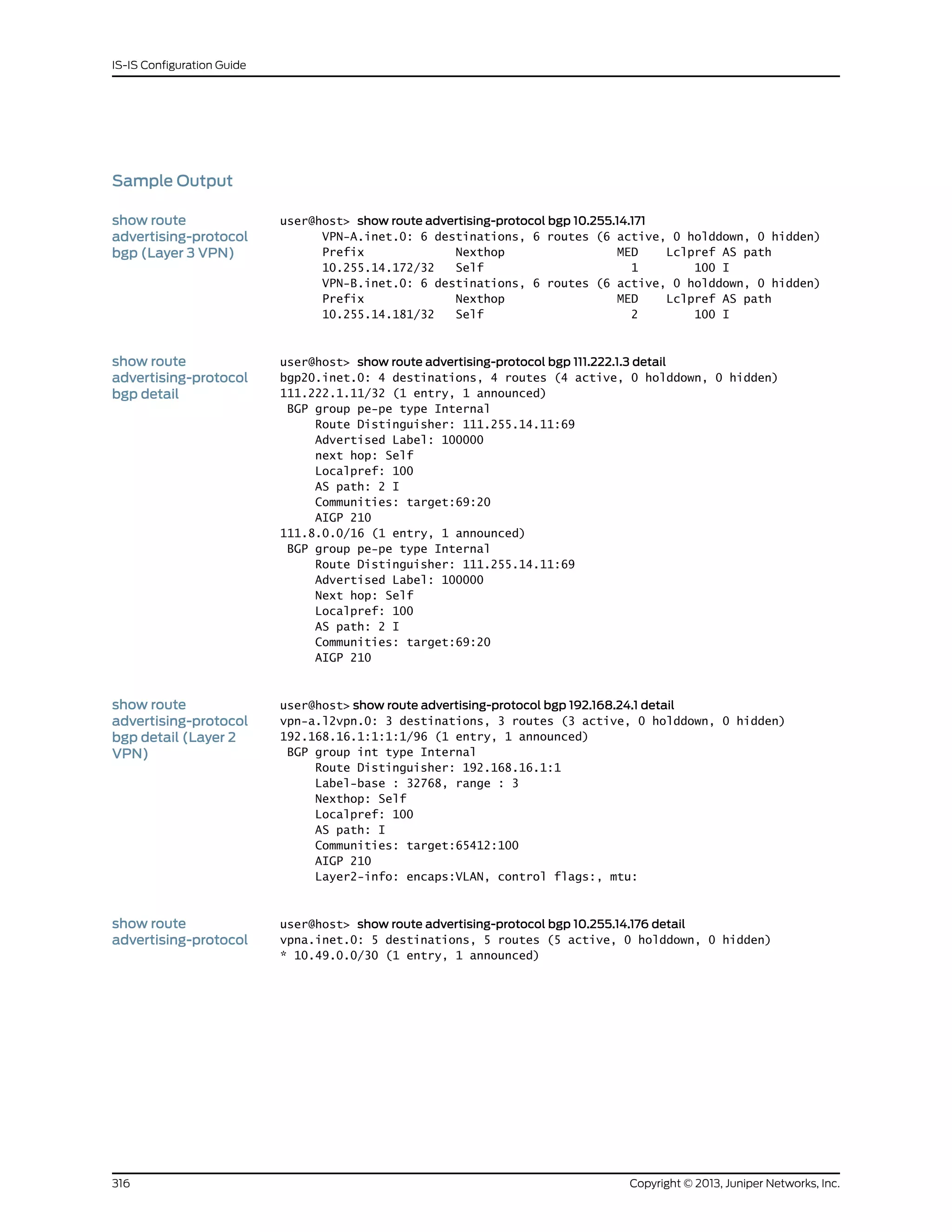
![BGP group ibgp type Internal
Route Distinguisher: 10.255.14.174:2
bgp detail (Layer 3
VPN)
VPN Label: 101264
Nexthop: Self
Localpref: 100
AS path: I
Communities: target:200:100
AIGP 210
AttrSet AS: 100
Localpref: 100
AS path: I
...
show route
advertising-protocol
user@host> show route advertising-protocol bgp 200.0.0.2 170.0.1.0/24 extensive all
inet.0: 13 destinations, 19 routes (13 active, 0 holddown, 6 hidden)
170.0.1.0/24 (2 entries, 1 announced)bgpextensiveall(Next
BGP group eBGP-INTEROP type ExternalHop Self with RIB-out
IP Address) Nexthop: Self (rib-out 10.100.3.2)
AS path: [4713] 200 I
...
317Copyright © 2013, Juniper Networks, Inc.
Chapter 6: Operational Commands](https://image.slidesharecdn.com/config-guide-routing-is-is-151104131021-lva1-app6891/75/Juniper-MX-Config-guide-routing-is-is-337-2048.jpg)
![Sample Output
show route all The following example displays a snippet of output from the show route command and
then displays the same snippet of output from the show route all command:
user@host> show route
mpls.0: 7 destinations, 7 routes (5 active, 0 holddown, 2 hidden)
Restart Complete
+ = Active Route, - = Last Active, * = Both
0 *[MPLS/0] 2d 02:24:39, metric 1
Receive
1 *[MPLS/0] 2d 02:24:39, metric 1
Receive
2 *[MPLS/0] 2d 02:24:39, metric 1
Receive
800017 *[VPLS/7] 1d 14:00:16
> via vt-3/2/0.32769, Pop
800018 *[VPLS/7] 1d 14:00:26
> via vt-3/2/0.32772, Pop
user@host> show route all
mpls.0: 7 destinations, 7 routes (5 active, 0 holddown, 2 hidden)
Restart Complete
+ = Active Route, - = Last Active, * = Both
0 *[MPLS/0] 2d 02:19:12, metric 1
Receive
1 *[MPLS/0] 2d 02:19:12, metric 1
Receive
2 *[MPLS/0] 2d 02:19:12, metric 1
Receive
800017 *[VPLS/7] 1d 13:54:49
> via vt-3/2/0.32769, Pop
800018 *[VPLS/7] 1d 13:54:59
> via vt-3/2/0.32772, Pop
vt-3/2/0.32769 [VPLS/7] 1d 13:54:49
Unusable
vt-3/2/0.32772 [VPLS/7] 1d 13:54:59
Unusable
319Copyright © 2013, Juniper Networks, Inc.
Chapter 6: Operational Commands](https://image.slidesharecdn.com/config-guide-routing-is-is-151104131021-lva1-app6891/75/Juniper-MX-Config-guide-routing-is-is-339-2048.jpg)
![Sample Output
show route best user@host> show route best 10.255.70.103
inet.0: 24 destinations, 25 routes (23 active, 0 holddown, 1 hidden)
Restart Complete
+ = Active Route, - = Last Active, * = Both
10.255.70.103/32 *[OSPF/10] 1d 13:19:20, metric 2
> to 10.31.1.6 via ge-3/1/0.0
via so-0/3/0.0
inet.3: 2 destinations, 2 routes (2 active, 0 holddown, 0 hidden)
Restart Complete
+ = Active Route, - = Last Active, * = Both
10.255.70.103/32 *[RSVP/7] 1d 13:20:13, metric 2
> via so-0/3/0.0, label-switched-path green-r1-r3
private1__.inet.0: 2 destinations, 3 routes (2 active, 0 holddown, 0 hidden)
+ = Active Route, - = Last Active, * = Both
10.0.0.0/8 *[Direct/0] 2d 01:43:34
> via fxp2.0
[Direct/0] 2d 01:43:34
> via fxp1.0
show route best detail user@host> show route best 10.255.70.103 detail
inet.0: 24 destinations, 25 routes (23 active, 0 holddown, 1 hidden)
Restart Complete
10.255.70.103/32 (1 entry, 1 announced)
*OSPF Preference: 10
Next-hop reference count: 9
Next hop: 10.31.1.6 via ge-3/1/0.0, selected
Next hop: via so-0/3/0.0
State: <Active Int>
Local AS: 69
Age: 1d 13:20:06 Metric: 2
Area: 0.0.0.0
Task: OSPF
Announcement bits (2): 0-KRT 3-Resolve tree 2
AS path: I
inet.3: 2 destinations, 2 routes (2 active, 0 holddown, 0 hidden)
Restart Complete
10.255.70.103/32 (1 entry, 1 announced)
State: <FlashAll>
*RSVP Preference: 7
Next-hop reference count: 5
Next hop: via so-0/3/0.0 weight 0x1, selected
Label-switched-path green-r1-r3
Label operation: Push 100016
State: <Active Int>
Local AS: 69
Age: 1d 13:20:59 Metric: 2
Task: RSVP
Announcement bits (1): 1-Resolve tree 2
AS path: I
private1__inet.0: 2 destinations, 3 routes (2 active, 0 holddown, 0 hidden)
10.0.0.0/8 (2 entries, 0 announced)
*Direct Preference: 0
Next hop type: Interface
321Copyright © 2013, Juniper Networks, Inc.
Chapter 6: Operational Commands](https://image.slidesharecdn.com/config-guide-routing-is-is-151104131021-lva1-app6891/75/Juniper-MX-Config-guide-routing-is-is-341-2048.jpg)
![Sample Output
show route brief user@host> show route brief
inet.0: 10 destinations, 10 routes (9 active, 0 holddown, 1 hidden)
+ = Active Route, - = Last Active, * = Both
0.0.0.0/0 *[Static/5] 1w5d 20:30:29
Discard
10.255.245.51/32 *[Direct/0] 2w4d 13:11:14
> via lo0.0
172.16.0.0/12 *[Static/5] 2w4d 13:11:14
> to 192.168.167.254 via fxp0.0
192.168.0.0/18 *[Static/5] 1w5d 20:30:29
> to 192.168.167.254 via fxp0.0
192.168.40.0/22 *[Static/5] 2w4d 13:11:14
> to 192.168.167.254 via fxp0.0
192.168.64.0/18 *[Static/5] 2w4d 13:11:14
> to 192.168.167.254 via fxp0.0
192.168.164.0/22 *[Direct/0] 2w4d 13:11:14
> via fxp0.0
192.168.164.51/32 *[Local/0] 2w4d 13:11:14
Local via fxp0.0
207.17.136.192/32 *[Static/5] 2w4d 13:11:14
> to 192.168.167.254 via fxp0.0
Copyright © 2013, Juniper Networks, Inc.324
IS-IS Configuration Guide](https://image.slidesharecdn.com/config-guide-routing-is-is-151104131021-lva1-app6891/75/Juniper-MX-Config-guide-routing-is-is-344-2048.jpg)
![green.inet.0: 3 destinations, 3 routes (3 active, 0 holddown, 0 hidden)
+ = Active Route, - = Last Active, * = Both
100.101.0.0/16 *[Direct/0] 1w5d 20:30:28
> via fe-0/0/3.0
100.101.2.3/32 *[Local/0] 1w5d 20:30:28
Local via fe-0/0/3.0
224.0.0.5/32 *[OSPF/10] 1w5d 20:30:29, metric 1
MultiRecv
325Copyright © 2013, Juniper Networks, Inc.
Chapter 6: Operational Commands](https://image.slidesharecdn.com/config-guide-routing-is-is-151104131021-lva1-app6891/75/Juniper-MX-Config-guide-routing-is-is-345-2048.jpg)
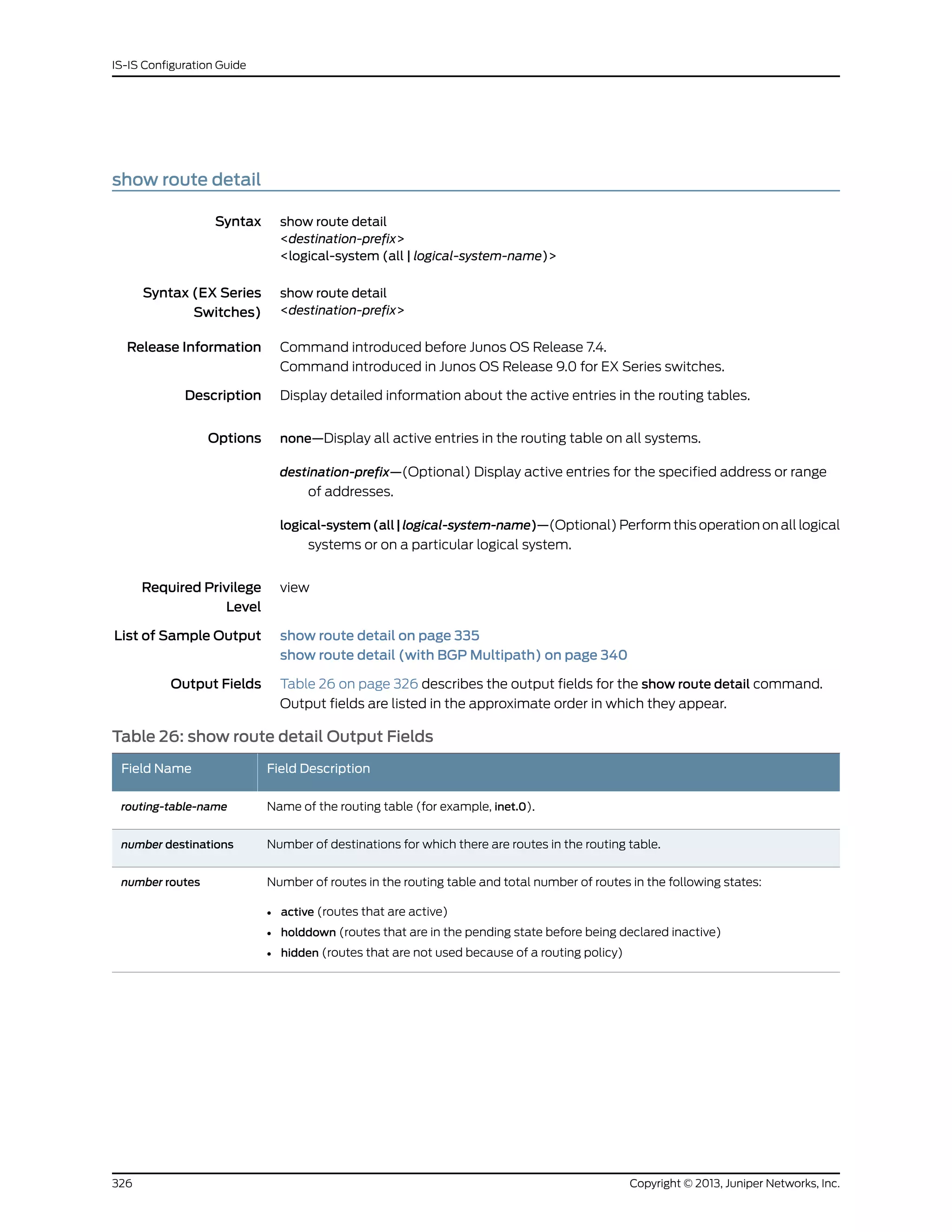
![Table 26: show route detail Output Fields (continued)
Field DescriptionField Name
Route destination (for example:10.0.0.1/24). The entry value is the number of routes for this destination,
and the announced value is the number of routes being announced for this destination. Sometimes
the route destination is presented in another format, such as:
• MPLS-label (for example, 80001).
• interface-name (for example, ge-1/0/2).
• neighbor-address:control-word-status:encapsulationtype:vc-id:source (Layer 2 circuit only; for example,
10.1.1.195:NoCtrlWord:1:1:Local/96).
• neighbor-address—Address of the neighbor.
• control-word-status—Whether the use of the control word has been negotiated for this virtual
circuit: NoCtrlWord or CtrlWord.
• encapsulation type—Type of encapsulation, represented by a number: (1) Frame Relay DLCI, (2)
ATM AAL5 VCC transport, (3) ATM transparent cell transport, (4) Ethernet, (5) VLAN Ethernet,
(6) HDLC, (7) PPP, (8) ATM VCC cell transport, (10) ATM VPC cell transport.
• vc-id—Virtual circuit identifier.
• source—Source of the advertisement: Local or Remote.
route-destination
(entry, announced)
(Next-to-the-last-hop routing device for MPLS only) Depth of the MPLS label stack, where the
label-popping operation is needed to remove one or more labels from the top of the stack. A pair of
routes is displayed, because the pop operation is performed only when the stack depth is two or more
labels.
• S=0 route indicates that a packet with an incoming label stack depth of 2 or more exits this routing
device with one fewer label (the label-popping operation is performed).
• If there is no S= information, the route is a normal MPLS route, which has a stack depth of 1 (the
label-popping operation is not performed).
label stacking
Protocol from which the route was learned and the preference value for the route.
• +—A plus sign indicates the active route, which is the route installed from the routing table into the
forwarding table.
• - —A hyphen indicates the last active route.
• *—An asterisk indicates that the route is both the active and the last active route. An asterisk before
a to line indicates the best subpath to the route.
In every routing metric except for the BGP LocalPref attribute, a lesser value is preferred. In order to
use common comparison routines, Junos OS stores the 1's complement of the LocalPref value in the
Preference2 field. For example, if the LocalPref value for Route 1 is 100, the Preference2 value is -101.
If the LocalPref value for Route 2 is 155, the Preference2 value is -156. Route 2 is preferred because it
has a higher LocalPref value and a lower Preference2 value.
[protocol, preference]
(IS-IS only). In IS-IS, a single AS can be divided into smaller groups called areas. Routing between
areas is organized hierarchically, allowing a domain to be administratively divided into smaller areas.
This organization is accomplished by configuring Level 1 and Level 2 intermediate systems. Level 1
systems route within an area. When the destination is outside an area, they route toward a Level 2
system. Level 2 intermediate systems route between areas and toward other ASs.
Level
IP subnet augmented with a 64-bit prefix.Route Distinguisher
Type of next hop. For a description of possible values for this field, see Table 27 on page 330.Next-hop type
327Copyright © 2013, Juniper Networks, Inc.
Chapter 6: Operational Commands](https://image.slidesharecdn.com/config-guide-routing-is-is-151104131021-lva1-app6891/75/Juniper-MX-Config-guide-routing-is-is-347-2048.jpg)
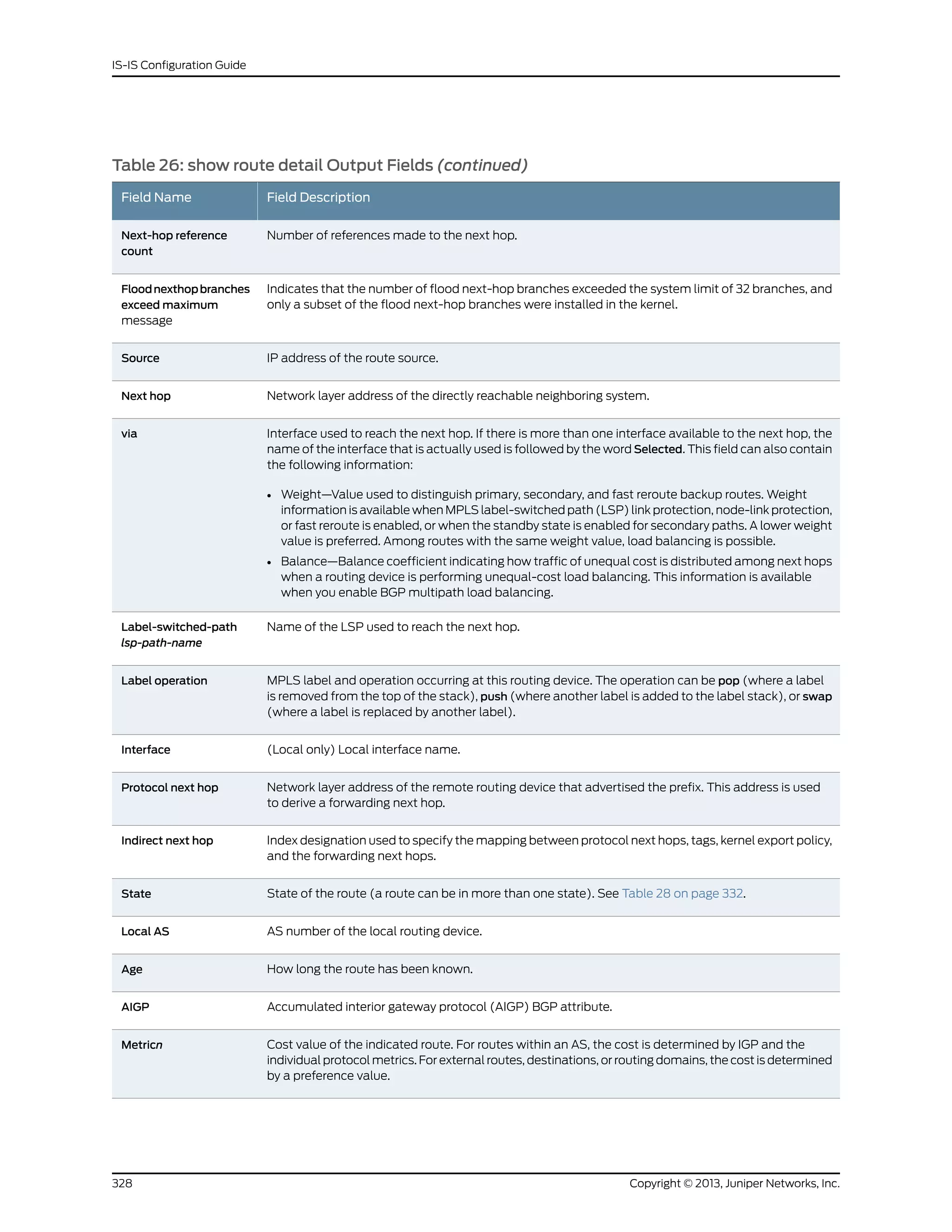
![Table 26: show route detail Output Fields (continued)
Field DescriptionField Name
Metric value for BGP path selection to which the IGP cost to the next-hop destination has been added.MED-plus-IGP
For MPLS LSPs, state of the TTL propagation attribute. Can be enabled or disabled for all
RSVP-signaled and LDP-signaled LSPs or for specific VRF routing instances.
For sample output, see show route table.
TTL-Action
Name of the protocol that has added the route.Task
List of protocols that announce this route. n-Resolve inet indicates that the route is used for route
resolution for next hops found in the routing table. n is an index used by Juniper Networks customer
support only.
Announcement bits
AS path through which the route was learned. The letters at the end of the AS path indicate the path
origin, providing an indication of the state of the route at the point at which the AS path originated:
• I—IGP.
• E—EGP.
• Recorded—The AS path is recorded by the sample process (sampled).
• ?—Incomplete; typically, the AS path was aggregated.
When AS path numbers are included in the route, the format is as follows:
• [ ]—Brackets enclose the number that precedes the AS path. This number represents the number
of ASs present in the AS path, when calculated as defined in RFC 4271. This value is used in the
AS-path merge process, as defined in RFC 4893.
• [ ]—If more than one AS number is configured on the routing device, or if AS path prepending is
configured, brackets enclose the local AS number associated with the AS path.
• { }—Braces enclose AS sets, which are groups of AS numbers in which the order does not matter.
A set commonly results from route aggregation. The numbers in each AS set are displayed in
ascending order.
• ( )—Parentheses enclose a confederation.
• ( [ ] )—Parentheses and brackets enclose a confederation set.
NOTE: In Junos OS Release 10.3 and later, the AS path field displays an unrecognized attribute and
associated hexadecimal value if BGP receives attribute 128 (attribute set) and you have not configured
an independent domain in any routing instance.
AS path
MPLS label assigned to the Layer 2 circuit virtual connection.VC Label
Maximum transmission unit (MTU) of the Layer 2 circuit.MTU
VLAN identifier of the Layer 2 circuit.VLAN ID
Forwarding equivalent class (FEC) bound to this route. Applicable only to routes installed by LDP.Prefixes bound to route
Community path attribute for the route. See Table 29 on page 334 for all possible values for this field.Communities
Layer 2 encapsulation (for example, VPLS).Layer2-info: encaps
329Copyright © 2013, Juniper Networks, Inc.
Chapter 6: Operational Commands](https://image.slidesharecdn.com/config-guide-routing-is-is-151104131021-lva1-app6891/75/Juniper-MX-Config-guide-routing-is-is-349-2048.jpg)
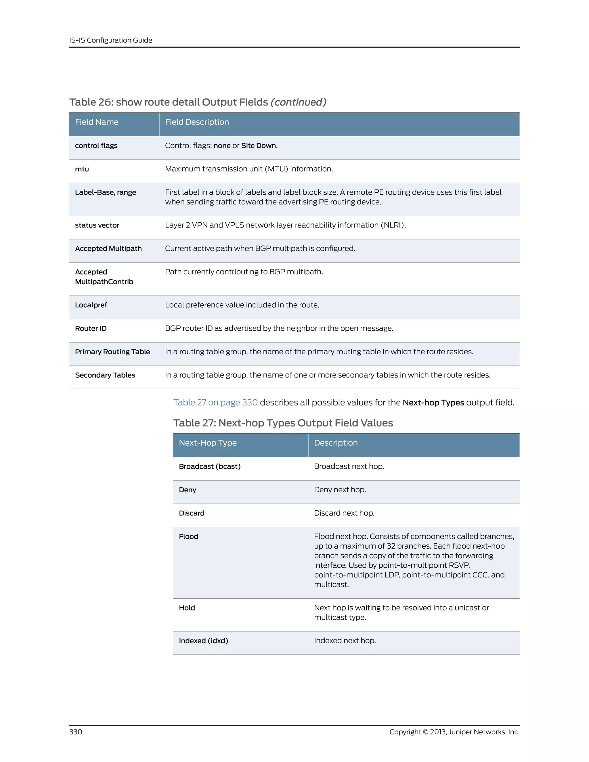
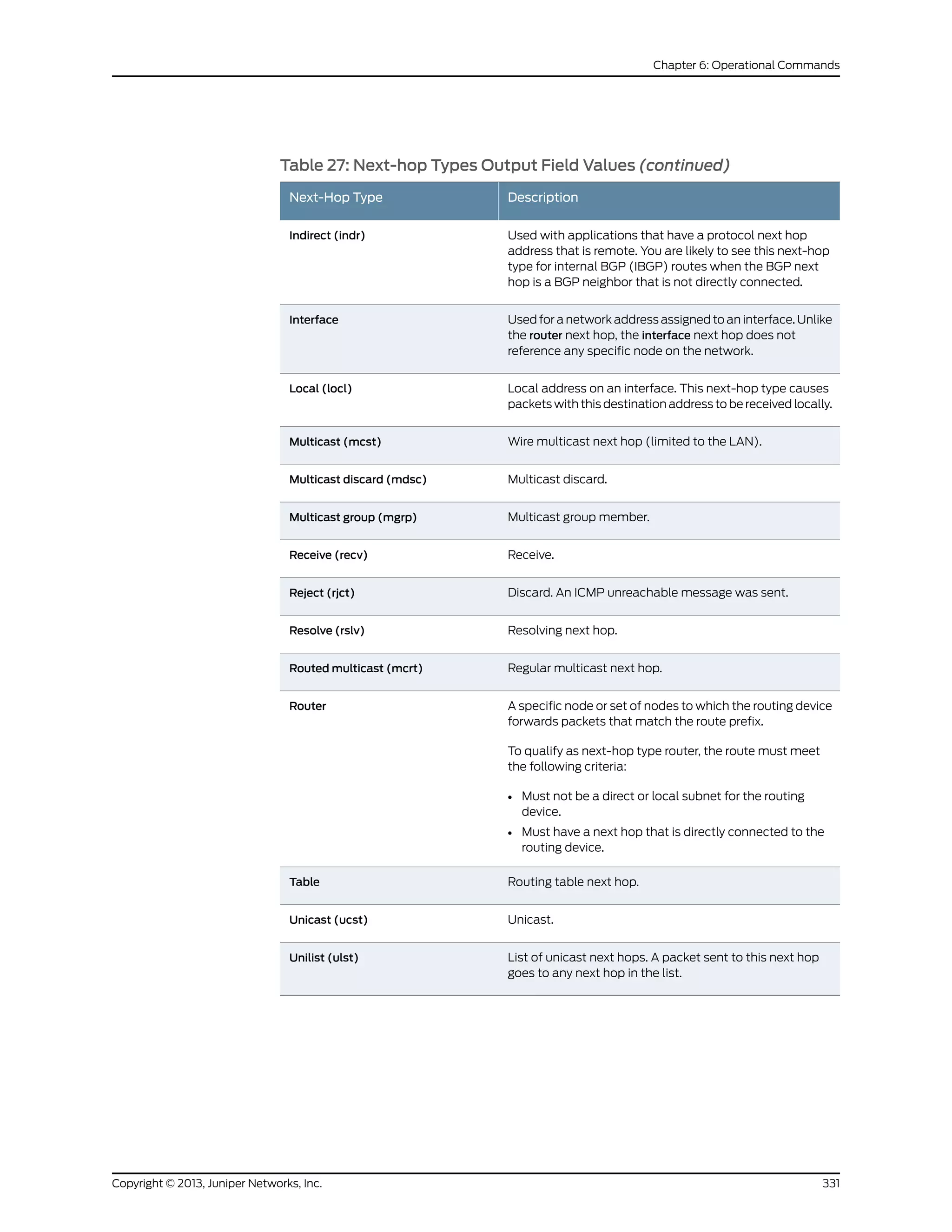
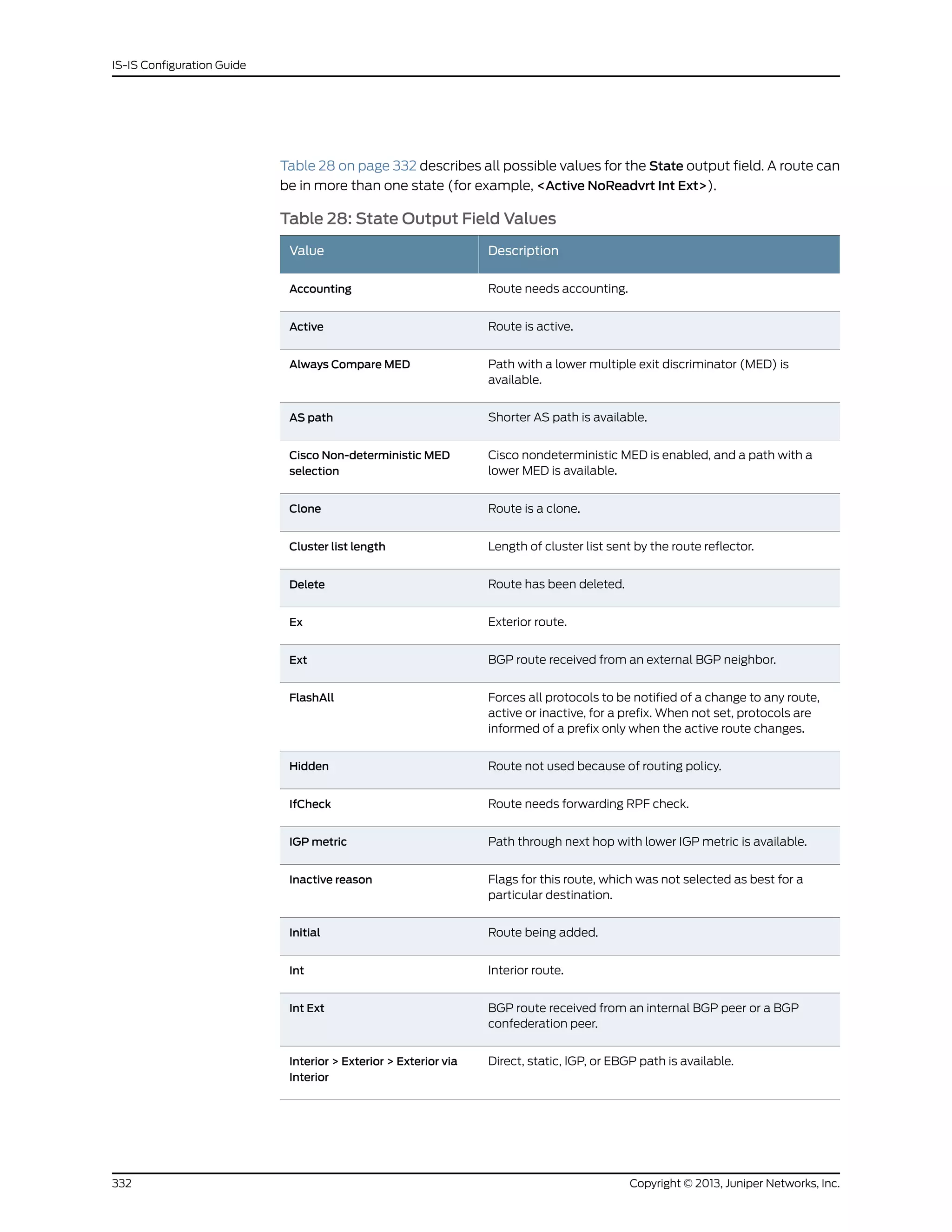
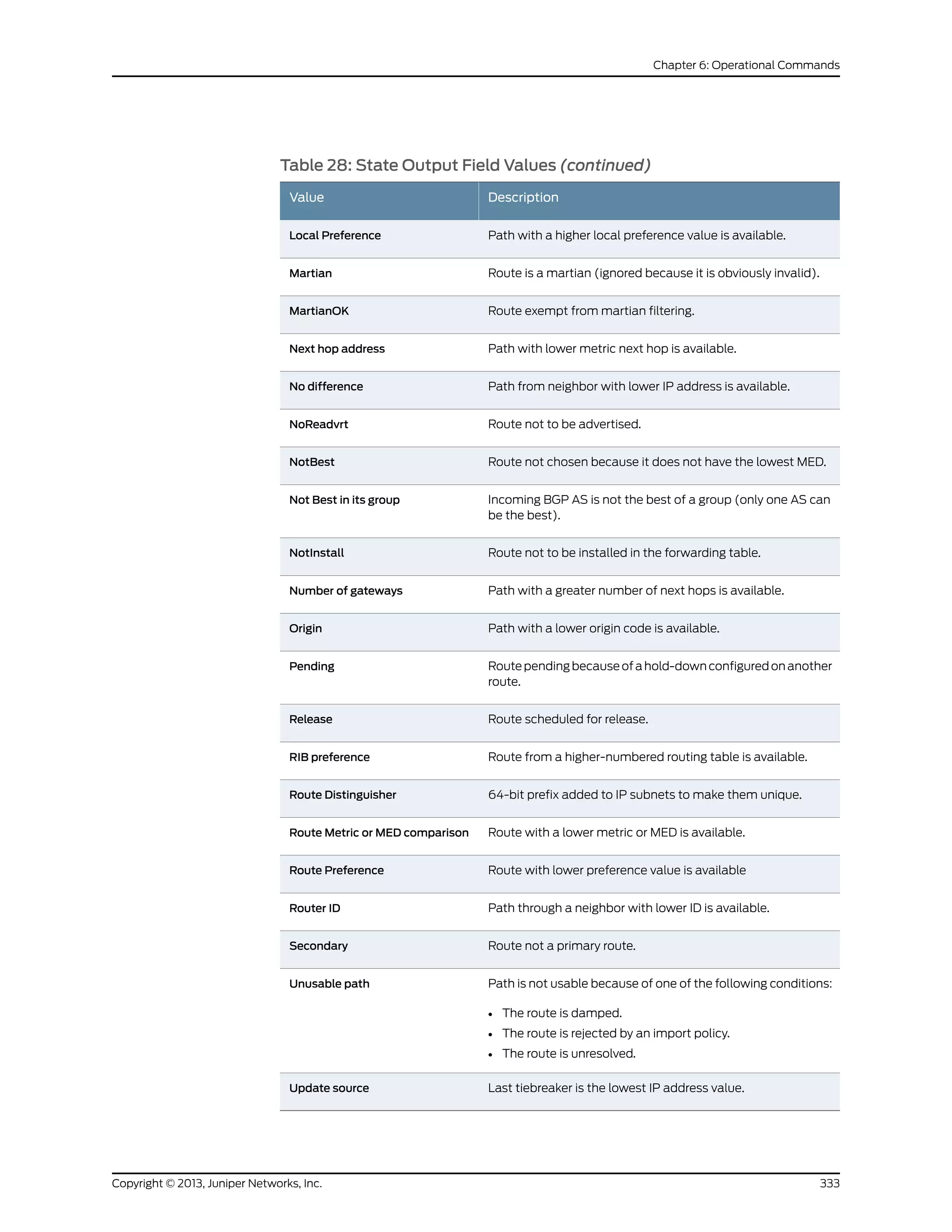
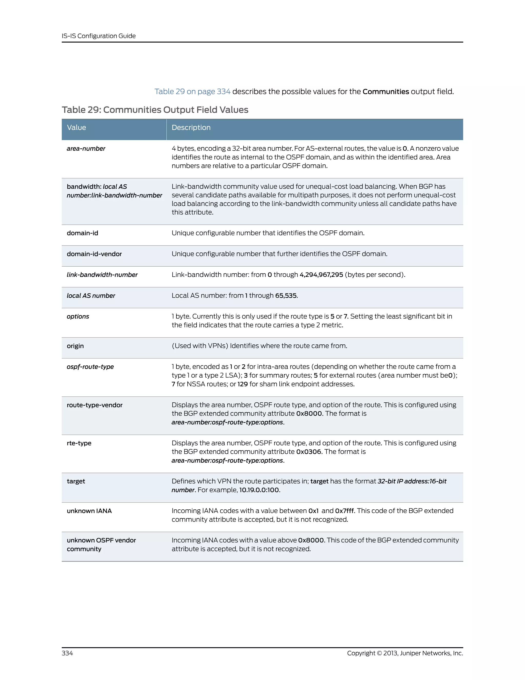
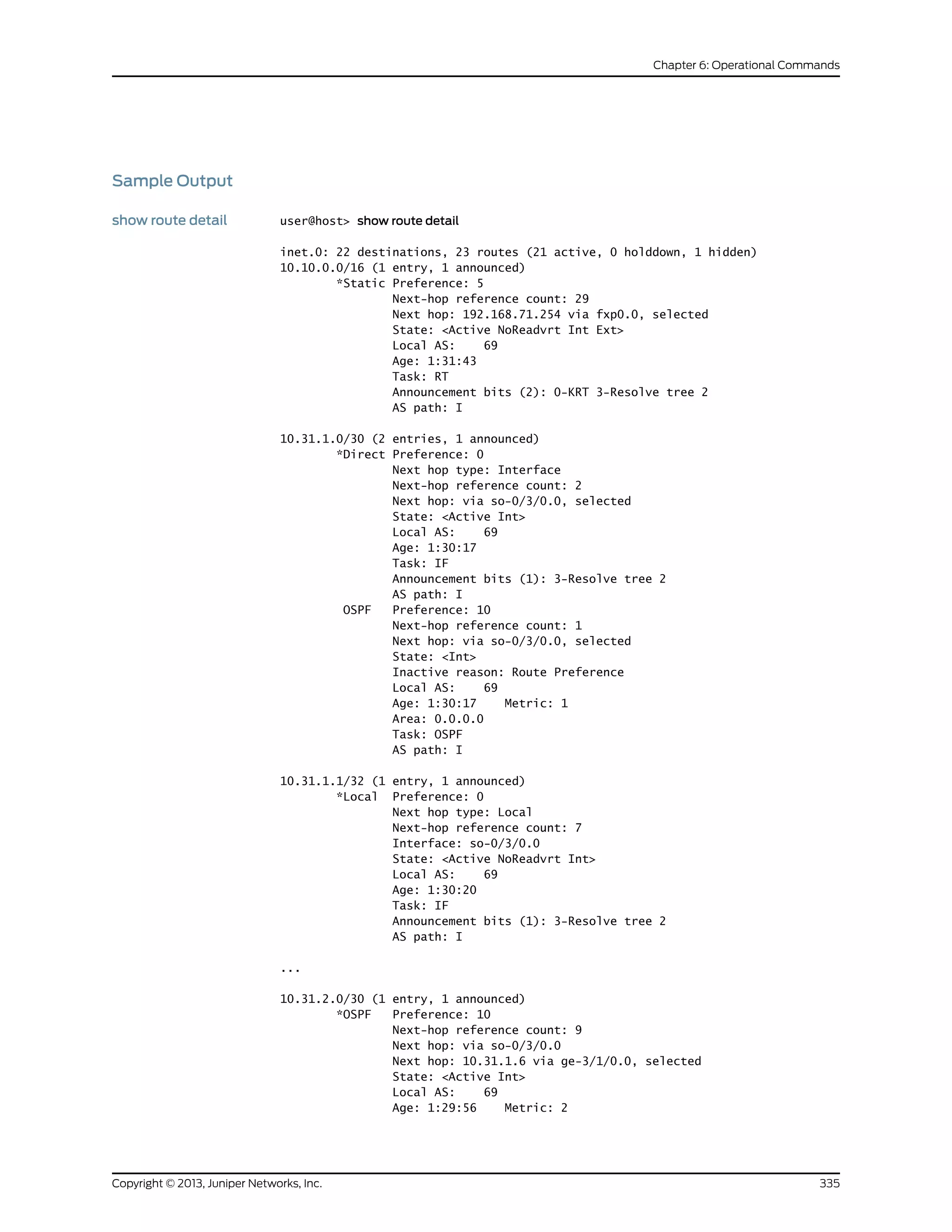
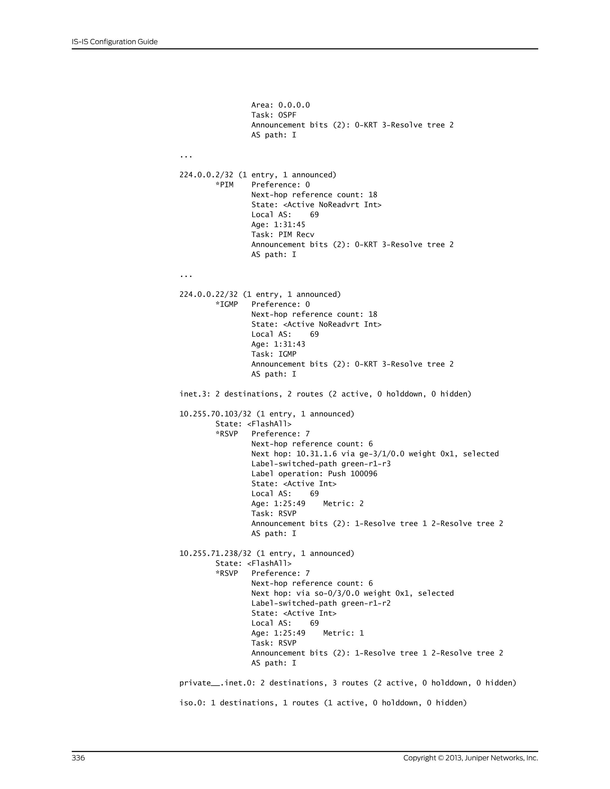
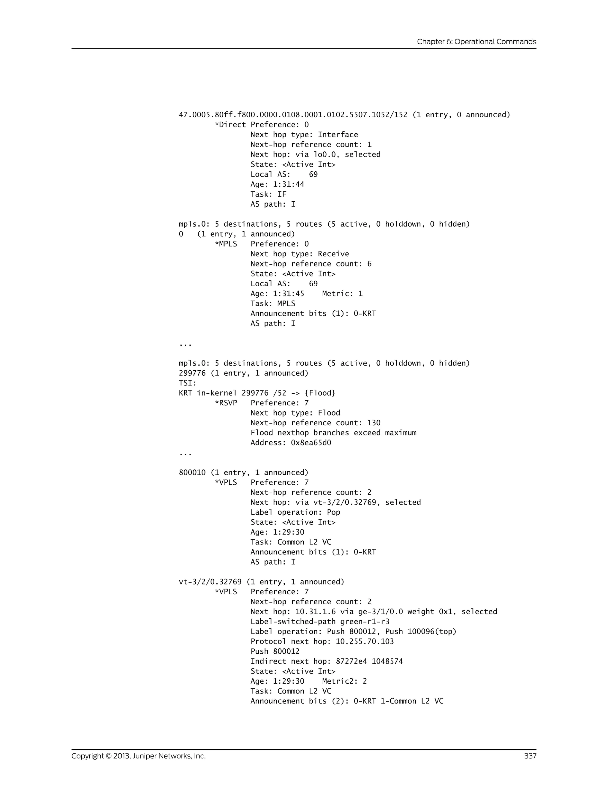
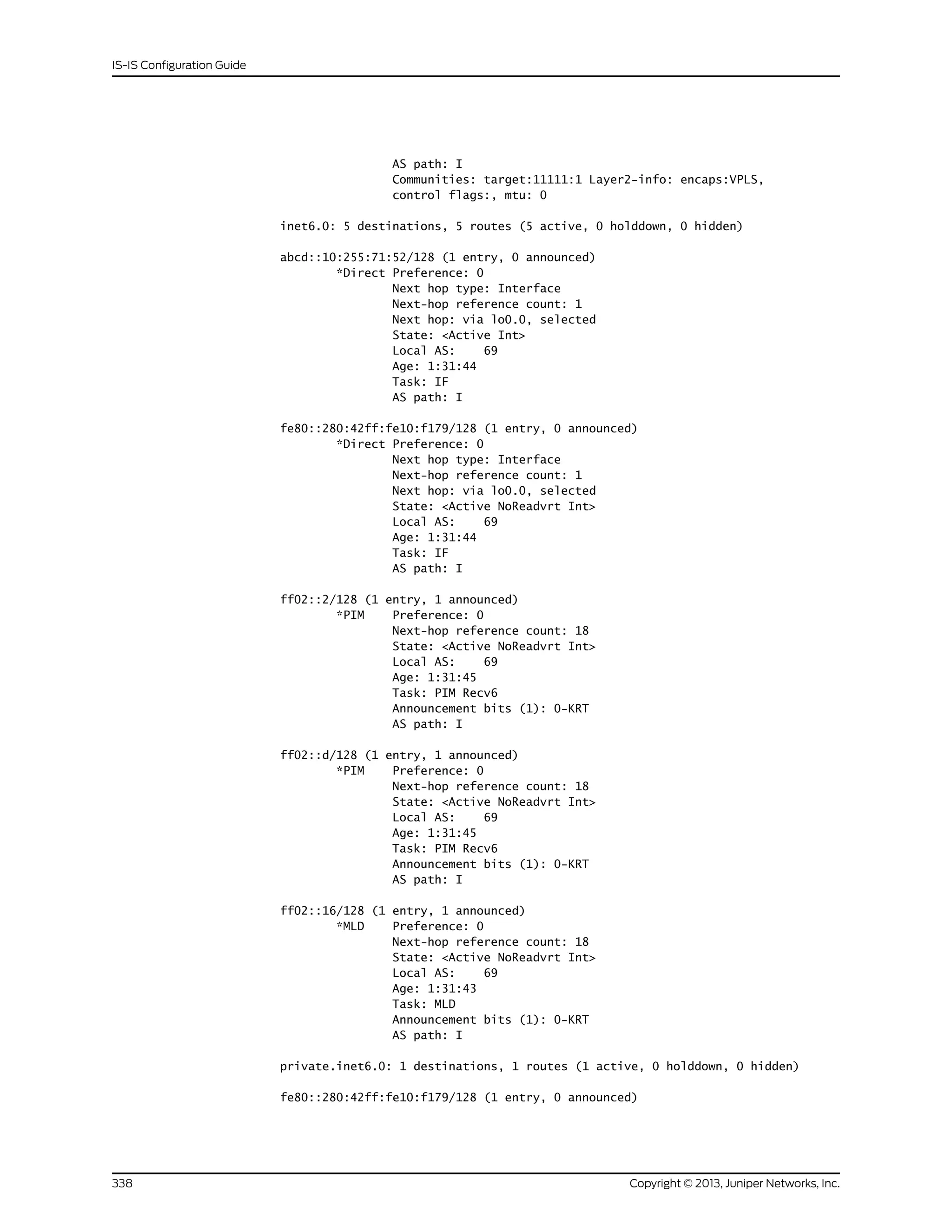
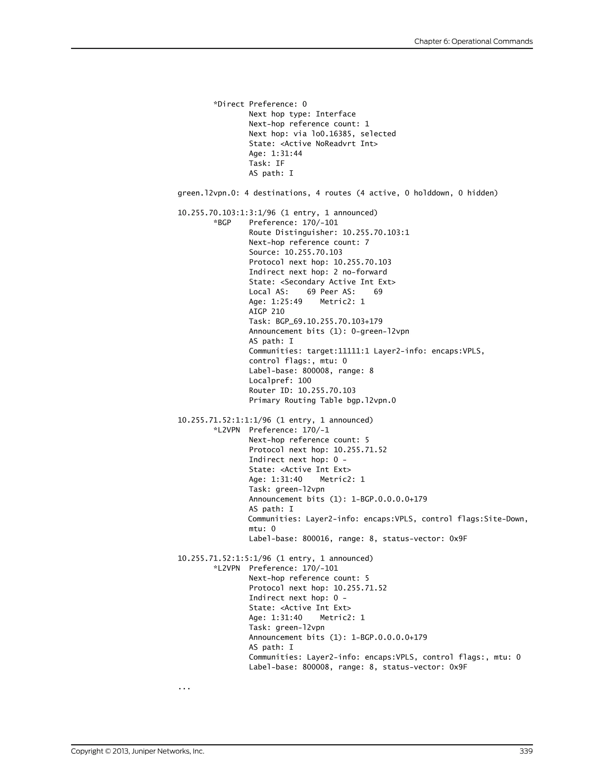
![l2circuit.0: 2 destinations, 2 routes (2 active, 0 holddown, 0 hidden)
10.245.255.63:CtrlWord:4:3:Local/96 (1 entry, 1 announced)
*L2CKT Preference: 7
Next hop: via so-1/1/2.0 weight 1, selected
Label-switched-path my-lsp
Label operation: Push 100000[0]
Protocol next hop: 10.245.255.63 Indirect next hop: 86af000 296
State: <Active Int>
Local AS: 99
Age: 10:21
Task: l2 circuit
Announcement bits (1): 0-LDP
AS path: I
VC Label 100000, MTU 1500, VLAN ID 512
showroutedetail(with
BGP Multipath)
user@host> show route detail
10.1.1.8/30 (2 entries, 1 announced)
*BGP Preference: 170/-101
Next hop type: Router, Next hop index: 262142
Address: 0x901a010
Next-hop reference count: 2
Source: 10.1.1.2
Next hop: 10.1.1.2 via ge-0/3/0.1, selected
Next hop: 10.1.1.6 via ge-0/3/0.5
State: <Active Ext>
Local AS: 1 Peer AS: 2
Age: 5:04:43
Task: BGP_2.10.1.1.2+59955
Announcement bits (1): 0-KRT
AS path: 2 I
Accepted Multipath
Localpref: 100
Router ID: 1.1.1.2
BGP Preference: 170/-101
Next hop type: Router, Next hop index: 678
Address: 0x8f97520
Next-hop reference count: 9
Source: 10.1.1.6
Next hop: 10.1.1.6 via ge-0/3/0.5, selected
State: <NotBest Ext>
Inactive reason: Not Best in its group - Active preferred
Local AS: 1 Peer AS: 2
Age: 5:04:43
Task: BGP_2.10.1.1.6+58198
AS path: 2 I
Accepted MultipathContrib
Localpref: 100
Router ID: 1.1.1.3
Copyright © 2013, Juniper Networks, Inc.340
IS-IS Configuration Guide](https://image.slidesharecdn.com/config-guide-routing-is-is-151104131021-lva1-app6891/75/Juniper-MX-Config-guide-routing-is-is-360-2048.jpg)
![Sample Output
show route exact user@host> show route exact 207.17.136.0/24
inet.0: 24 destinations, 25 routes (23 active, 0 holddown, 1 hidden)
Restart Complete
+ = Active Route, - = Last Active, * = Both
207.17.136.0/24 *[Static/5] 2d 03:30:22
> to 192.168.71.254 via fxp0.0
showrouteexactdetail user@host> show route exact 207.17.136.0/24 detail
inet.0: 24 destinations, 25 routes (23 active, 0 holddown, 1 hidden)
Restart Complete
207.17.136.0/24 (1 entry, 1 announced)
*Static Preference: 5
Next-hop reference count: 29
Next hop: 192.168.71.254 via fxp0.0, selected
State: <Active NoReadvrt Int Ext>
Local AS: 69
Age: 2d 3:30:26
Task: RT
Announcement bits (2): 0-KRT 3-Resolve tree 2
AS path: I
show route exact
extensive
user@host> show route exact 207.17.136.0/24 extensive
inet.0: 22 destinations, 23 routes (21 active, 0 holddown, 1 hidden)
207.17.136.0/24 (1 entry, 1 announced)
TSI:
KRT in-kernel 207.17.136.0/24 -> {192.168.71.254}
*Static Preference: 5
Next-hop reference count: 29
Next hop: 192.168.71.254 via fxp0.0, selected
State: <Active NoReadvrt Int Ext>
Local AS: 69
Age: 1:25:18
Task: RT
Announcement bits (2): 0-KRT 3-Resolve tree 2
AS path: I
show route exact terse user@host> show route exact 207.17.136.0/24 terse
inet.0: 22 destinations, 23 routes (21 active, 0 holddown, 1 hidden)
+ = Active Route, - = Last Active, * = Both
A Destination P Prf Metric 1 Metric 2 Next hop AS path
* 207.17.136.0/24 S 5 >192.168.71.254
Copyright © 2013, Juniper Networks, Inc.342
IS-IS Configuration Guide](https://image.slidesharecdn.com/config-guide-routing-is-is-151104131021-lva1-app6891/75/Juniper-MX-Config-guide-routing-is-is-362-2048.jpg)
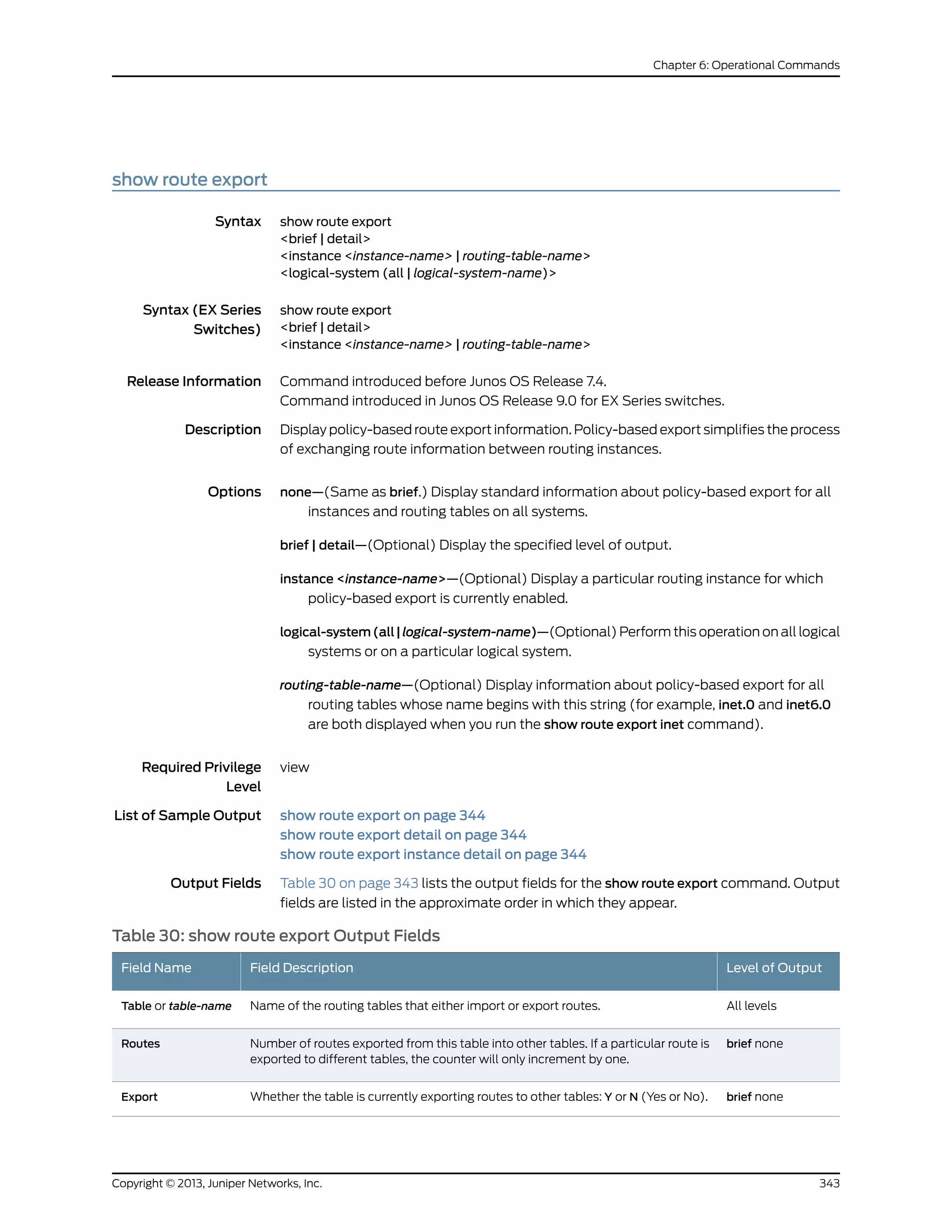
![Table 30: show route export Output Fields (continued)
Level of OutputField DescriptionField Name
detailTables currently importing routes from the originator table. (Not displayed for
tables that are not exporting any routes.)
Import
detail(instance keyword only) Flags for this feature on this instance:
• config auto-policy—The policy was deduced from the configured IGP export
policies.
• cleanup—Configuration information for this instance is no longer valid.
• config—The instance was explicitly configured.
Flags
detail(instance keyword only) Configured option displays the type of routing tables the
feature handles:
• unicast—Indicates instance.inet.0.
• multicast—Indicates instance.inet.2.
• unicast multicast—Indicates instance.inet.0 and instance.inet.2.
Options
detail(instance keyword only) Policy that routeexport uses to construct the import-export
matrix. Not displayed if the instance type is vrf.
Import policy
detail(instance keyword only) Name of the routing instance.Instance
detail(instance keyword only) Type of routing instance: forwarding, non-forwarding, or
vrf.
Type
Sample Output
show route export user@host> show route export
Table Export Routes
inet.0 N 0
black.inet.0 Y 3
red.inet.0 Y 4
show route export
detail
user@host> show route export detail
inet.0 Routes: 0
black.inet.0 Routes: 3
Import: [ inet.0 ]
red.inet.0 Routes: 4
Import: [ inet.0 ]
show route export
instance detail
user@host> show route export instance detail
Instance: master Type: forwarding
Flags: <config auto-policy> Options: <unicast multicast>
Import policy: [ (ospf-master-from-red || isis-master-from-black) ]
Instance: black Type: non-forwarding
Instance: red Type: non-forwarding
Copyright © 2013, Juniper Networks, Inc.344
IS-IS Configuration Guide](https://image.slidesharecdn.com/config-guide-routing-is-is-151104131021-lva1-app6891/75/Juniper-MX-Config-guide-routing-is-is-364-2048.jpg)
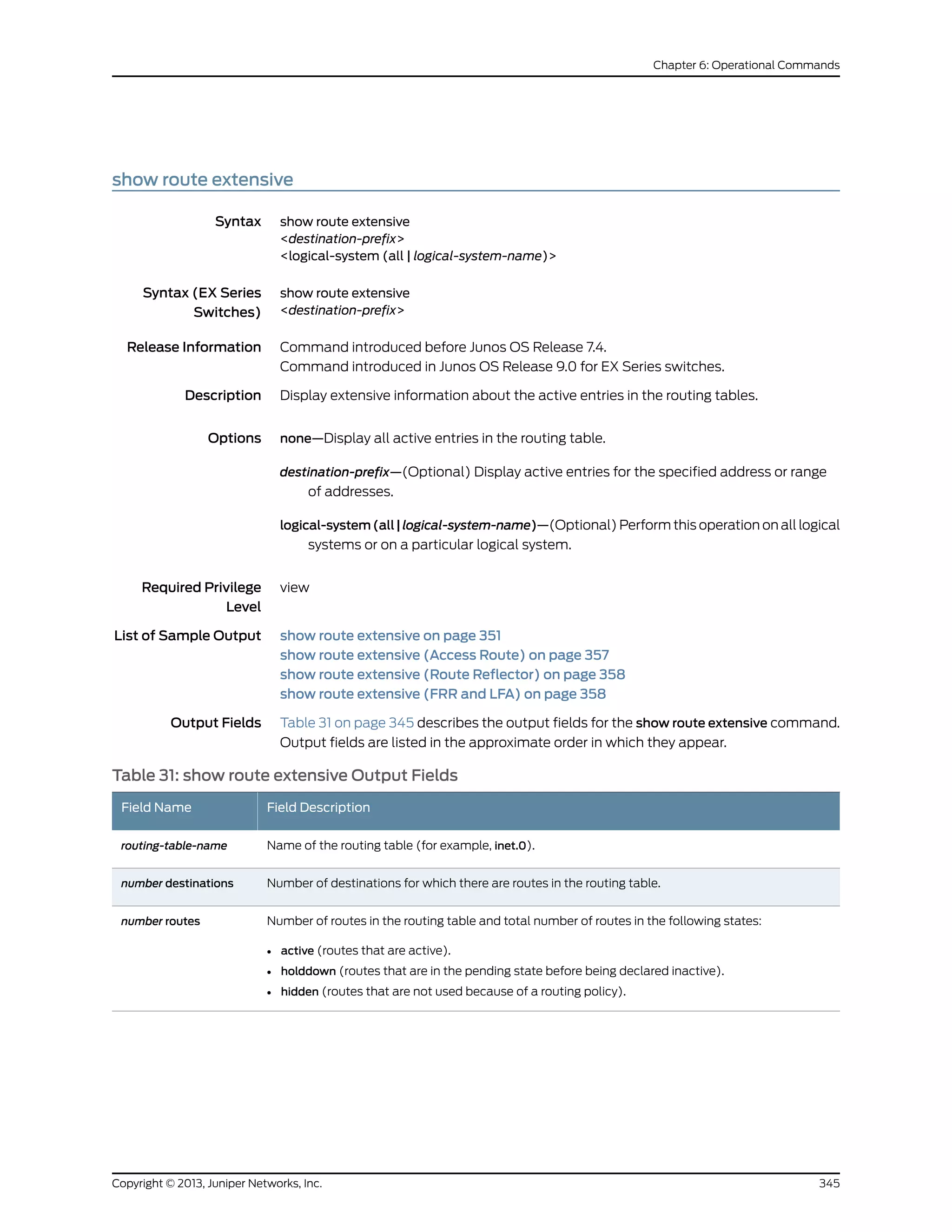
![Table 31: show route extensive Output Fields (continued)
Field DescriptionField Name
Route destination (for example:10.0.0.1/24). The entry value is the number of route for this destination,
and the announced value is the number of routes being announced for this destination. Sometimes
the route destination is presented in another format, such as:
• MPLS-label (for example, 80001 ).
• interface-name (for example, ge-1/0/2 ).
• neighbor-address:control-word-status:encapsulationtype:vc-id:source (Layer 2 circuit only; for example,
10.1.1.195:NoCtrlWord:1:1:Local/96).
• neighbor-address—Address of the neighbor.
• control-word-status—Whether the use of the control word has been negotiated for this virtual
circuit: NoCtrlWord or CtrlWord.
• encapsulation type—Type of encapsulation, represented by a number: (1) Frame Relay DLCI, (2)
ATM AAL5 VCC transport, (3) ATM transparent cell transport, (4) Ethernet, (5) VLAN Ethernet,
(6) HDLC, (7) PPP, (8) ATM VCC cell transport, (10) ATM VPC cell transport.
• vc-id—Virtual circuit identifier.
• source—Source of the advertisement: Local or Remote.
route-destination
(entry, announced)
Protocol header information.TSI
(Next-to-the-last-hop routing device for MPLS only) Depth of the MPLS label stack, where the
label-popping operation is needed to remove one or more labels from the top of the stack. A pair of
routes is displayed, because the pop operation is performed only when the stack depth is two or more
labels.
• S=0 route indicates that a packet with an incoming label stack depth of two or more exits this router
with one fewer label (the label-popping operation is performed).
• If there is no S= information, the route is a normal MPLS route, which has a stack depth of 1 (the
label-popping operation is not performed).
label stacking
Protocol from which the route was learned and the preference value for the route.
• +—A plus sign indicates the active route, which is the route installed from the routing table into the
forwarding table.
• - —A hyphen indicates the last active route.
• *—An asterisk indicates that the route is both the active and the last active route. An asterisk before
a to line indicates the best subpath to the route.
In every routing metric except for the BGP LocalPref attribute, a lesser value is preferred. In order to
use common comparison routines, Junos OS stores the 1's complement of the LocalPref value in the
Preference2 field. For example, if the LocalPref value for Route 1 is 100, the Preference2 value is -101.
If the LocalPref value for Route 2 is 155, the Preference2 value is -156. Route 2 is preferred because it
has a higher LocalPref value and a lower Preference2 value.
[protocol, preference]
(IS-IS only). In IS-IS, a single autonomous system (AS) can be divided into smaller groups called
areas. Routing between areas is organized hierarchically, allowing a domain to be administratively
divided into smaller areas. This organization is accomplished by configuring Level 1 and Level 2
intermediate systems. Level 1 systems route within an area. When the destination is outside an area,
they route toward a Level 2 system. Level 2 intermediate systems route between areas and toward
other ASs.
Level
IP subnet augmented with a 64-bit prefix.Route Distinguisher
Copyright © 2013, Juniper Networks, Inc.346
IS-IS Configuration Guide](https://image.slidesharecdn.com/config-guide-routing-is-is-151104131021-lva1-app6891/75/Juniper-MX-Config-guide-routing-is-is-366-2048.jpg)
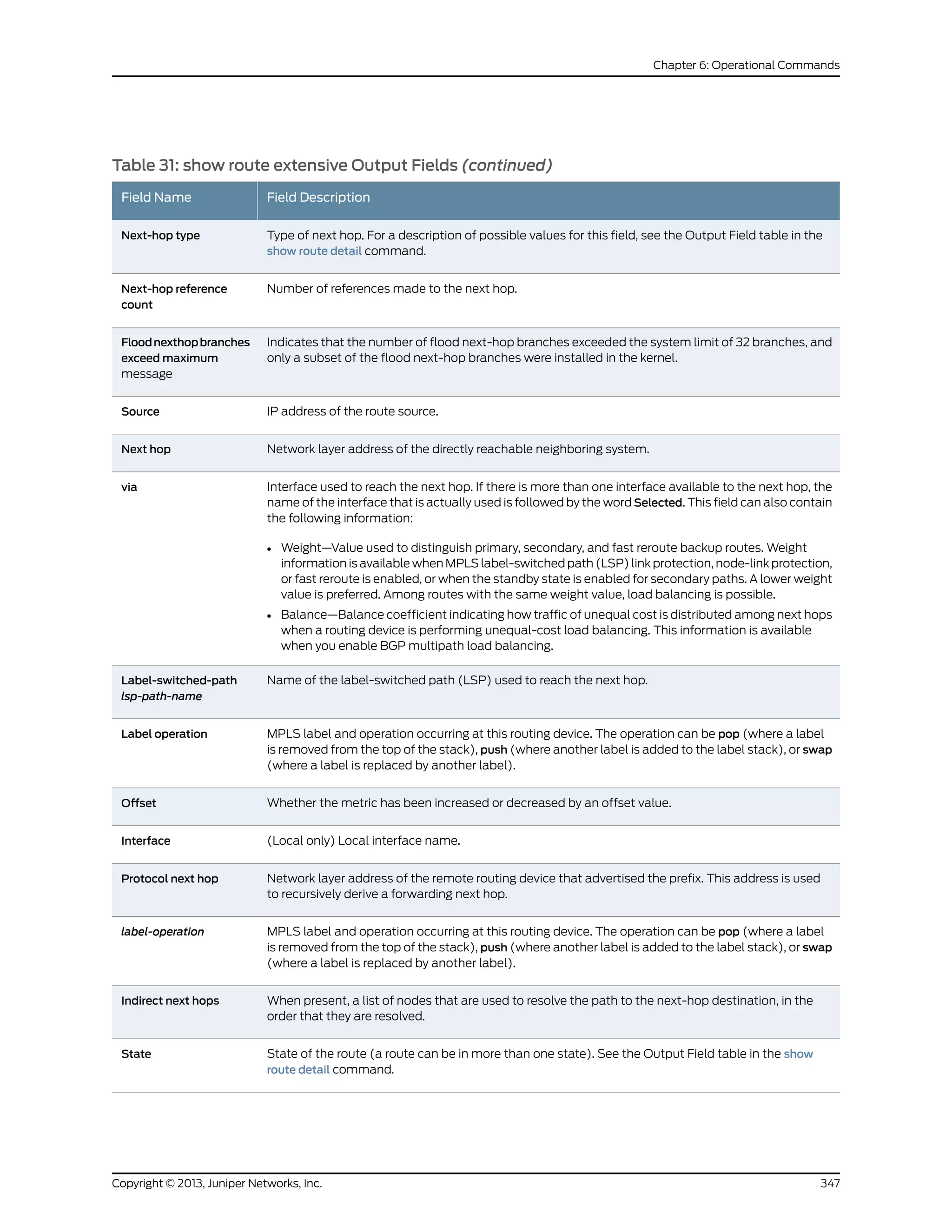
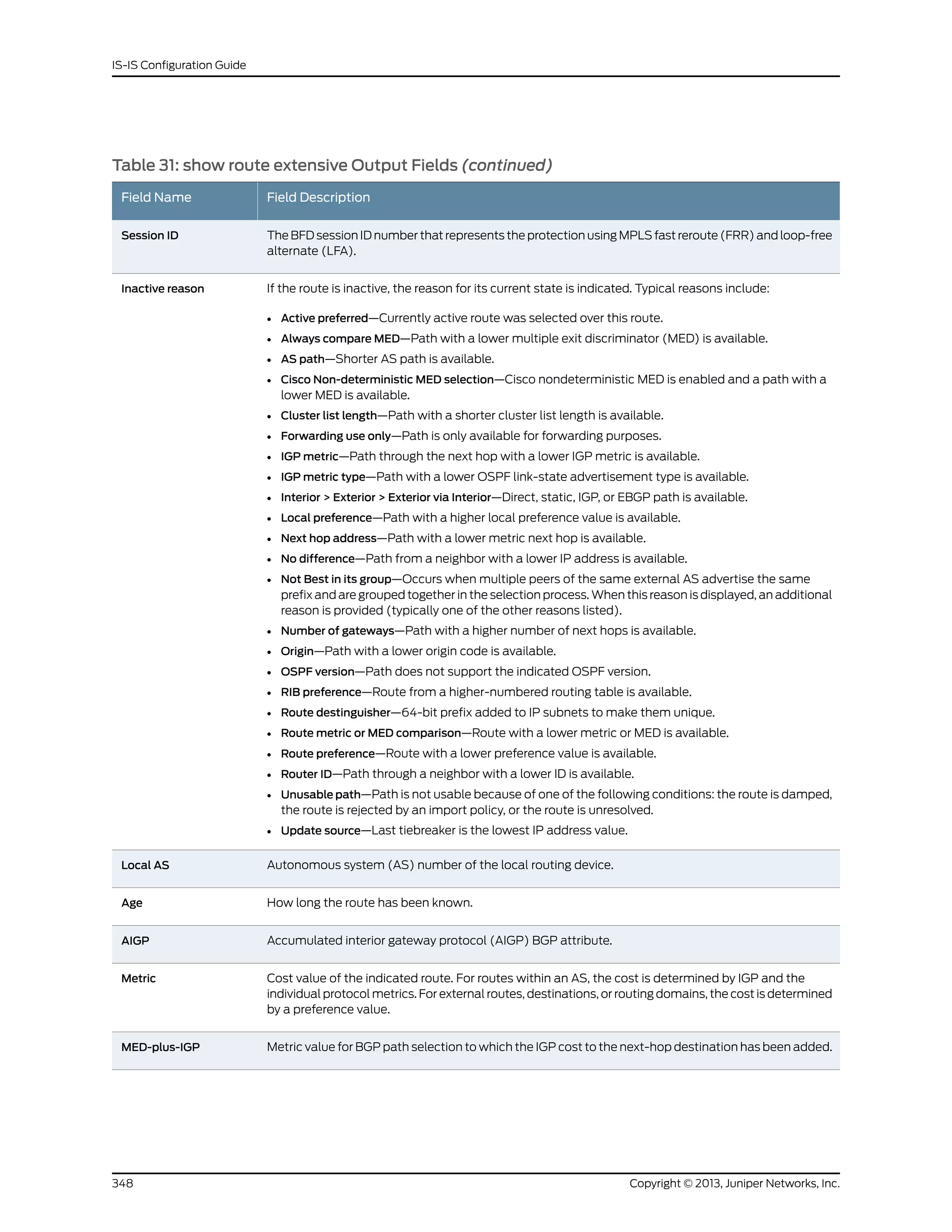
![Table 31: show route extensive Output Fields (continued)
Field DescriptionField Name
For MPLS LSPs, state of the TTL propagation attribute. Can be enabled or disabled for all
RSVP-signaled and LDP-signaled LSPs or for specific VRF routing instances.
For sample output, see show route table.
TTL-Action
Name of the protocol that has added the route.Task
List of protocols that announce this route. n-Resolve inet indicates that the route is used for route
resolution for next hops found in the routing table. n is an index used by Juniper Networks customer
support only.
Announcement bits
AS path through which the route was learned. The letters at the end of the AS path indicate the path
origin, providing an indication of the state of the route at the point at which the AS path originated:
• I—IGP.
• E—EGP.
• Recorded—The AS path is recorded by the sample process (sampled).
• ?—Incomplete; typically, the AS path was aggregated.
When AS path numbers are included in the route, the format is as follows:
• [ ]—Brackets enclose the local AS number associated with the AS path if more than one AS number
is configured on the routing device, or if AS path prepending is configured.
• { }—Braces enclose AS sets, which are groups of AS numbers in which the order does not matter.
A set commonly results from route aggregation. The numbers in each AS set are displayed in
ascending order.
• ( )—Parentheses enclose a confederation.
• ( [ ] )—Parentheses and brackets enclose a confederation set.
NOTE: In Junos OS Release 10.3 and later, the AS path field displays an unrecognized attribute and
associated hexadecimal value if BGP receives attribute 128 (attribute set) and you have not configured
an independent domain in any routing instance.
AS path
(For route reflected output only) Originator ID attribute set by the route reflector.AS path: I <Originator>
MPLS label assigned to the Layer 2 circuit virtual connection.VC Label
Maximum transmission unit (MTU) of the Layer 2 circuit.MTU
VLAN identifier of the Layer 2 circuit.VLAN ID
(For route reflected output only) Cluster ID sent by the route reflector.Cluster list
(For route reflected output only) Address of router that originally sent the route to the route reflector.Originator ID
Forwarding equivalent class (FEC) bound to this route. Applicable only to routes installed by LDP.Prefixes bound to route
Community path attribute for the route. See the Output Field table in the show route detail command
for all possible values for this field.
Communities
349Copyright © 2013, Juniper Networks, Inc.
Chapter 6: Operational Commands](https://image.slidesharecdn.com/config-guide-routing-is-is-151104131021-lva1-app6891/75/Juniper-MX-Config-guide-routing-is-is-369-2048.jpg)
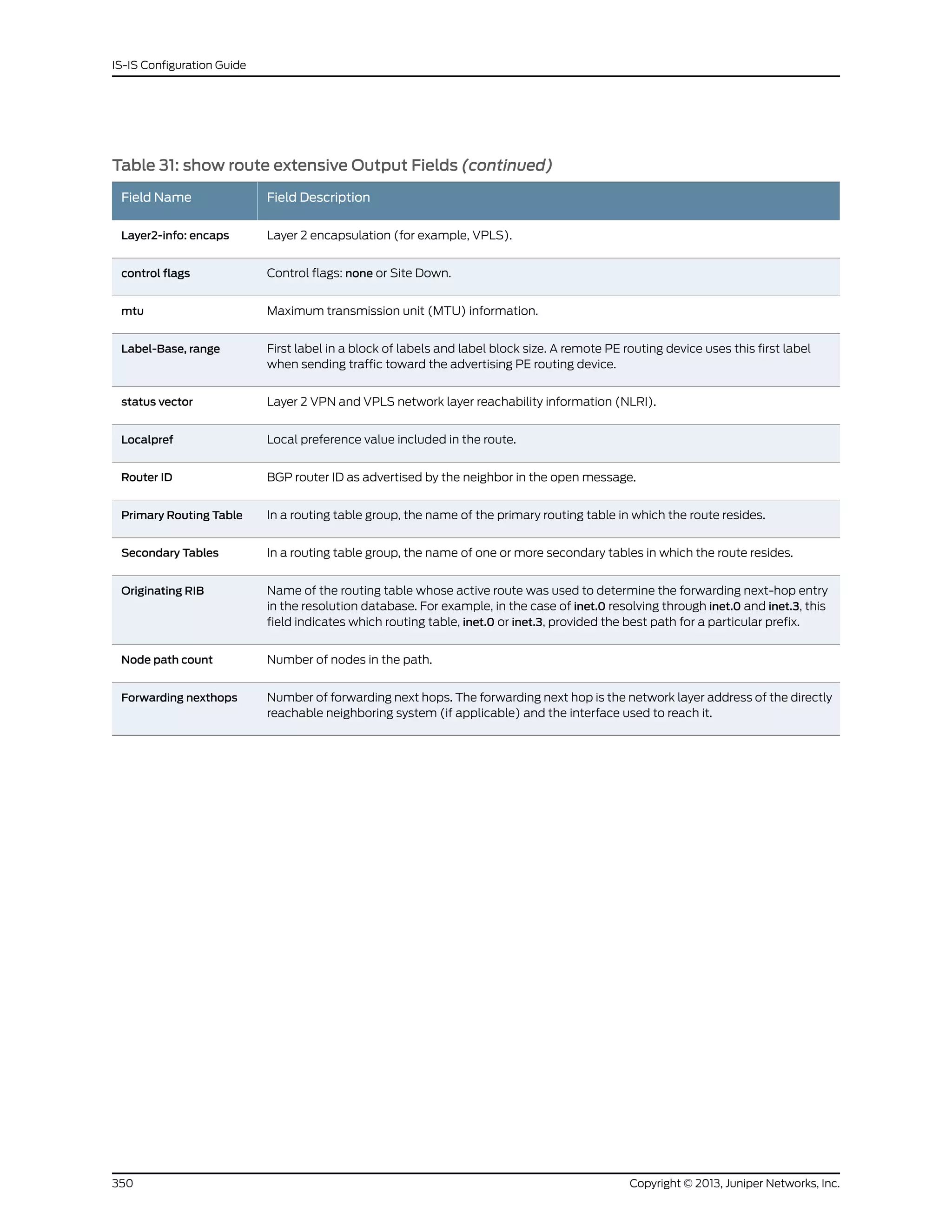
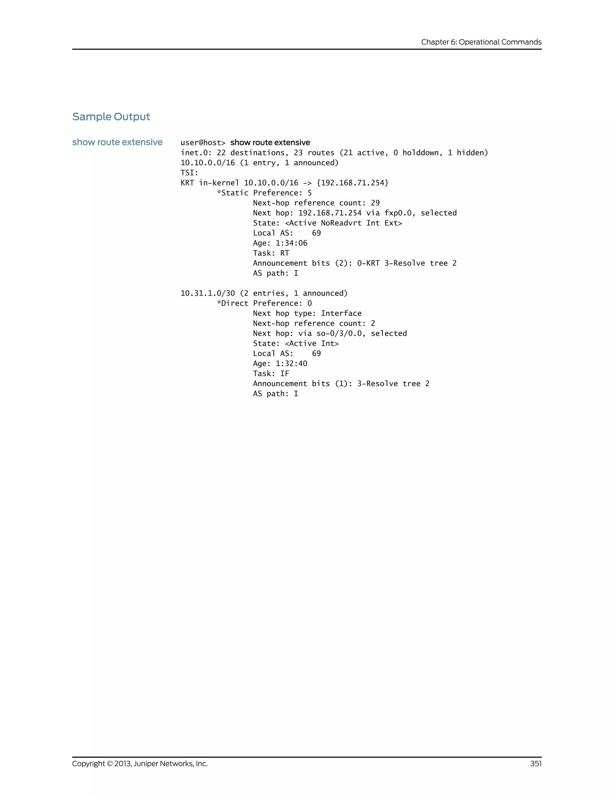
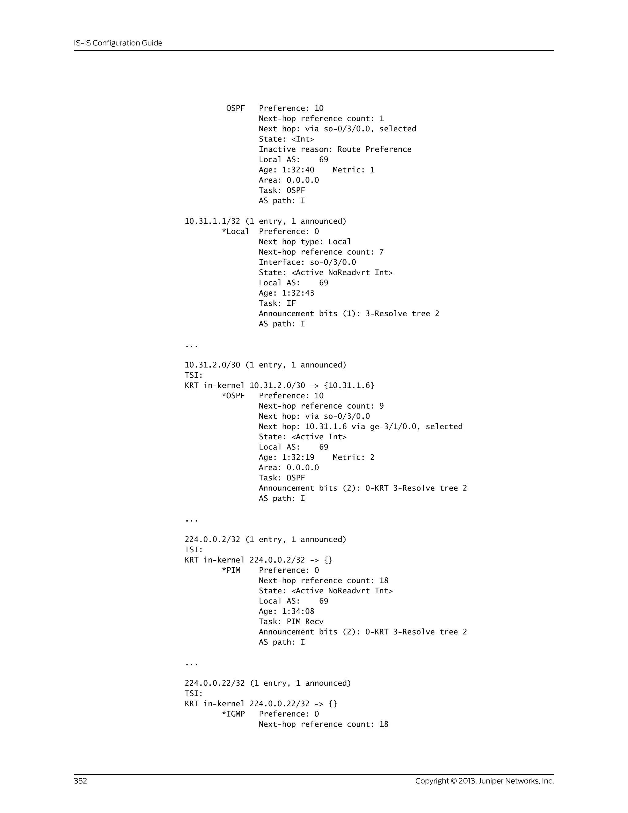
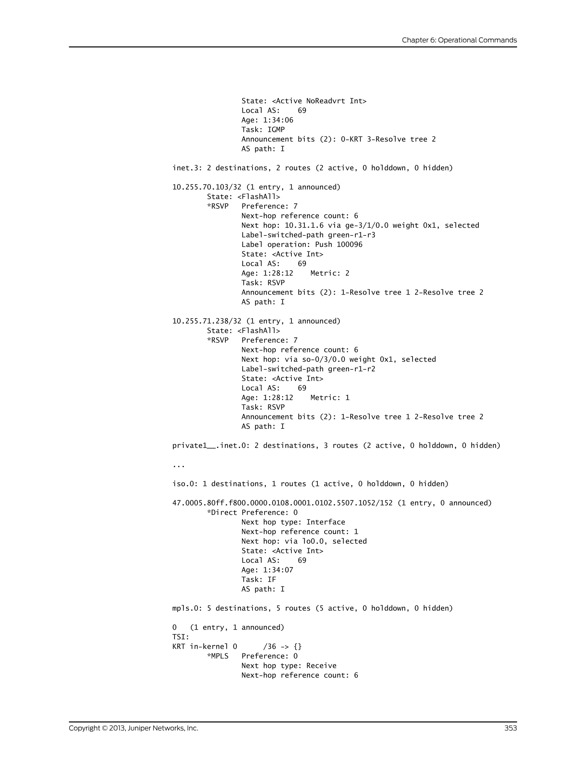
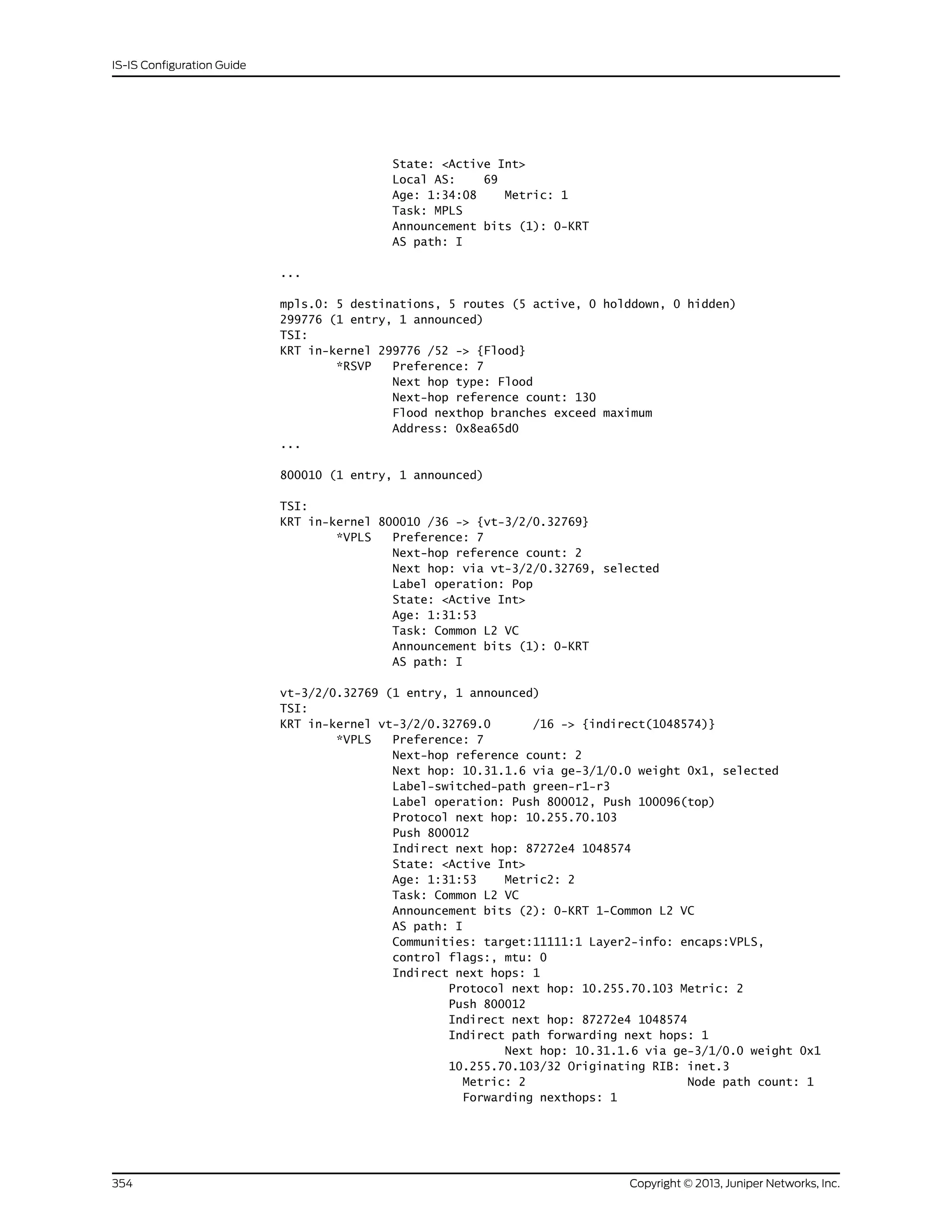
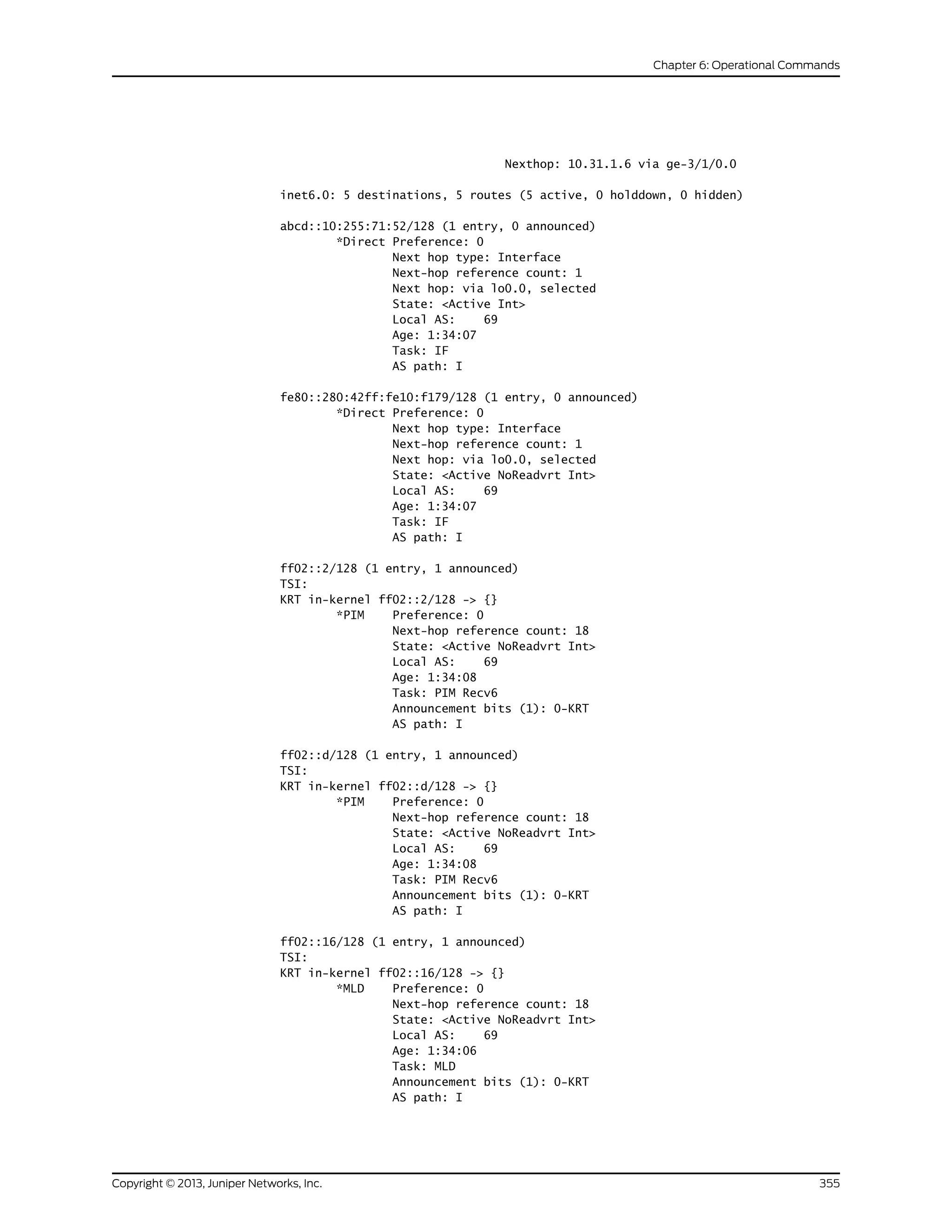
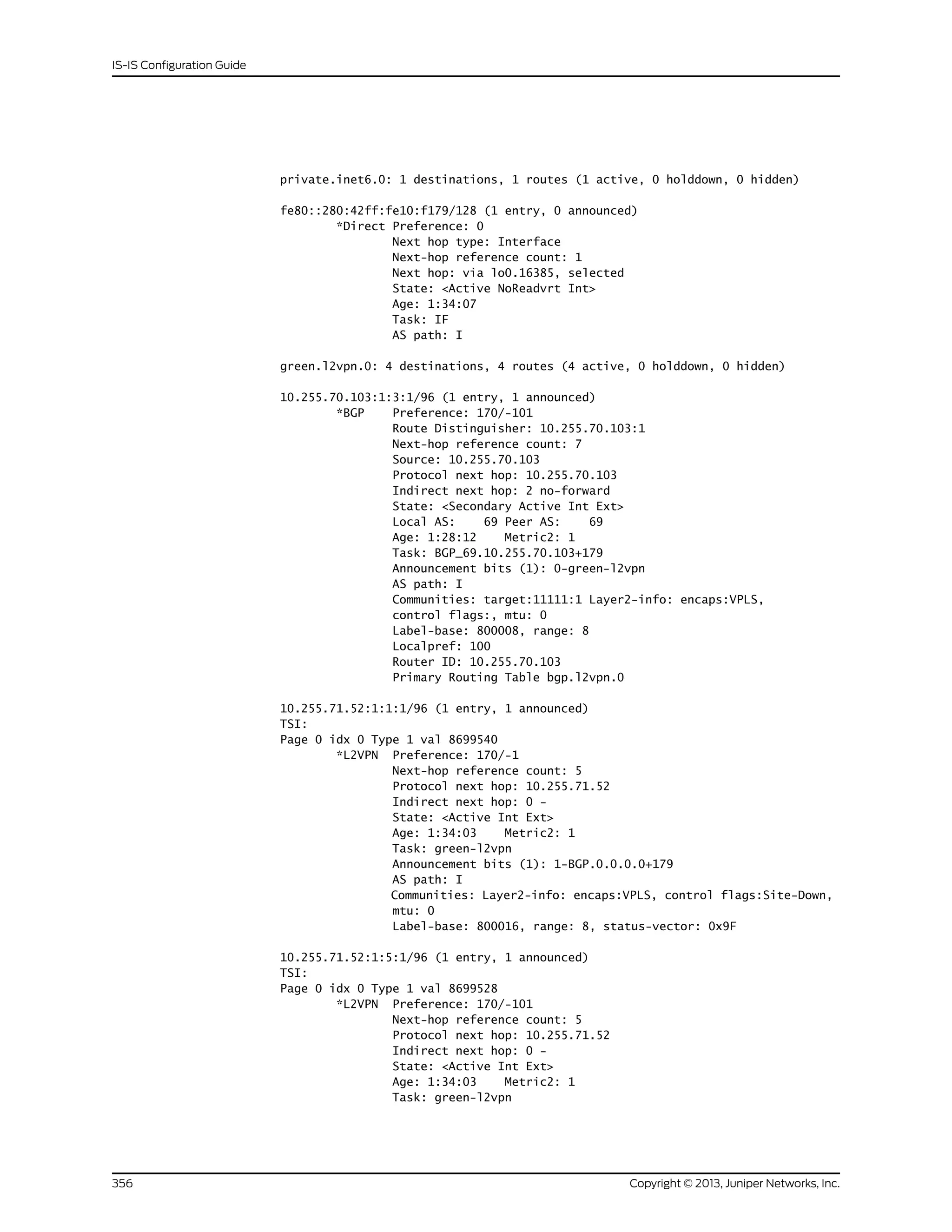
![Announcement bits (1): 1-BGP.0.0.0.0+179
AS path: I
Communities: Layer2-info: encaps:VPLS, control flags:, mtu: 0
Label-base: 800008, range: 8, status-vector: 0x9F
...
l2circuit.0: 2 destinations, 2 routes (2 active, 0 holddown, 0 hidden)
TSI:
10.245.255.63:CtrlWord:4:3:Local/96 (1 entry, 1 announced)
*L2CKT Preference: 7
Next hop: via so-1/1/2.0 weight 1, selected
Label-switched-path my-lsp
Label operation: Push 100000[0]
Protocol next hop: 10.245.255.63 Indirect next hop: 86af000 296
State: <Active Int>
Local AS: 99
Age: 10:21
Task: l2 circuit
Announcement bits (1): 0-LDP
AS path: I
VC Label 100000, MTU 1500, VLAN ID 512
55.0.0.0/24 (1 entry, 1 announced)
TSI:
KRT queued (pending) add
55.0.0.0/24 -> {Push 300112}
*BGP Preference: 170/-101
Next hop type: Router
Address: 0x925c208
Next-hop reference count: 2
Source: 10.0.0.9
Next hop: 10.0.0.9 via ge-1/2/0.15, selected
Label operation: Push 300112
Label TTL action: prop-ttl
State: <Active Ext>
Local AS: 7019 Peer AS: 13979
Age: 1w0d 23:06:56
AIGP: 25
Task: BGP_13979.10.0.0.9+56732
Announcement bits (1): 0-KRT
AS path: 13979 7018 I
Accepted
Route Label: 300112
Localpref: 100
Router ID: 10.9.9.1
show route extensive
(Access Route)
user@host> show route 13.160.0.102 extensive
inet.0: 39256 destinations, 39258 routes (39255 active, 0 holddown, 1 hidden)
13.160.0.102/32 (1 entry, 1 announced)
TSI:
KRT in-kernel 13.160.0.102/32 -> {13.160.0.2}
OSPF area : 0.0.0.0, LSA ID : 13.160.0.102, LSA type : Extern
*Access Preference: 13
Next-hop reference count: 78472
Next hop: 13.160.0.2 via fe-0/0/0.0, selected
State: <Active Int>
Age: 12
357Copyright © 2013, Juniper Networks, Inc.
Chapter 6: Operational Commands](https://image.slidesharecdn.com/config-guide-routing-is-is-151104131021-lva1-app6891/75/Juniper-MX-Config-guide-routing-is-is-377-2048.jpg)
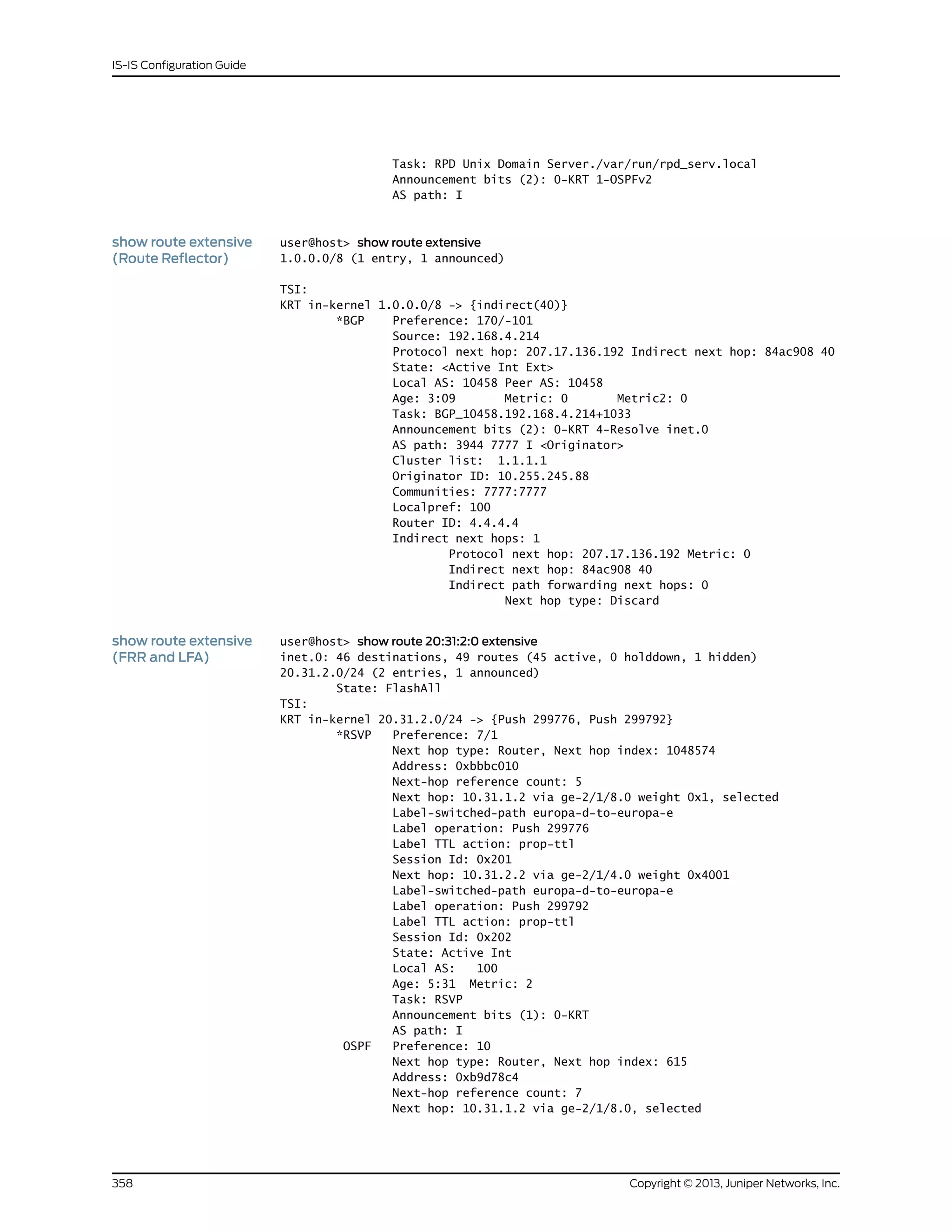

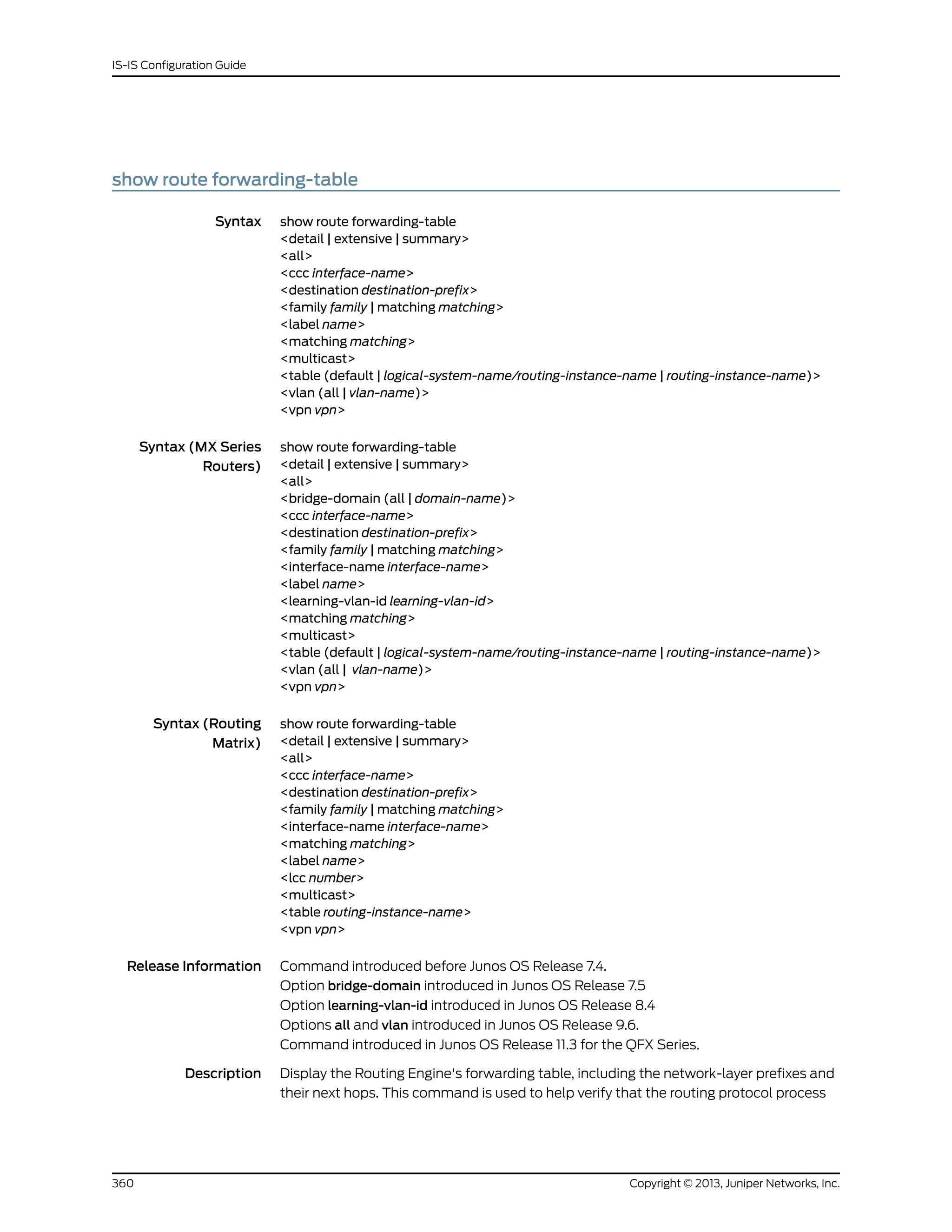
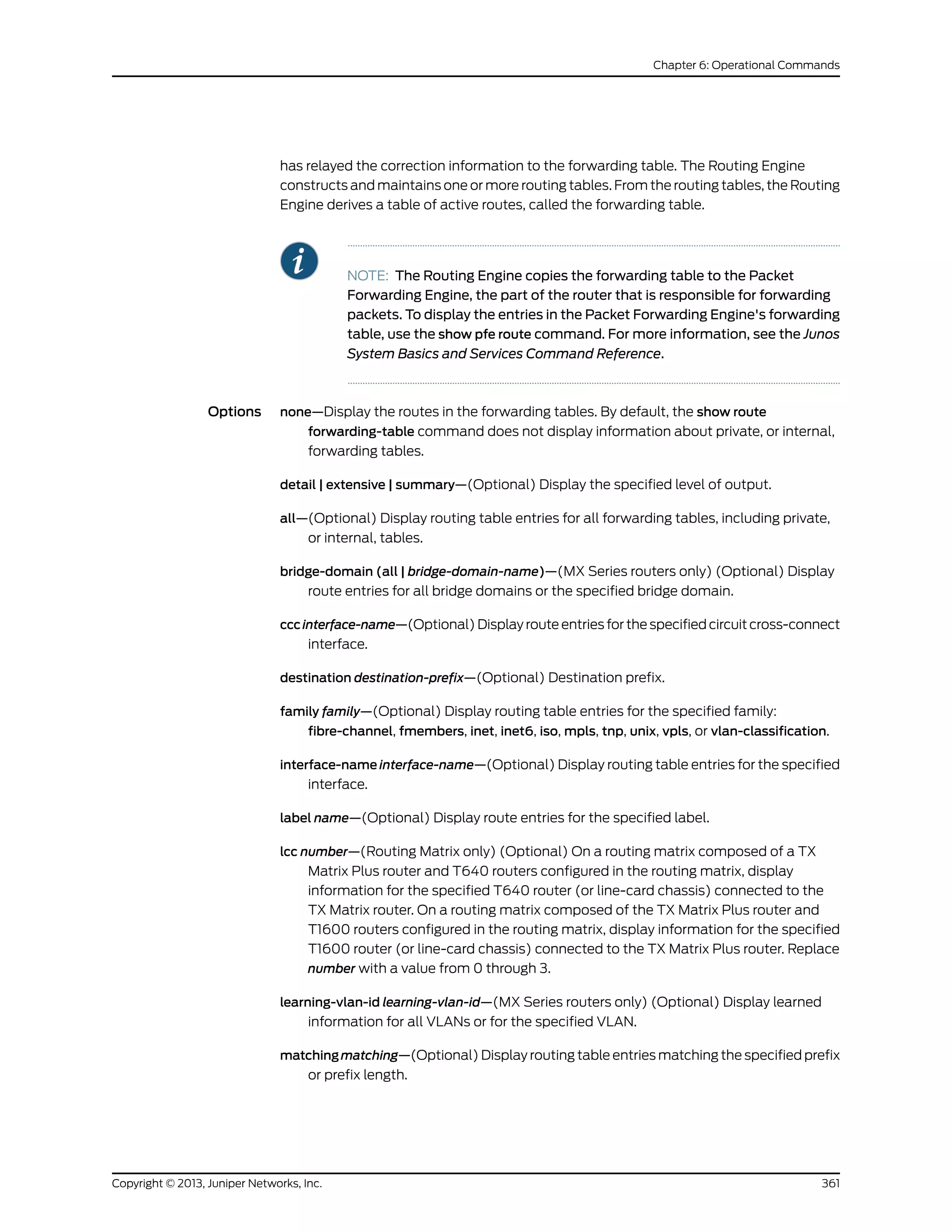
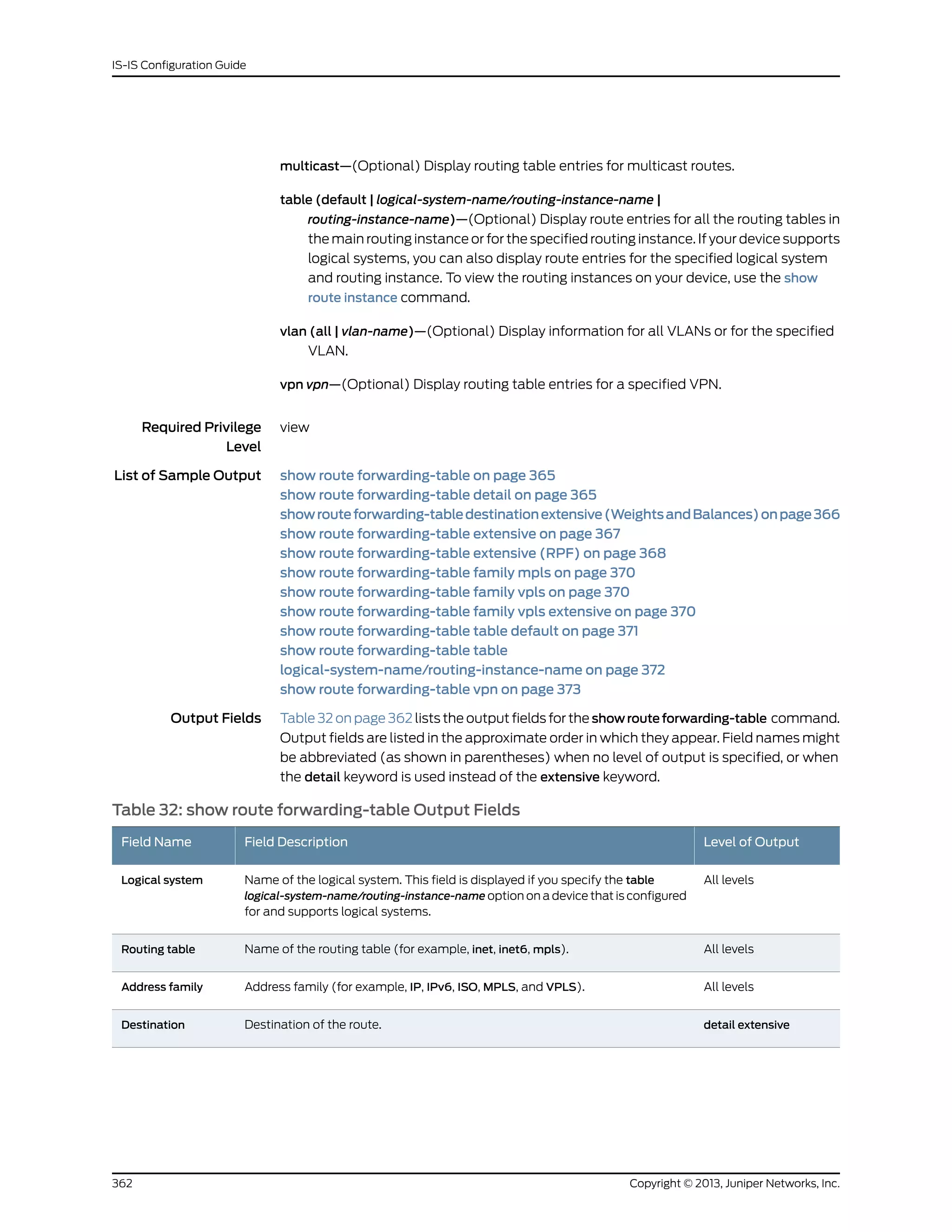
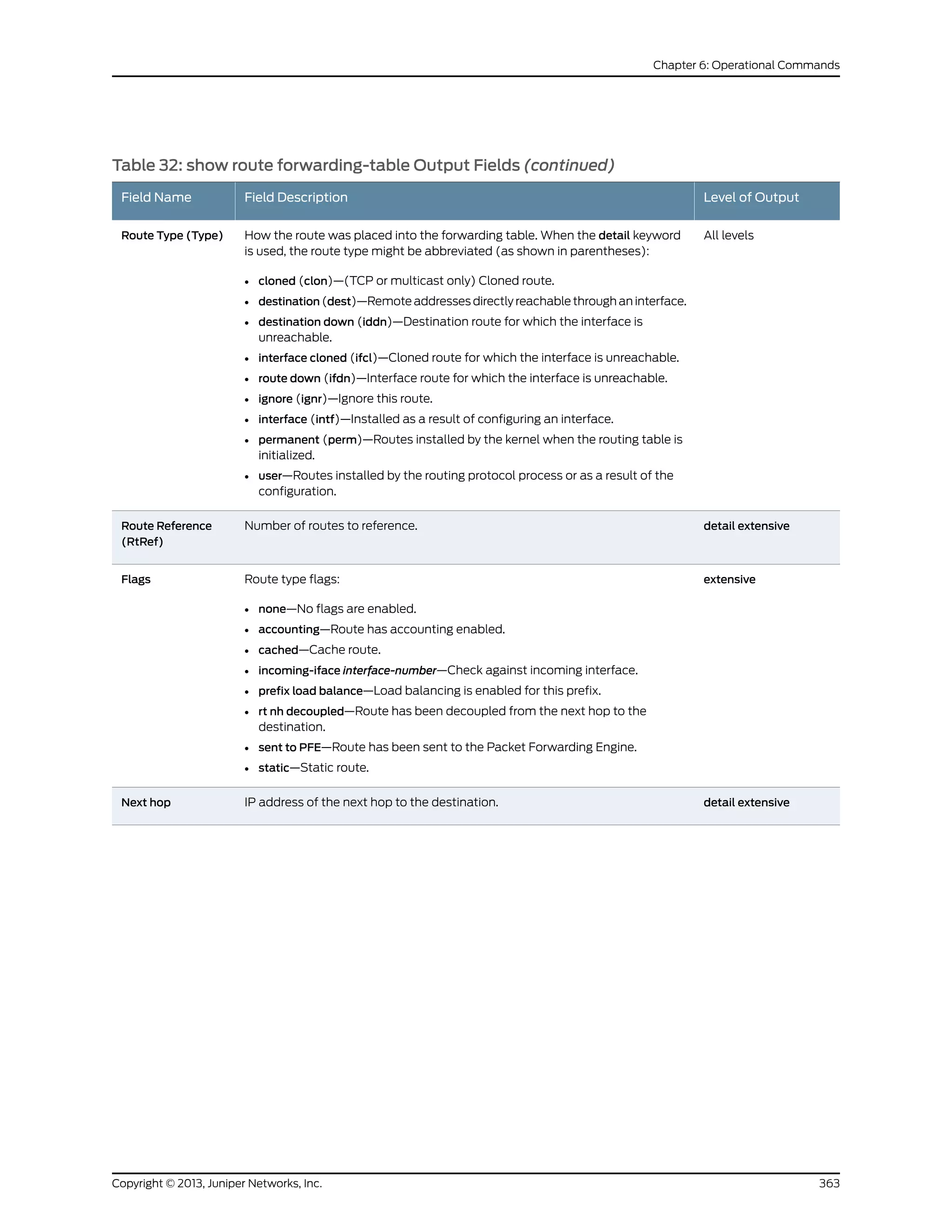
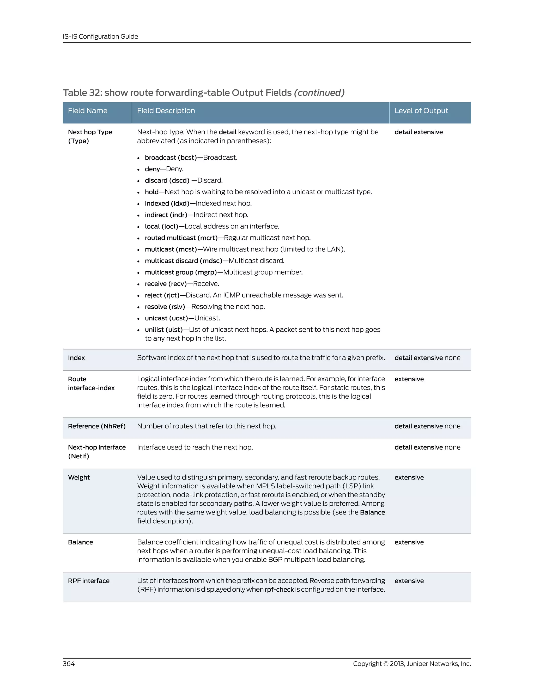
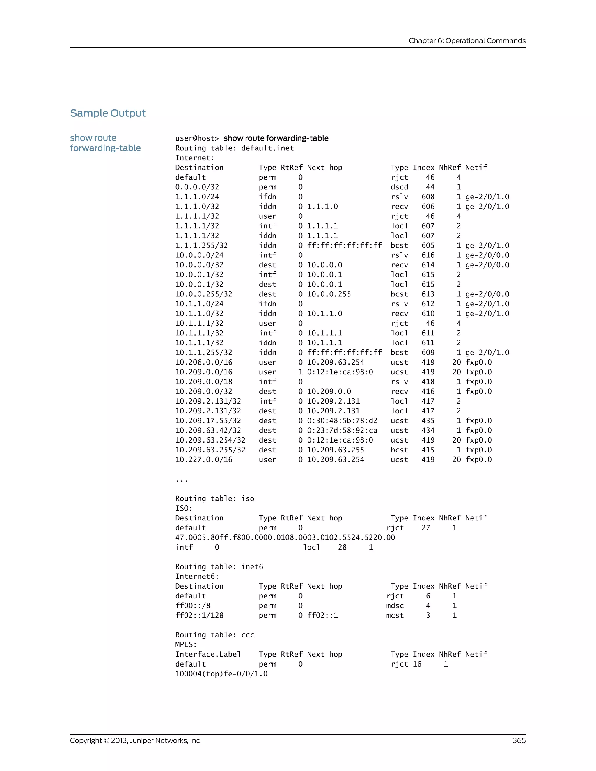
![show route
forwarding-tabledetail
user@host> show route forwarding-table detail
Routing table: inet
Internet:
Destination Type RtRef Next hop Type Index NhRef Netif
default user 2 0:90:69:8e:b1:1b ucst 132 4 fxp0.0
default perm 0 rjct 14 1
10.1.1.0/24 intf 0 ff.3.0.21 ucst 322 1 so-5/3/0.0
10.1.1.0/32 dest 0 10.1.1.0 recv 324 1 so-5/3/0.0
10.1.1.1/32 intf 0 10.1.1.1 locl 321 1
10.1.1.255/32 dest 0 10.1.1.255 bcst 323 1 so-5/3/0.0
10.21.21.0/24 intf 0 ff.3.0.21 ucst 326 1 so-5/3/0.0
10.21.21.0/32 dest 0 10.21.21.0 recv 328 1 so-5/3/0.0
10.21.21.1/32 intf 0 10.21.21.1 locl 325 1
10.21.21.255/32 dest 0 10.21.21.255 bcst 327 1 so-5/3/0.0
127.0.0.1/32 intf 0 127.0.0.1 locl 320 1
172.17.28.19/32 clon 1 192.168.4.254 ucst 132 4 fxp0.0
172.17.28.44/32 clon 1 192.168.4.254 ucst 132 4 fxp0.0
...
Routing table: private1__.inet
Internet:
Destination Type RtRef Next hop Type Index NhRef Netif
default perm 0 rjct 46 1
10.0.0.0/8 intf 0 rslv 136 1 fxp1.0
10.0.0.0/32 dest 0 10.0.0.0 recv 134 1 fxp1.0
10.0.0.4/32 intf 0 10.0.0.4 locl 135 2
10.0.0.4/32 dest 0 10.0.0.4 locl 135 2
...
Routing table: iso
ISO:
Destination Type RtRef Next hop Type Index NhRef Netif
default perm 0 rjct 38 1
Routing table: inet6
Internet6:
Destination Type RtRef Next hop Type Index NhRef Netif
default perm 0 rjct 22 1
ff00::/8 perm 0 mdsc 21 1
ff02::1/128 perm 0 ff02::1 mcst 17 1
...
Routing table: mpls
MPLS:
Destination Type RtRef Next hop Type Index NhRef Netif
default perm 0 rjct 28 1
show route
forwarding-table
user@host> show route forwarding-table destination 3.4.2.1 extensive
Routing table: inet [Index 0]
Internet:destination extensive
Copyright © 2013, Juniper Networks, Inc.366
IS-IS Configuration Guide](https://image.slidesharecdn.com/config-guide-routing-is-is-151104131021-lva1-app6891/75/Juniper-MX-Config-guide-routing-is-is-386-2048.jpg)
![Destination: 3.4.2.1/32
Route type: user
(Weights and
Balances)
Route reference: 0 Route interface-index: 0
Flags: sent to PFE
Next-hop type: unilist Index: 262143 Reference: 1
Nexthop: 4.4.4.4
Next-hop type: unicast Index: 335 Reference: 2
Next-hop interface: so-1/1/0.0 Weight: 22 Balance: 3
Nexthop: 145.12.1.2
Next-hop type: unicast Index: 337 Reference: 2
Next-hop interface: so-0/1/2.0 Weight: 33 Balance: 33
show route
forwarding-table
extensive
user@host> show route forwarding-table extensive
Routing table: inet [Index 0]
Internet:
Destination: default
Route type: user
Route reference: 2 Route interface-index: 0
Flags: sent to PFE
Nexthop: 0:90:69:8e:b1:1b
Next-hop type: unicast Index: 132 Reference: 4
Next-hop interface: fxp0.0
Destination: default
Route type: permanent
Route reference: 0 Route interface-index: 0
Flags: none
Next-hop type: reject Index: 14 Reference: 1
Destination: 127.0.0.1/32
Route type: interface
Route reference: 0 Route interface-index: 0
Flags: sent to PFE
Nexthop: 127.0.0.1
Next-hop type: local Index: 320 Reference: 1
...
Routing table: private1__.inet [Index 1]
Internet:
Destination: default
Route type: permanent
Route reference: 0 Route interface-index: 0
Flags: sent to PFE
Next-hop type: reject Index: 46 Reference: 1
Destination: 10.0.0.0/8
Route type: interface
Route reference: 0 Route interface-index: 3
Flags: sent to PFE
Next-hop type: resolve Index: 136 Reference: 1
Next-hop interface: fxp1.0
...
Routing table: iso [Index 0]
ISO:
Destination: default
367Copyright © 2013, Juniper Networks, Inc.
Chapter 6: Operational Commands](https://image.slidesharecdn.com/config-guide-routing-is-is-151104131021-lva1-app6891/75/Juniper-MX-Config-guide-routing-is-is-387-2048.jpg)
![Route type: permanent
Route reference: 0 Route interface-index: 0
Flags: sent to PFE
Next-hop type: reject Index: 38 Reference: 1
Routing table: inet6 [Index 0]
Internet6:
Destination: default
Route type: permanent
Route reference: 0 Route interface-index: 0
Flags: sent to PFE
Next-hop type: reject Index: 22 Reference: 1
Destination: ff00::/8
Route type: permanent
Route reference: 0 Route interface-index: 0
Flags: sent to PFE
Next-hop type: multicast discard Index: 21 Reference: 1
...
Routing table: private1__.inet6 [Index 1]
Internet6:
Destination: default
Route type: permanent
Route reference: 0 Route interface-index: 0
Flags: sent to PFE
Next-hop type: reject Index: 54 Reference: 1
Destination: fe80::2a0:a5ff:fe3d:375/128
Route type: interface
Route reference: 0 Route interface-index: 0
Flags: sent to PFE
Nexthop: fe80::2a0:a5ff:fe3d:375
Next-hop type: local Index: 75 Reference: 1
...
show route
forwarding-table
extensive (RPF)
The next example is based on the following configuration, which enables an RPF check
on all routes that are learned from this interface, including the interface route:
so-1/1/0 {
unit 0 {
family inet {
rpf-check;
address 15.95.1.2/30;
}
}
}
user@host> show route forwarding-table extensive
Routing table: inet [Index 0]
Internet:
...
...
Destination: 15.95.1.3/32
Route type: destination
Route reference: 0 Route interface-index: 67
Copyright © 2013, Juniper Networks, Inc.368
IS-IS Configuration Guide](https://image.slidesharecdn.com/config-guide-routing-is-is-151104131021-lva1-app6891/75/Juniper-MX-Config-guide-routing-is-is-388-2048.jpg)

![show route
forwarding-table
family mpls
user@host> show route forwarding-table family mpls
Routing table: mpls
MPLS:
Destination Type RtRef Next hop Type Index NhRef Netif
default perm 0 rjct 19 1
0 user 0 recv 18 3
1 user 0 recv 18 3
2 user 0 recv 18 3
100000 user 0 10.31.1.6 swap 100001 fe-1/1/0.0
800002 user 0 Pop vt-0/3/0.32770
vt-0/3/0.32770 (VPLS)
user 0 indr 351 4
Push 800000, Push 100002(top)
so-0/0/0.0
show route
forwarding-table
family vpls
user@host> show route forwarding-table family vpls
Routing table: green.vpls
VPLS:
Destination Type RtRef Next hop Type Index NhRef Netif
default dynm 0 flood 353 1
default perm 0 rjct 298 1
fe-0/1/0.0 dynm 0 flood 355 1
00:90:69:0c:20:1f/48 <<<<<Remote CE
dynm 0 indr 351 4
Push 800000, Push 100002(top)
so-0/0/0.0
00:90:69:85:b0:1f/48 <<<<<<Local CE
dynm 0 ucst 354 2 fe-0/1/0.0
show route
forwarding-table
family vpls extensive
user@host> show route forwarding-table family vpls extensive
Routing table: green.vpls [Index 2]
VPLS:
Destination: default
Route type: dynamic
Route reference: 0 Route interface-index: 72
Flags: sent to PFE
Next-hop type: flood Index: 289 Reference: 1
Next-hop type: unicast Index: 291 Reference: 3
Next-hop interface: fe-0/1/3.0
Next-hop type: unicast Index: 290 Reference: 3
Next-hop interface: fe-0/1/2.0
Destination: default
Route type: permanent
Route reference: 0 Route interface-index: 0
Flags: none
Next-hop type: discard Index: 341 Reference: 1
Destination: fe-0/1/2.0
Route type: dynamic
Route reference: 0 Route interface-index: 69
Flags: sent to PFE
Next-hop type: flood Index: 293 Reference: 1
Next-hop type: indirect Index: 363 Reference: 4
Next-hop type: Push 800016
Copyright © 2013, Juniper Networks, Inc.370
IS-IS Configuration Guide](https://image.slidesharecdn.com/config-guide-routing-is-is-151104131021-lva1-app6891/75/Juniper-MX-Config-guide-routing-is-is-390-2048.jpg)
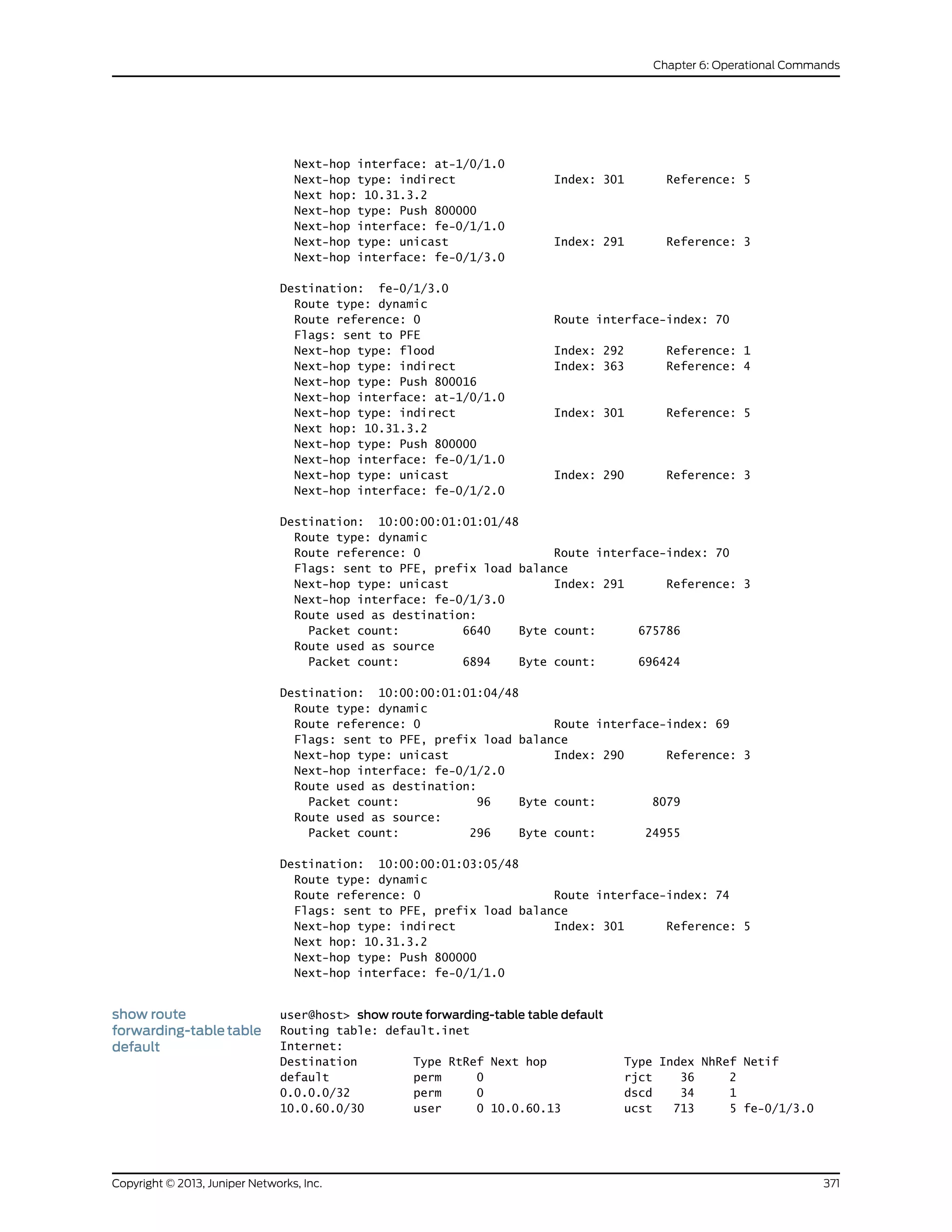
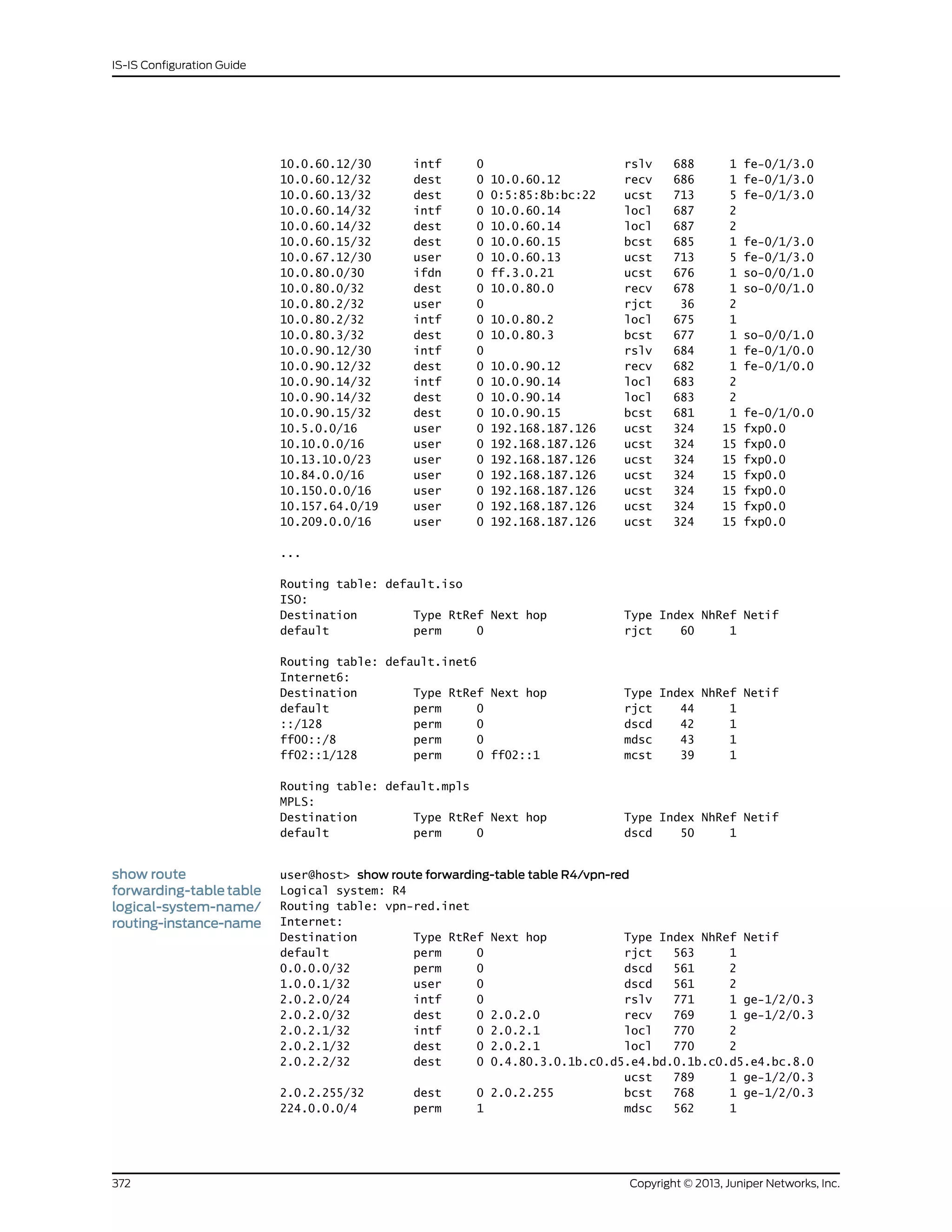
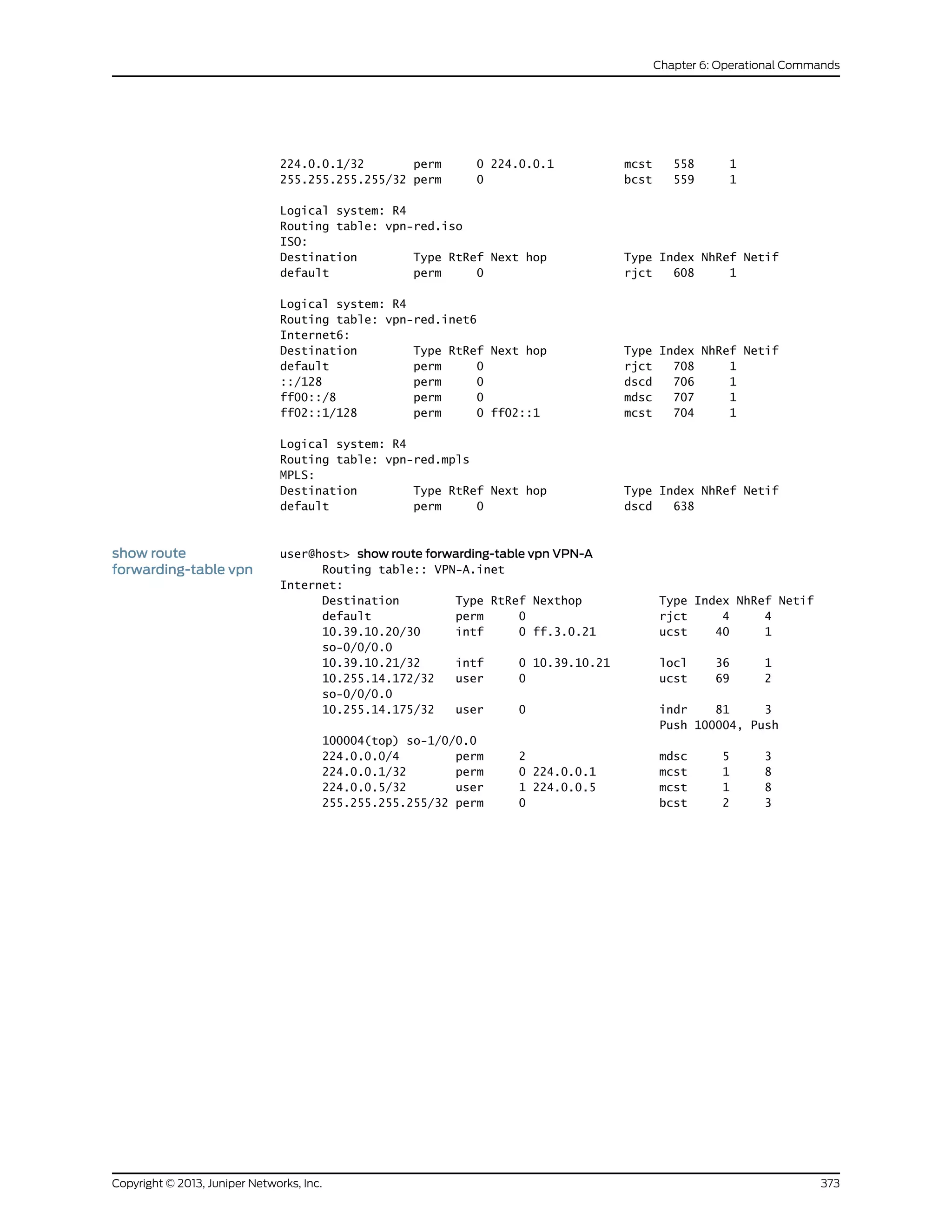
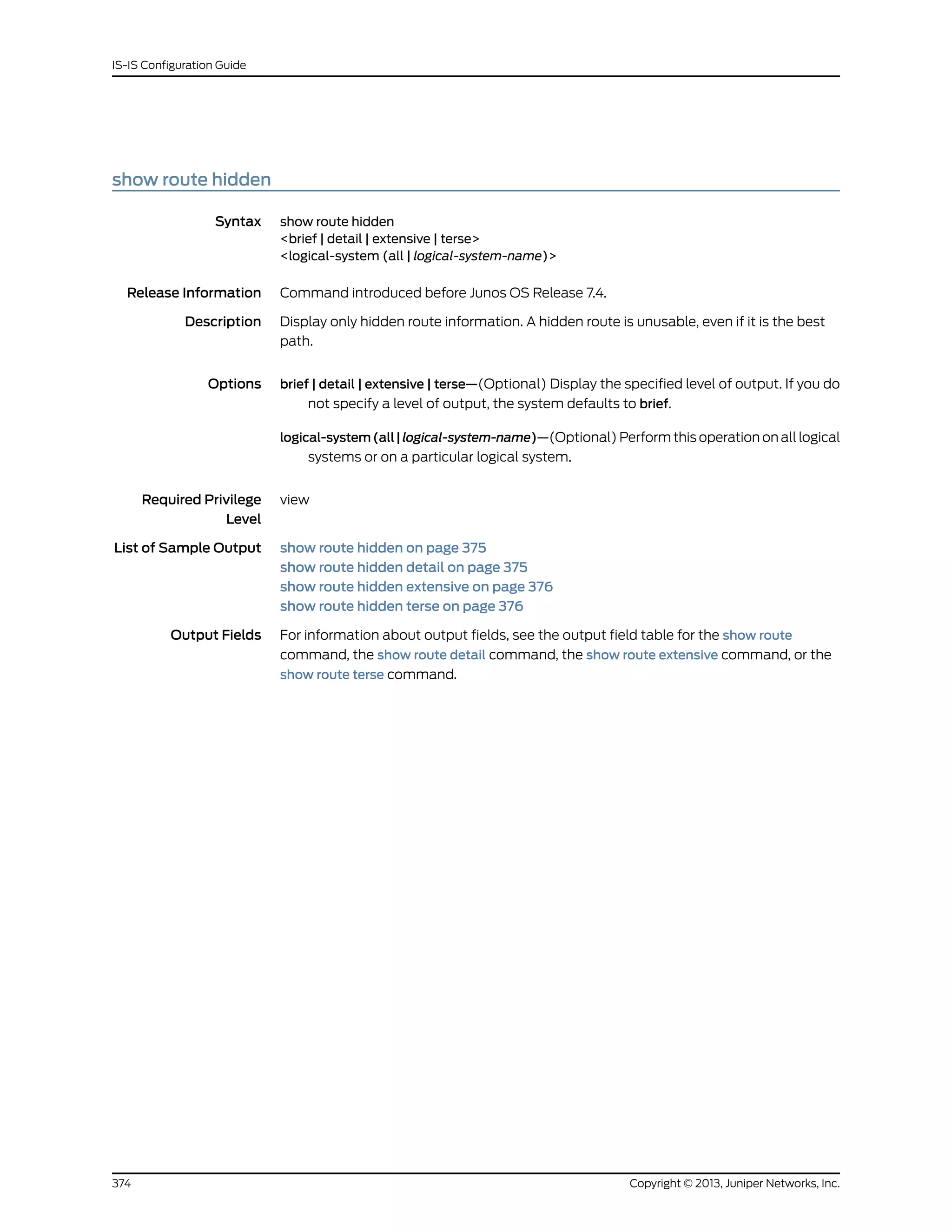
![Sample Output
show route hidden user@host> show route hidden
inet.0: 25 destinations, 26 routes (24 active, 0 holddown, 1 hidden)
Restart Complete
+ = Active Route, - = Last Active, * = Both
127.0.0.1/32 [Direct/0] 04:26:38
> via lo0.0
private1__.inet.0: 2 destinations, 3 routes (2 active, 0 holddown, 0 hidden)
red.inet.0: 6 destinations, 8 routes (4 active, 0 holddown, 3 hidden)
Restart Complete
+ = Active Route, - = Last Active, * = Both
10.5.5.5/32 [BGP/170] 03:44:10, localpref 100, from 10.4.4.4
AS path: 100 I
Unusable
10.12.1.0/24 [BGP/170] 03:44:10, localpref 100, from 10.4.4.4
AS path: 100 I
Unusable
10.12.80.4/30 [BGP/170] 03:44:10, localpref 100, from 10.4.4.4
AS path: I
Unusable
...
show route hidden
detail
user@host> show route hidden detail
inet.0: 25 destinations, 26 routes (24 active, 0 holddown, 1 hidden)
Restart Complete
127.0.0.1/32 (1 entry, 0 announced)
Direct Preference: 0
Next hop type: Interface
Next-hop reference count: 1
Next hop: via lo0.0, selected
State: <Hidden Martian Int>
Local AS: 1
Age: 4:27:37
Task: IF
AS path: I
private1__.inet.0: 2 destinations, 3 routes (2 active, 0 holddown, 0 hidden)
red.inet.0: 6 destinations, 8 routes (4 active, 0 holddown, 3 hidden)
Restart Complete
10.5.5.5/32 (1 entry, 0 announced)
BGP Preference: 170/-101
Route Distinguisher: 10.4.4.4:4
Next hop type: Unusable
Next-hop reference count: 6
State: <Secondary Hidden Int Ext>
Local AS: 1 Peer AS: 1
Age: 3:45:09
Task: BGP_1.10.4.4.4+2493
AS path: 100 I
Communities: target:1:999
VPN Label: 100064
Localpref: 100
Router ID: 10.4.4.4
375Copyright © 2013, Juniper Networks, Inc.
Chapter 6: Operational Commands](https://image.slidesharecdn.com/config-guide-routing-is-is-151104131021-lva1-app6891/75/Juniper-MX-Config-guide-routing-is-is-395-2048.jpg)
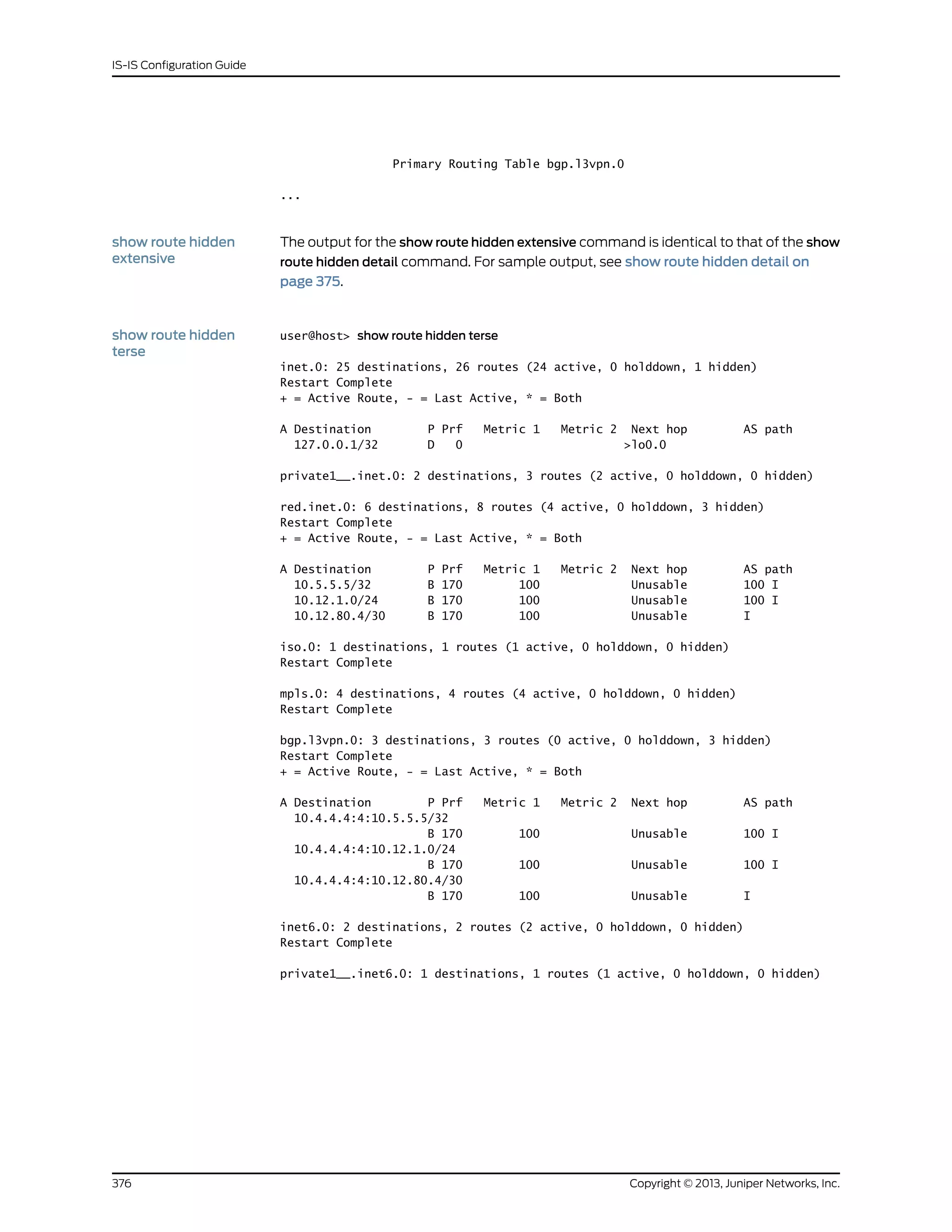
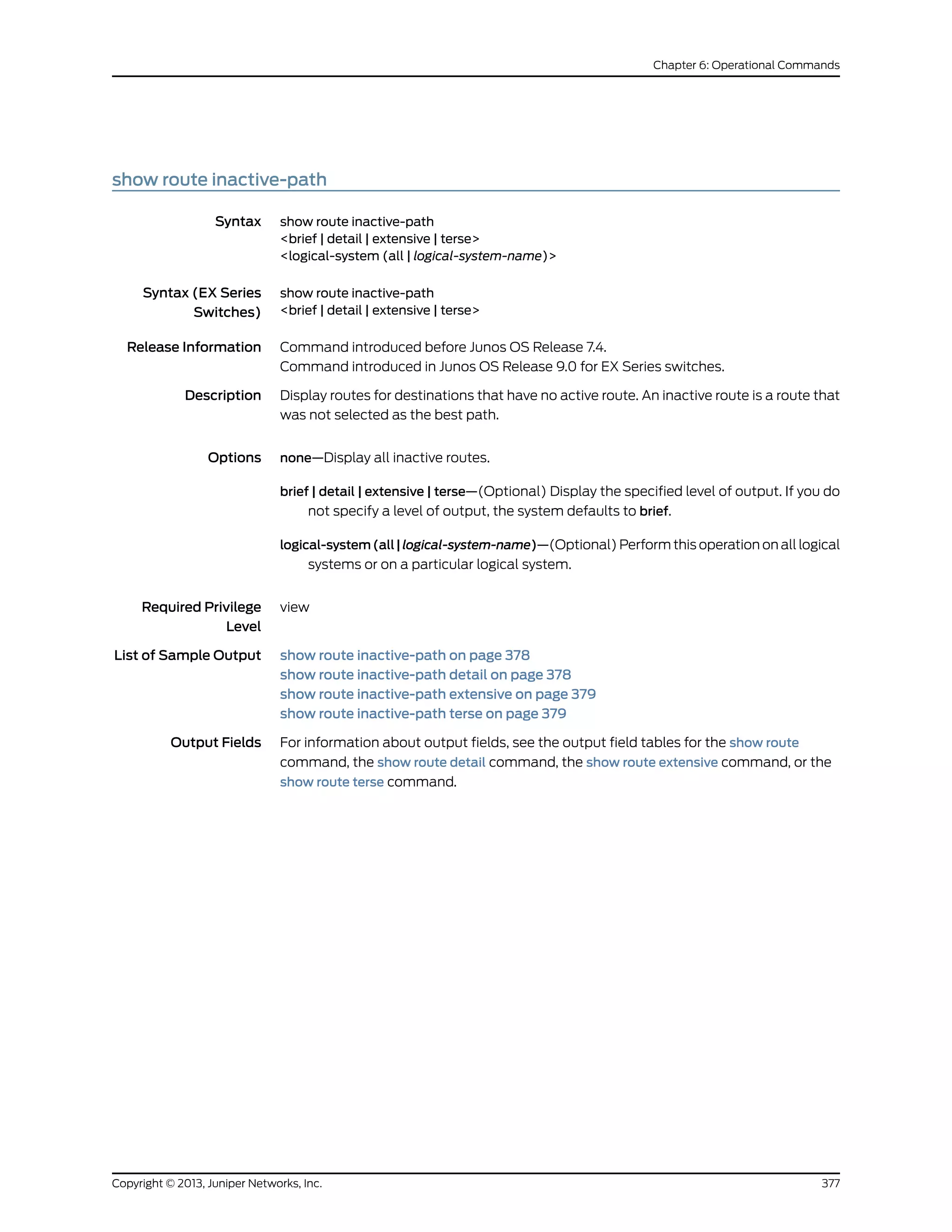
![Sample Output
show route
inactive-path
user@host> show route inactive-path
inet.0: 25 destinations, 26 routes (24 active, 0 holddown, 1 hidden)
Restart Complete
+ = Active Route, - = Last Active, * = Both
10.12.100.12/30 [OSPF/10] 03:57:28, metric 1
> via so-0/3/0.0
private1__.inet.0: 2 destinations, 3 routes (2 active, 0 holddown, 0 hidden)
+ = Active Route, - = Last Active, * = Both
10.0.0.0/8 [Direct/0] 04:39:56
> via fxp1.0
red.inet.0: 6 destinations, 8 routes (4 active, 0 holddown, 3 hidden)
Restart Complete
+ = Active Route, - = Last Active, * = Both
10.12.80.0/30 [BGP/170] 04:38:17, localpref 100
AS path: 100 I
> to 10.12.80.1 via ge-6/3/2.0
iso.0: 1 destinations, 1 routes (1 active, 0 holddown, 0 hidden)
Restart Complete
mpls.0: 4 destinations, 4 routes (4 active, 0 holddown, 0 hidden)
Restart Complete
bgp.l3vpn.0: 3 destinations, 3 routes (0 active, 0 holddown, 3 hidden)
Restart Complete
inet6.0: 2 destinations, 2 routes (2 active, 0 holddown, 0 hidden)
Restart Complete
private1__.inet6.0: 1 destinations, 1 routes (1 active, 0 holddown, 0 hidden)
show route
inactive-path detail
user@host> show route inactive-path detail
inet.0: 25 destinations, 26 routes (24 active, 0 holddown, 1 hidden)
Restart Complete
10.12.100.12/30 (2 entries, 1 announced)
OSPF Preference: 10
Next-hop reference count: 1
Next hop: via so-0/3/0.0, selected
State: <Int>
Inactive reason: Route Preference
Local AS: 1
Age: 3:58:24 Metric: 1
Area: 0.0.0.0
Task: OSPF
AS path: I
private1__.inet.0: 2 destinations, 3 routes (2 active, 0 holddown, 0 hidden)
10.0.0.0/8 (2 entries, 0 announced)
Copyright © 2013, Juniper Networks, Inc.378
IS-IS Configuration Guide](https://image.slidesharecdn.com/config-guide-routing-is-is-151104131021-lva1-app6891/75/Juniper-MX-Config-guide-routing-is-is-398-2048.jpg)
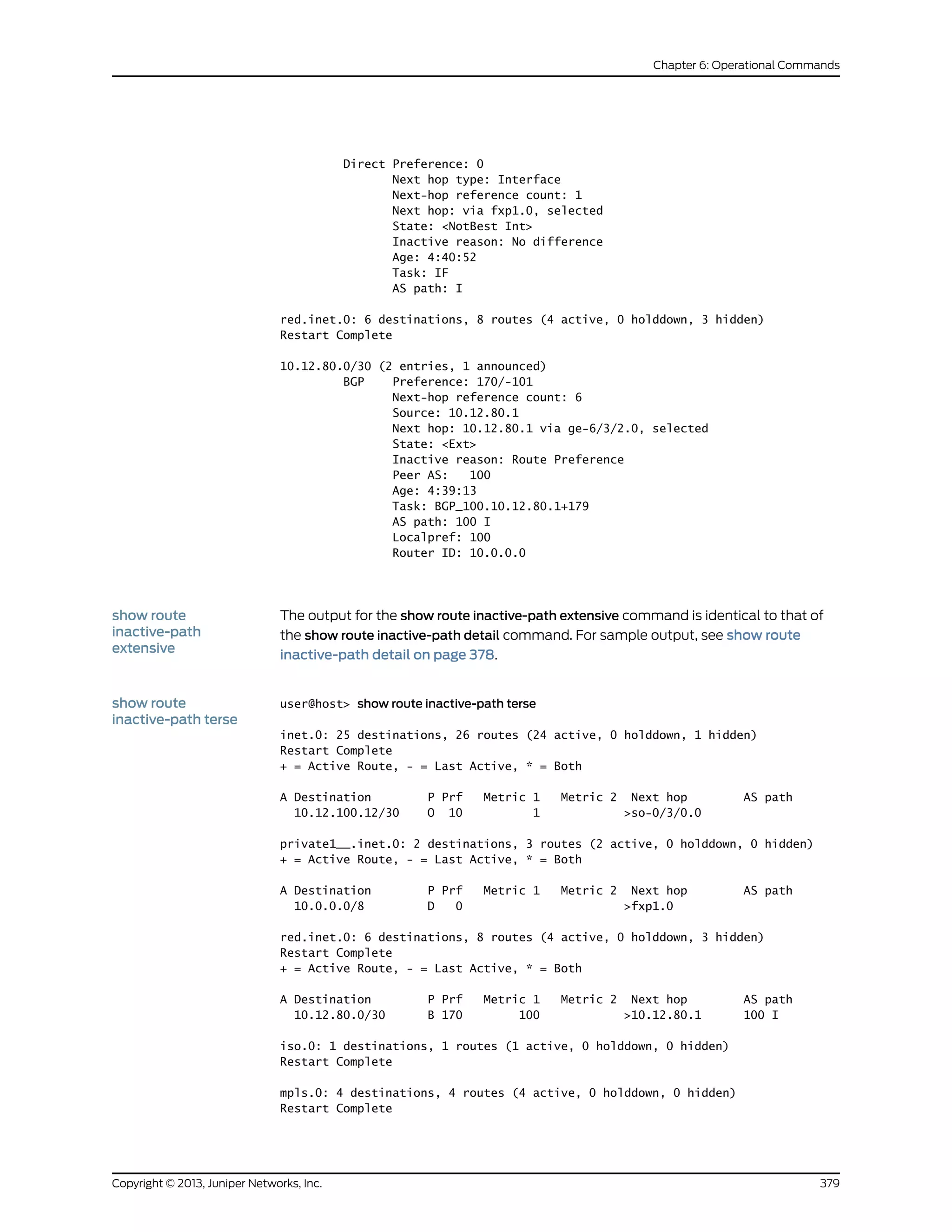

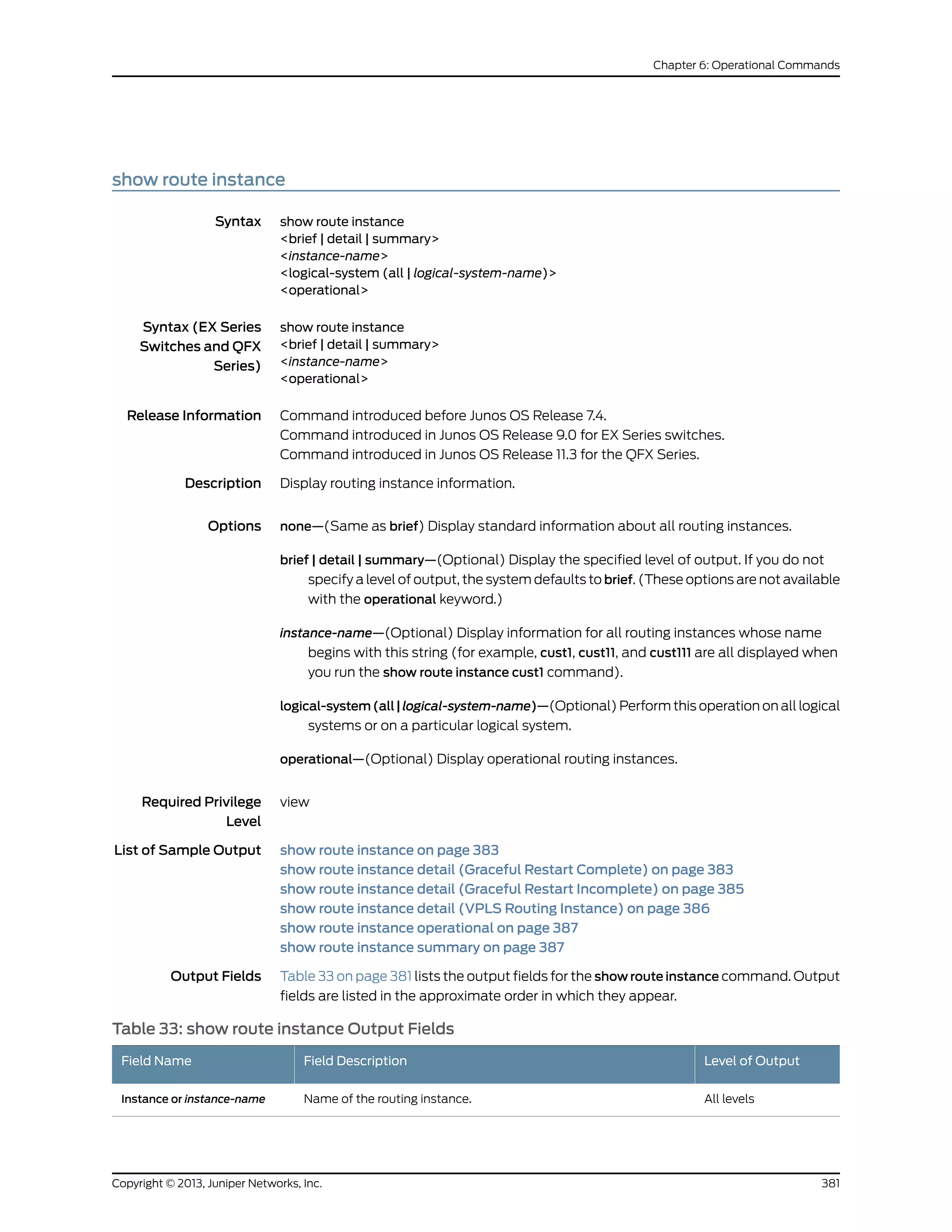
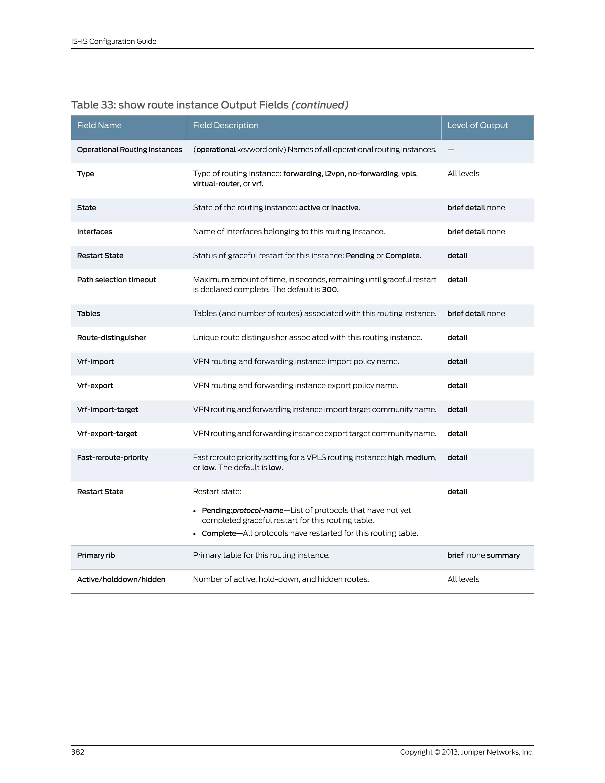
![Sample Output
show route instance user@host> show route instance
Instance Type
Primary RIB Active/holddown/hidden
master forwarding
inet.0 16/0/1
iso.0 1/0/0
mpls.0 0/0/0
inet6.0 2/0/0
l2circuit.0 0/0/0
__juniper_private1__ forwarding
__juniper_private1__.inet.0 12/0/0
__juniper_private1__.inet6.0 1/0/0
show route instance
detail (Graceful
Restart Complete)
user@host> show route instance detail
master:
Router ID: 10.255.14.176
Type: forwarding State: Active
Restart State: Complete Path selection timeout: 300
Tables:
inet.0 : 17 routes (15 active, 0 holddown, 1 hidden)
Restart Complete
inet.3 : 2 routes (2 active, 0 holddown, 0 hidden)
Restart Complete
iso.0 : 1 routes (1 active, 0 holddown, 0 hidden)
Restart Complete
mpls.0 : 19 routes (19 active, 0 holddown, 0 hidden)
Restart Complete
bgp.l3vpn.0 : 10 routes (10 active, 0 holddown, 0 hidden)
Restart Complete
inet6.0 : 2 routes (2 active, 0 holddown, 0 hidden)
Restart Complete
bgp.l2vpn.0 : 1 routes (1 active, 0 holddown, 0 hidden)
Restart Complete
BGP-INET:
Router ID: 10.69.103.1
Type: vrf State: Active
Restart State: Complete Path selection timeout: 300
Interfaces:
t3-0/0/0.103
Route-distinguisher: 10.255.14.176:103
Vrf-import: [ BGP-INET-import ]
Vrf-export: [ BGP-INET-export ]
Tables:
BGP-INET.inet.0 : 4 routes (4 active, 0 holddown, 0 hidden)
Restart Complete
BGP-L:
Router ID: 10.69.104.1
Type: vrf State: Active
Restart State: Complete Path selection timeout: 300
Interfaces:
t3-0/0/0.104
Route-distinguisher: 10.255.14.176:104
Vrf-import: [ BGP-L-import ]
Vrf-export: [ BGP-L-export ]
Tables:
BGP-L.inet.0 : 4 routes (4 active, 0 holddown, 0 hidden)
Restart Complete
383Copyright © 2013, Juniper Networks, Inc.
Chapter 6: Operational Commands](https://image.slidesharecdn.com/config-guide-routing-is-is-151104131021-lva1-app6891/75/Juniper-MX-Config-guide-routing-is-is-403-2048.jpg)
![BGP-L.mpls.0 : 3 routes (3 active, 0 holddown, 0 hidden)
Restart Complete
L2VPN:
Router ID: 0.0.0.0
Type: l2vpn State: Active
Restart State: Complete Path selection timeout: 300
Interfaces:
t3-0/0/0.512
Route-distinguisher: 10.255.14.176:512
Vrf-import: [ L2VPN-import ]
Vrf-export: [ L2VPN-export ]
Tables:
L2VPN.l2vpn.0 : 2 routes (2 active, 0 holddown, 0 hidden)
Restart Complete
LDP:
Router ID: 10.69.105.1
Type: vrf State: Active
Restart State: Complete Path selection timeout: 300
Interfaces:
t3-0/0/0.105
Route-distinguisher: 10.255.14.176:105
Vrf-import: [ LDP-import ]
Vrf-export: [ LDP-export ]
Tables:
LDP.inet.0 : 5 routes (4 active, 0 holddown, 0 hidden)
Restart Complete
OSPF:
Router ID: 10.69.101.1
Type: vrf State: Active
Restart State: Complete Path selection timeout: 300
Interfaces:
t3-0/0/0.101
Route-distinguisher: 10.255.14.176:101
Vrf-import: [ OSPF-import ]
Vrf-export: [ OSPF-export ]
Vrf-import-target: [ target:11111
Tables:
OSPF.inet.0 : 8 routes (7 active, 0 holddown, 0 hidden)
Restart Complete
RIP:
Router ID: 10.69.102.1
Type: vrf State: Active
Restart State: Complete Path selection timeout: 300
Interfaces:
t3-0/0/0.102
Route-distinguisher: 10.255.14.176:102
Vrf-import: [ RIP-import ]
Vrf-export: [ RIP-export ]
Tables:
RIP.inet.0 : 6 routes (6 active, 0 holddown, 0 hidden)
Restart Complete
STATIC:
Router ID: 10.69.100.1
Type: vrf State: Active
Restart State: Complete Path selection timeout: 300
Interfaces:
t3-0/0/0.100
Route-distinguisher: 10.255.14.176:100
Vrf-import: [ STATIC-import ]
Vrf-export: [ STATIC-export ]
Tables:
Copyright © 2013, Juniper Networks, Inc.384
IS-IS Configuration Guide](https://image.slidesharecdn.com/config-guide-routing-is-is-151104131021-lva1-app6891/75/Juniper-MX-Config-guide-routing-is-is-404-2048.jpg)
![STATIC.inet.0 : 4 routes (4 active, 0 holddown, 0 hidden)
Restart Complete
show route instance
detail (Graceful
Restart Incomplete)
user@host> show route instance detail
master:
Router ID: 10.255.14.176
Type: forwarding State: Active
Restart State: Pending Path selection timeout: 300
Tables:
inet.0 : 17 routes (15 active, 1 holddown, 1 hidden)
Restart Pending: OSPF LDP
inet.3 : 2 routes (2 active, 0 holddown, 0 hidden)
Restart Pending: OSPF LDP
iso.0 : 1 routes (1 active, 0 holddown, 0 hidden)
Restart Complete
mpls.0 : 23 routes (23 active, 0 holddown, 0 hidden)
Restart Pending: LDP VPN
bgp.l3vpn.0 : 10 routes (10 active, 0 holddown, 0 hidden)
Restart Pending: BGP VPN
inet6.0 : 2 routes (2 active, 0 holddown, 0 hidden)
Restart Complete
bgp.l2vpn.0 : 1 routes (1 active, 0 holddown, 0 hidden)
Restart Pending: BGP VPN
BGP-INET:
Router ID: 10.69.103.1
Type: vrf State: Active
Restart State: Pending Path selection timeout: 300
Interfaces:
t3-0/0/0.103
Route-distinguisher: 10.255.14.176:103
Vrf-import: [ BGP-INET-import ]
Vrf-export: [ BGP-INET-export ]
Tables:
BGP-INET.inet.0 : 6 routes (5 active, 0 holddown, 0 hidden)
Restart Pending: VPN
BGP-L:
Router ID: 10.69.104.1
Type: vrf State: Active
Restart State: Pending Path selection timeout: 300
Interfaces:
t3-0/0/0.104
Route-distinguisher: 10.255.14.176:104
Vrf-import: [ BGP-L-import ]
Vrf-export: [ BGP-L-export ]
Tables:
BGP-L.inet.0 : 6 routes (5 active, 0 holddown, 0 hidden)
Restart Pending: VPN
BGP-L.mpls.0 : 2 routes (2 active, 0 holddown, 0 hidden)
Restart Pending: VPN
L2VPN:
Router ID: 0.0.0.0
Type: l2vpn State: Active
Restart State: Pending Path selection timeout: 300
Interfaces:
t3-0/0/0.512
Route-distinguisher: 10.255.14.176:512
Vrf-import: [ L2VPN-import ]
Vrf-export: [ L2VPN-export ]
Tables:
L2VPN.l2vpn.0 : 2 routes (2 active, 0 holddown, 0 hidden)
Restart Pending: VPN L2VPN
385Copyright © 2013, Juniper Networks, Inc.
Chapter 6: Operational Commands](https://image.slidesharecdn.com/config-guide-routing-is-is-151104131021-lva1-app6891/75/Juniper-MX-Config-guide-routing-is-is-405-2048.jpg)
![LDP:
Router ID: 10.69.105.1
Type: vrf State: Active
Restart State: Pending Path selection timeout: 300
Interfaces:
t3-0/0/0.105
Route-distinguisher: 10.255.14.176:105
Vrf-import: [ LDP-import ]
Vrf-export: [ LDP-export ]
Tables:
LDP.inet.0 : 5 routes (4 active, 1 holddown, 0 hidden)
Restart Pending: OSPF LDP VPN
OSPF:
Router ID: 10.69.101.1
Type: vrf State: Active
Restart State: Pending Path selection timeout: 300
Interfaces:
t3-0/0/0.101
Route-distinguisher: 10.255.14.176:101
Vrf-import: [ OSPF-import ]
Vrf-export: [ OSPF-export ]
Tables:
OSPF.inet.0 : 8 routes (7 active, 1 holddown, 0 hidden)
Restart Pending: OSPF VPN
RIP:
Router ID: 10.69.102.1
Type: vrf State: Active
Restart State: Pending Path selection timeout: 300
Interfaces:
t3-0/0/0.102
Route-distinguisher: 10.255.14.176:102
Vrf-import: [ RIP-import ]
Vrf-export: [ RIP-export ]
Tables:
RIP.inet.0 : 8 routes (6 active, 2 holddown, 0 hidden)
Restart Pending: RIP VPN
STATIC:
Router ID: 10.69.100.1
Type: vrf State: Active
Restart State: Pending Path selection timeout: 300
Interfaces:
t3-0/0/0.100
Route-distinguisher: 10.255.14.176:100
Vrf-import: [ STATIC-import ]
Vrf-export: [ STATIC-export ]
Tables:
STATIC.inet.0 : 4 routes (4 active, 0 holddown, 0 hidden)
Restart Pending: VPN
show route instance
detail (VPLS Routing
Instance)
user@host> show route instance detail test-vpls
test-vpls:
Router ID: 0.0.0.0
Type: vpls State: Active
Interfaces:
lsi.1048833
lsi.1048832
fe-0/1/0.513
Route-distinguisher: 10.255.37.65:1
Vrf-import: [ __vrf-import-test-vpls-internal__ ]
Vrf-export: [ __vrf-export-test-vpls-internal__ ]
Vrf-import-target: [ target:300:1 ]
Copyright © 2013, Juniper Networks, Inc.386
IS-IS Configuration Guide](https://image.slidesharecdn.com/config-guide-routing-is-is-151104131021-lva1-app6891/75/Juniper-MX-Config-guide-routing-is-is-406-2048.jpg)
![Vrf-export-target: [ target:300:1 ]
Fast-reroute-priority: high
Tables:
test-vpls.l2vpn.0 : 3 routes (3 active, 0 holddown, 0 hidden)
show route instance
operational
user@host> show route instance operational
Operational Routing Instances:
master
default
show route instance
summary
user@host> show route instance summary
Instance Type Primary rib Active/holddown/hidden
master forwarding
inet.0 15/0/1
iso.0 1/0/0
mpls.0 35/0/0
l3vpn.0 0/0/0
inet6.0 2/0/0
l2vpn.0 0/0/0
l2circuit.0 0/0/0
BGP-INET vrf
BGP-INET.inet.0 5/0/0
BGP-INET.iso.0 0/0/0
BGP-INET.inet6.0 0/0/0
BGP-L vrf
BGP-L.inet.0 5/0/0
BGP-L.iso.0 0/0/0
BGP-L.mpls.0 4/0/0
BGP-L.inet6.0 0/0/0
L2VPN l2vpn
L2VPN.inet.0 0/0/0
L2VPN.iso.0 0/0/0
L2VPN.inet6.0 0/0/0
L2VPN.l2vpn.0 2/0/0
LDP vrf
LDP.inet.0 4/0/0
LDP.iso.0 0/0/0
LDP.mpls.0 0/0/0
LDP.inet6.0 0/0/0
LDP.l2circuit.0 0/0/0
OSPF vrf
OSPF.inet.0 7/0/0
OSPF.iso.0 0/0/0
OSPF.inet6.0 0/0/0
RIP vrf
RIP.inet.0 6/0/0
RIP.iso.0 0/0/0
RIP.inet6.0 0/0/0
STATIC vrf
STATIC.inet.0 4/0/0
STATIC.iso.0 0/0/0
STATIC.inet6.0 0/0/0
387Copyright © 2013, Juniper Networks, Inc.
Chapter 6: Operational Commands](https://image.slidesharecdn.com/config-guide-routing-is-is-151104131021-lva1-app6891/75/Juniper-MX-Config-guide-routing-is-is-407-2048.jpg)
![Sample Output
show route next-hop user@host> show route next-hop 192.168.71.254
inet.0: 18 destinations, 18 routes (17 active, 0 holddown, 1 hidden)
Restart Complete
+ = Active Route, - = Last Active, * = Both
10.10.0.0/16 *[Static/5] 06:26:25
> to 192.168.71.254 via fxp0.0
10.209.0.0/16 *[Static/5] 06:26:25
> to 192.168.71.254 via fxp0.0
172.16.0.0/12 *[Static/5] 06:26:25
> to 192.168.71.254 via fxp0.0
192.168.0.0/16 *[Static/5] 06:26:25
> to 192.168.71.254 via fxp0.0
192.168.102.0/23 *[Static/5] 06:26:25
> to 192.168.71.254 via fxp0.0
207.17.136.0/24 *[Static/5] 06:26:25
> to 192.168.71.254 via fxp0.0
207.17.136.192/32 *[Static/5] 06:26:25
> to 192.168.71.254 via fxp0.0
private1__.inet.0: 2 destinations, 3 routes (2 active, 0 holddown, 0 hidden)
red.inet.0: 4 destinations, 5 routes (4 active, 0 holddown, 0 hidden)
Restart Complete
iso.0: 1 destinations, 1 routes (1 active, 0 holddown, 0 hidden)
Restart Complete
mpls.0: 4 destinations, 4 routes (4 active, 0 holddown, 0 hidden)
Restart Complete
inet6.0: 2 destinations, 2 routes (2 active, 0 holddown, 0 hidden)
Restart Complete
private1__.inet6.0: 1 destinations, 1 routes (1 active, 0 holddown, 0 hidden)
show route next-hop
detail
user@host> show route next-hop 192.168.71.254 detail
inet.0: 18 destinations, 18 routes (17 active, 0 holddown, 1 hidden)
Restart Complete
10.10.0.0/16 (1 entry, 1 announced)
*Static Preference: 5
Next-hop reference count: 36
Next hop: 192.168.71.254 via fxp0.0, selected
State: <Active NoReadvrt Int Ext>
Local AS: 1
Age: 6:27:41
Task: RT
Announcement bits (3): 0-KRT 3-Resolve tree 1 5-Resolve tree 2
AS path: I
10.209.0.0/16 (1 entry, 1 announced)
*Static Preference: 5
Next-hop reference count: 36
Next hop: 192.168.71.254 via fxp0.0, selected
State: <Active NoReadvrt Int Ext>
389Copyright © 2013, Juniper Networks, Inc.
Chapter 6: Operational Commands](https://image.slidesharecdn.com/config-guide-routing-is-is-151104131021-lva1-app6891/75/Juniper-MX-Config-guide-routing-is-is-409-2048.jpg)
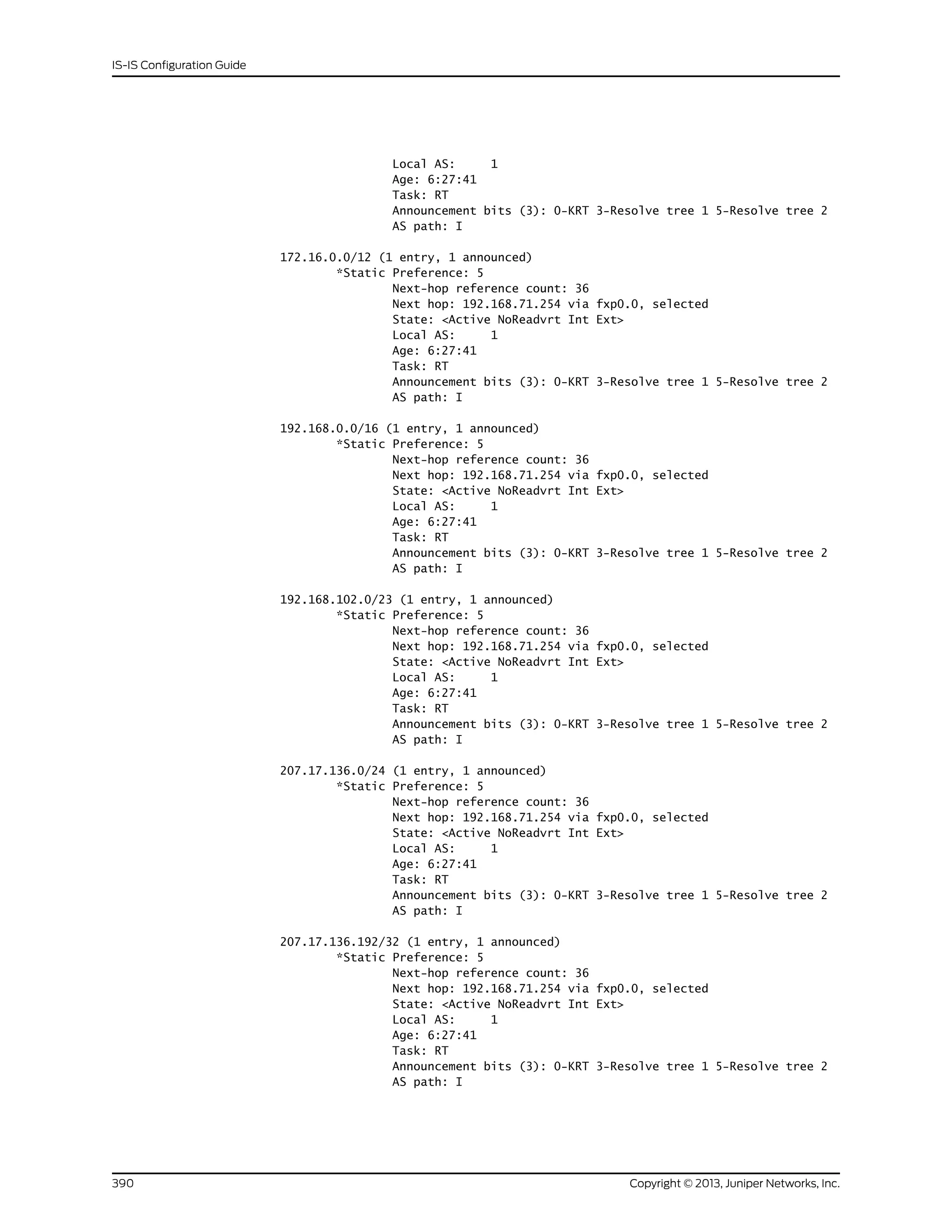
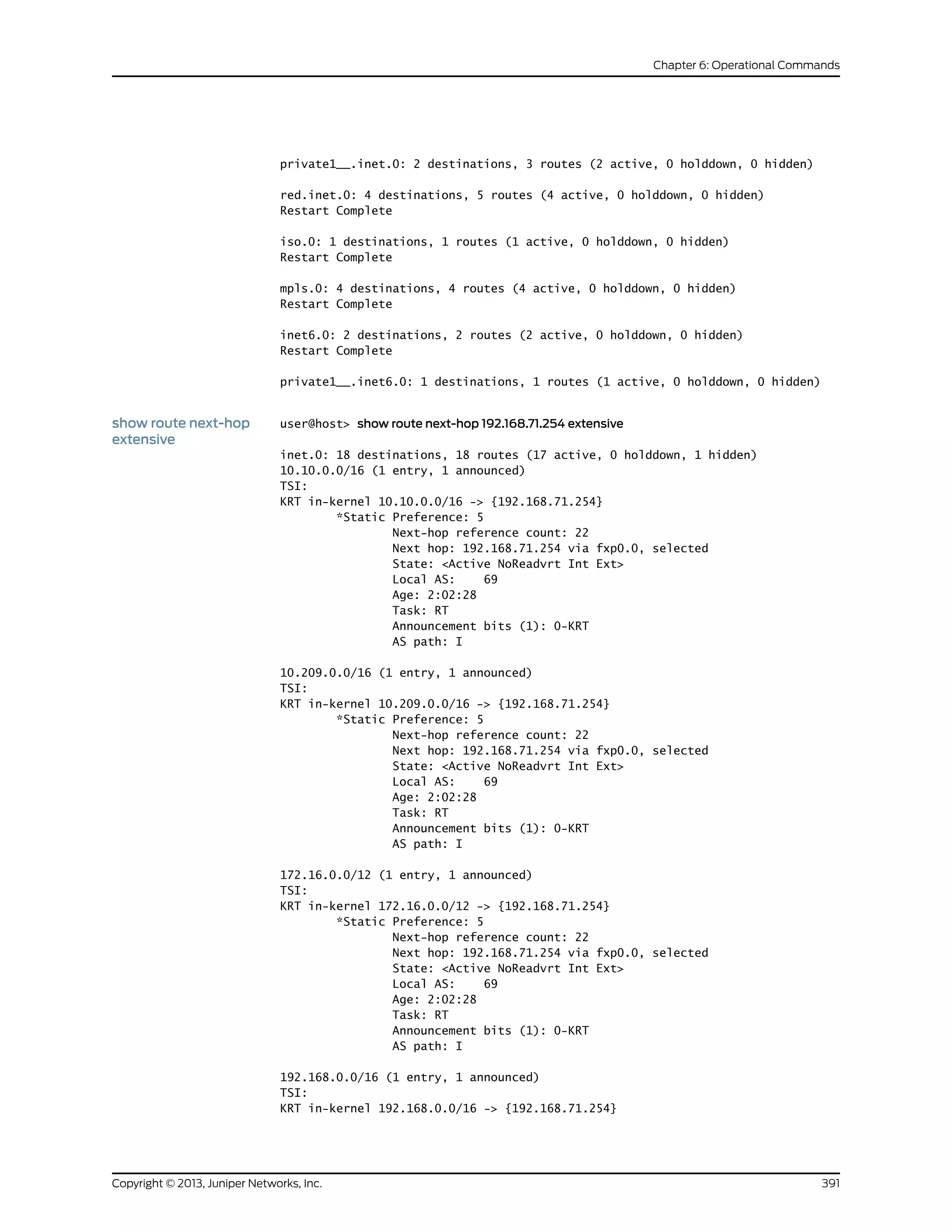
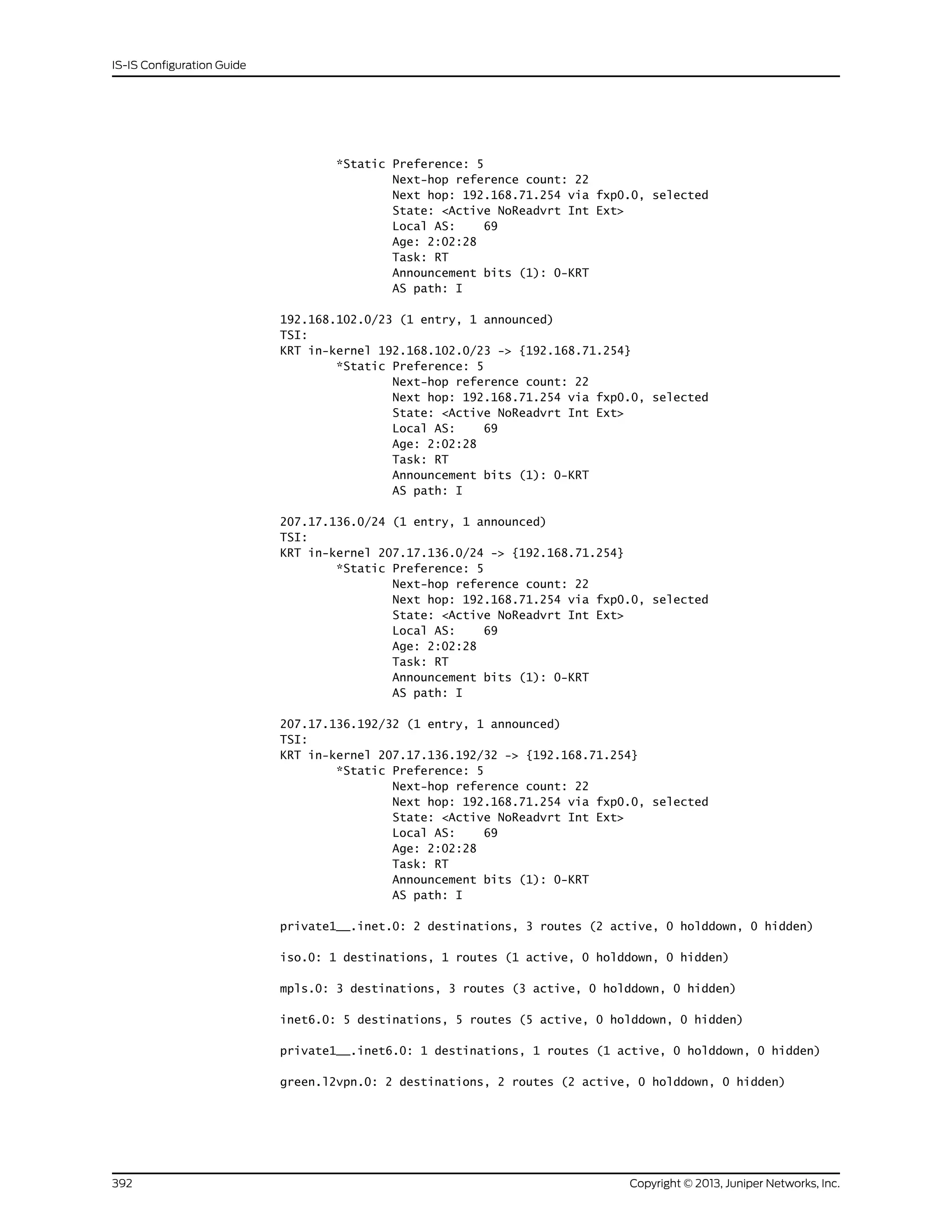
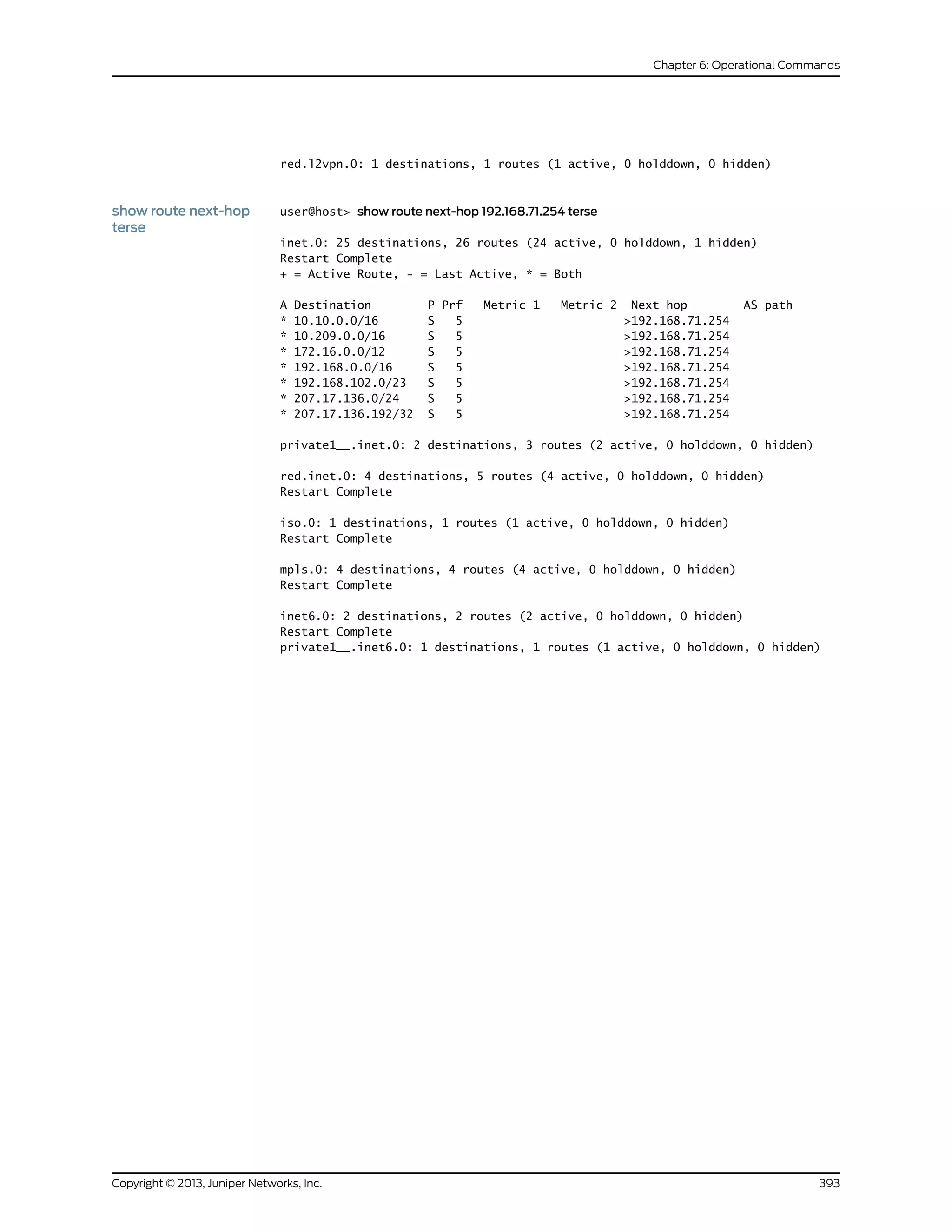
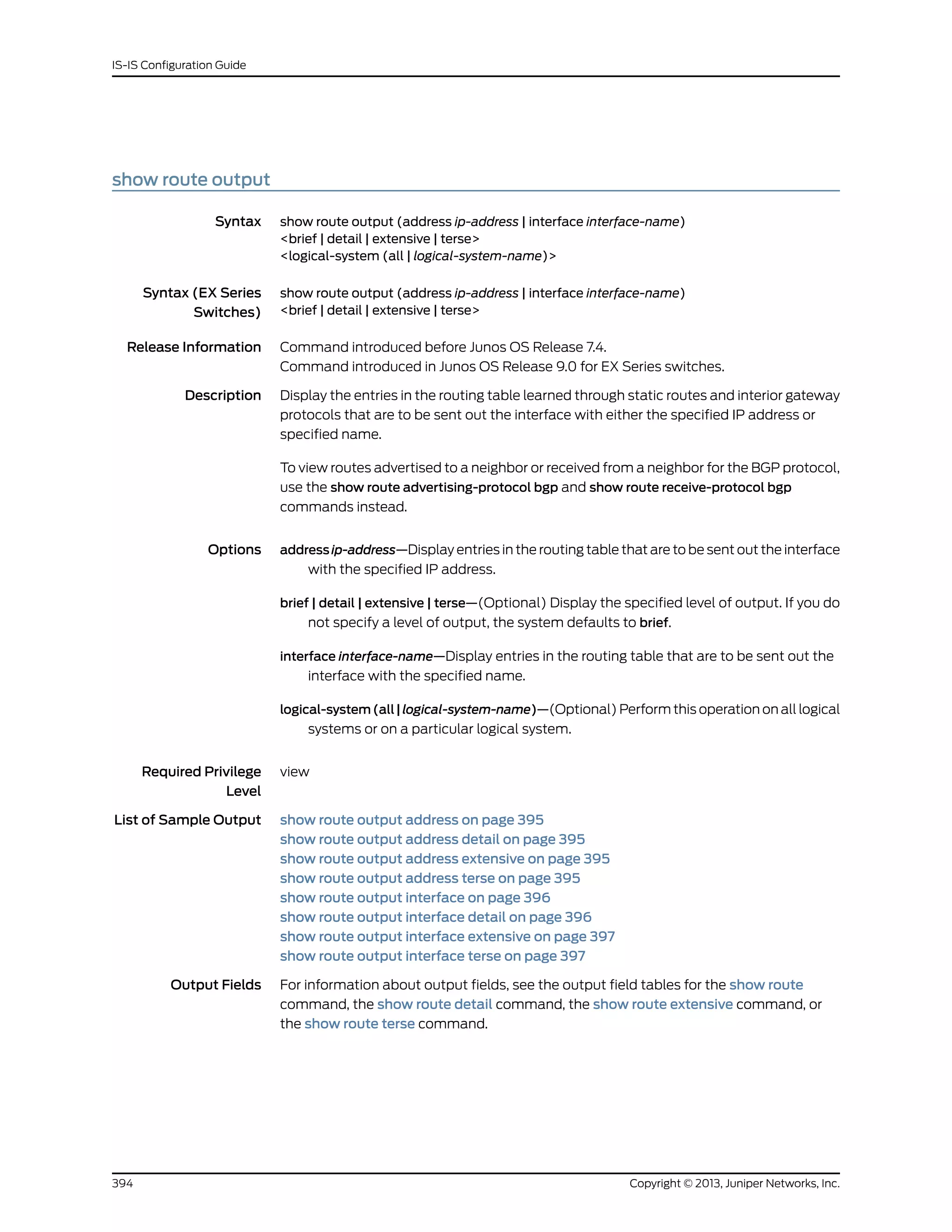
![Sample Output
show route output
address
user@host> show route output address 36.1.1.1/24
inet.0: 28 destinations, 30 routes (27 active, 0 holddown, 1 hidden)
+ = Active Route, - = Last Active, * = Both
36.1.1.0/24 *[Direct/0] 00:19:56
> via so-0/1/2.0
[OSPF/10] 00:19:55, metric 1
> via so-0/1/2.0
private1__.inet.0: 2 destinations, 3 routes (2 active, 0 holddown, 0 hidden)
iso.0: 1 destinations, 1 routes (1 active, 0 holddown, 0 hidden)
mpls.0: 3 destinations, 3 routes (3 active, 0 holddown, 0 hidden)
inet6.0: 2 destinations, 2 routes (2 active, 0 holddown, 0 hidden)
private1__.inet6.0: 1 destinations, 1 routes (1 active, 0 holddown, 0 hidden)
show route output
address detail
user@host> show route output address 36.1.1.1 detail
inet.0: 28 destinations, 30 routes (27 active, 0 holddown, 1 hidden)
36.1.1.0/24 (2 entries, 0 announced)
*Direct Preference: 0
Next hop type: Interface
Next-hop reference count: 1
Next hop: via so-0/1/2.0, selected
State: <Active Int>
Age: 23:00
Task: IF
AS path: I
OSPF Preference: 10
Next-hop reference count: 1
Next hop: via so-0/1/2.0, selected
State: <Int>
Inactive reason: Route Preference
Age: 22:59 Metric: 1
Area: 0.0.0.0
Task: OSPF
AS path: I
private1__.inet.0: 2 destinations, 3 routes (2 active, 0 holddown, 0 hidden)
iso.0: 1 destinations, 1 routes (1 active, 0 holddown, 0 hidden)
mpls.0: 3 destinations, 3 routes (3 active, 0 holddown, 0 hidden)
inet6.0: 2 destinations, 2 routes (2 active, 0 holddown, 0 hidden)
private1__.inet6.0: 1 destinations, 1 routes (1 active, 0 holddown, 0 hidden)
show route output
address extensive
The output for the show route output address extensive command is identical to that of
the show route output address detail command. For sample output, see show route
output address detail on page 395.
395Copyright © 2013, Juniper Networks, Inc.
Chapter 6: Operational Commands](https://image.slidesharecdn.com/config-guide-routing-is-is-151104131021-lva1-app6891/75/Juniper-MX-Config-guide-routing-is-is-415-2048.jpg)
![show route output
address terse
user@host> show route output address 36.1.1.1 terse
inet.0: 28 destinations, 30 routes (27 active, 0 holddown, 1 hidden)
+ = Active Route, - = Last Active, * = Both
A Destination P Prf Metric 1 Metric 2 Next hop AS path
* 36.1.1.0/24 D 0 >so-0/1/2.0
O 10 1 >so-0/1/2.0
private1__.inet.0: 2 destinations, 3 routes (2 active, 0 holddown, 0 hidden)
iso.0: 1 destinations, 1 routes (1 active, 0 holddown, 0 hidden)
mpls.0: 3 destinations, 3 routes (3 active, 0 holddown, 0 hidden)
inet6.0: 2 destinations, 2 routes (2 active, 0 holddown, 0 hidden)
private1__.inet6.0: 1 destinations, 1 routes (1 active, 0 holddown, 0 hidden)
show route output
interface
user@host> show route output interface so-0/1/2.0
inet.0: 28 destinations, 30 routes (27 active, 0 holddown, 1 hidden)
+ = Active Route, - = Last Active, * = Both
10.255.71.240/32 *[OSPF/10] 00:13:00, metric 2
via so-0/1/2.0
> via so-0/3/2.0
10.255.71.241/32 *[OSPF/10] 00:13:10, metric 1
> via so-0/1/2.0
14.1.1.0/24 *[OSPF/10] 00:05:11, metric 3
to 35.1.1.2 via ge-3/1/0.0
> via so-0/1/2.0
via so-0/3/2.0
16.1.1.0/24 *[OSPF/10] 00:13:10, metric 2
> via so-0/1/2.0
36.1.1.0/24 *[Direct/0] 00:13:21
> via so-0/1/2.0
[OSPF/10] 00:13:20, metric 1
> via so-0/1/2.0
private1__.inet.0: 2 destinations, 3 routes (2 active, 0 holddown, 0 hidden)
iso.0: 1 destinations, 1 routes (1 active, 0 holddown, 0 hidden)
mpls.0: 3 destinations, 3 routes (3 active, 0 holddown, 0 hidden)
inet6.0: 2 destinations, 2 routes (2 active, 0 holddown, 0 hidden)
private1__.inet6.0: 1 destinations, 1 routes (1 active, 0 holddown, 0 hidden)
show route output
interface detail
user@host> show route output interface so-0/1/2.0 detail
inet.0: 28 destinations, 30 routes (27 active, 0 holddown, 1 hidden)
10.255.71.240/32 (1 entry, 1 announced)
*OSPF Preference: 10
Next-hop reference count: 2
Next hop: via so-0/1/2.0
Next hop: via so-0/3/2.0, selected
State: <Active Int>
Age: 14:52 Metric: 2
Copyright © 2013, Juniper Networks, Inc.396
IS-IS Configuration Guide](https://image.slidesharecdn.com/config-guide-routing-is-is-151104131021-lva1-app6891/75/Juniper-MX-Config-guide-routing-is-is-416-2048.jpg)
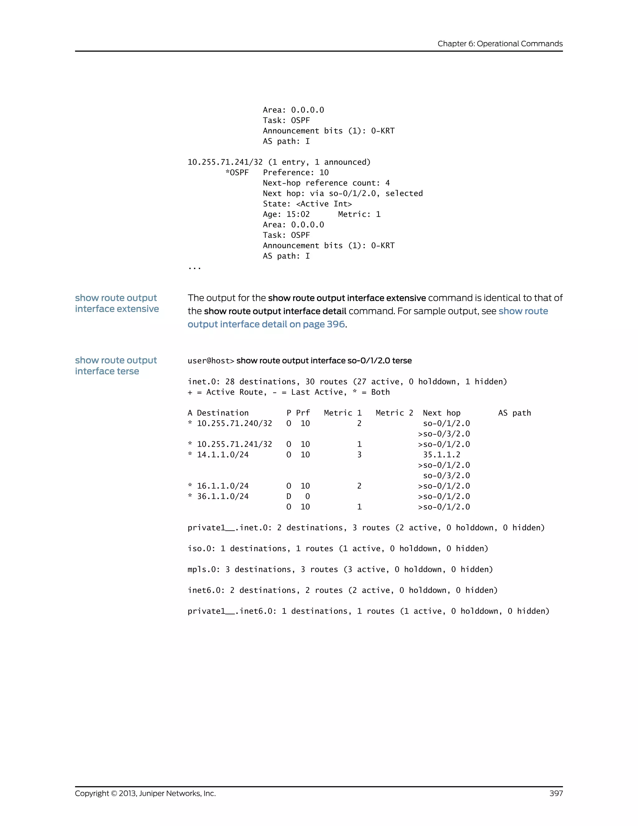
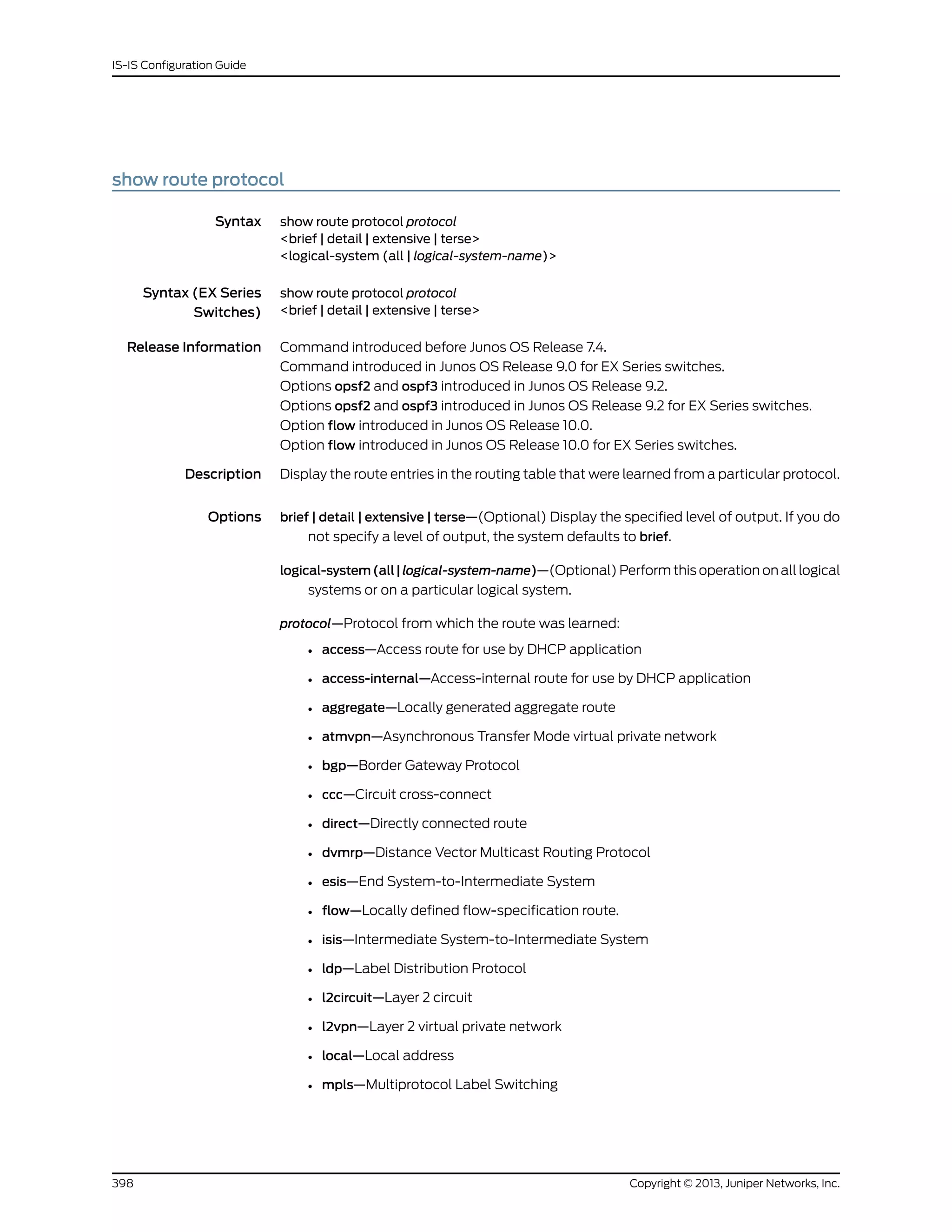
![Sample Output
show route protocol
access
user@host> show route protocol access
inet.0: 30380 destinations, 30382 routes (30379 active, 0 holddown, 1 hidden)
+ = Active Route, - = Last Active, * = Both
13.160.0.3/32 *[Access/13] 00:00:09
> to 13.160.0.2 via fe-0/0/0.0
13.160.0.4/32 *[Access/13] 00:00:09
> to 13.160.0.2 via fe-0/0/0.0
13.160.0.5/32 *[Access/13] 00:00:09
> to 13.160.0.2 via fe-0/0/0.0
show route protocol
access-internal
extensive
user@host> show route protocol access-internal 13.160.0.19 extensive
inet.0: 100020 destinations, 100022 routes (100019 active, 0 holddown, 1 hidden)
13.160.0.19/32 (1 entry, 1 announced)
TSI:
KRT in-kernel 13.160.0.19/32 -> {13.160.0.2}
*Access-internal Preference: 12
Next-hop reference count: 200000
Next hop: 13.160.0.2 via fe-0/0/0.0, selected
State: <Active Int>
Age: 36
Task: RPD Unix Domain Server./var/run/rpd_serv.local
Announcement bits (1): 0-KRT
AS path: I
show route protocol
bgp
user@host> show route protocol bgp 192.168.64.0/21
inet.0: 335832 destinations, 335833 routes (335383 active, 0 holddown, 450 hidden)
+ = Active Route, - = Last Active, * = Both
192.168.64.0/21 *[BGP/170] 6d 10:41:16, localpref 100, from 192.168.69.71
AS path: 10458 14203 2914 4788 4788 I
> to 192.168.167.254 via fxp0.0
show route protocol
bgp detail
user@host> show route protocol bgp 66.117.63.0/24 detail
inet.0: 335805 destinations, 335806 routes (335356 active, 0 holddown, 450 hidden)
66.117.63.0/24 (1 entry, 1 announced)
*BGP Preference: 170/-101
Next hop type: Indirect
Next-hop reference count: 1006436
Source: 192.168.69.71
Next hop type: Router, Next hop index: 324
Next hop: 192.168.167.254 via fxp0.0, selected
Protocol next hop: 192.168.69.71
Indirect next hop: 8e166c0 342
State: <Active Ext>
Local AS: 69 Peer AS: 10458
Age: 6d 10:42:42 Metric2: 0
Task: BGP_10458.192.168.69.71+179
Announcement bits (3): 0-KRT 2-BGP RT Background 3-Resolve tree
1
AS path: 10458 14203 2914 4788 4788 I
Communities: 2914:410 2914:2403 2914:3400
Accepted
Localpref: 100
Router ID: 207.17.136.192
Copyright © 2013, Juniper Networks, Inc.400
IS-IS Configuration Guide](https://image.slidesharecdn.com/config-guide-routing-is-is-151104131021-lva1-app6891/75/Juniper-MX-Config-guide-routing-is-is-420-2048.jpg)
![show route protocol
bgp extensive
user@host> show route protocol bgp 192.168.64.0/21 extensive
inet.0: 335827 destinations, 335828 routes (335378 active, 0 holddown, 450 hidden)
192.168.64.0/21 (1 entry, 1 announced)
TSI:
KRT in-kernel 1.9.0.0/16 -> {indirect(342)}
Page 0 idx 1 Type 1 val db31a80
Nexthop: Self
AS path: [69] 10458 14203 2914 4788 4788 I
Communities: 2914:410 2914:2403 2914:3400
Path 1.9.0.0 from 192.168.69.71 Vector len 4. Val: 1
*BGP Preference: 170/-101
Next hop type: Indirect
Next-hop reference count: 1006502
Source: 192.168.69.71
Next hop type: Router, Next hop index: 324
Next hop: 192.168.167.254 via fxp0.0, selected
Protocol next hop: 192.168.69.71
Indirect next hop: 8e166c0 342
State: <Active Ext>
Local AS: 69 Peer AS: 10458
Age: 6d 10:44:45 Metric2: 0
Task: BGP_10458.192.168.69.71+179
Announcement bits (3): 0-KRT 2-BGP RT Background 3-Resolve tree
1
AS path: 10458 14203 2914 4788 4788 I
Communities: 2914:410 2914:2403 2914:3400
Accepted
Localpref: 100
Router ID: 207.17.136.192
Indirect next hops: 1
Protocol next hop: 192.168.69.71
Indirect next hop: 8e166c0 342
Indirect path forwarding next hops: 1
Next hop type: Router
Next hop: 192.168.167.254 via fxp0.0
192.168.0.0/16 Originating RIB: inet.0
Node path count: 1
Forwarding nexthops: 1
Nexthop: 192.168.167.254 via fxp0.0
show route protocol
bgp terse
user@host> show route protocol bgp 192.168.64.0/21 terse
inet.0: 24 destinations, 32 routes (23 active, 0 holddown, 1 hidden)
+ = Active Route, - = Last Active, * = Both
A Destination P Prf Metric 1 Metric 2 Next hop AS path
192.168.64.0/21 B 170 100 >100.1.3.2 10023 21 I
show route protocol
direct
user@host> show route protocol direct
inet.0: 335843 destinations, 335844 routes (335394 active, 0 holddown, 450 hidden)
+ = Active Route, - = Last Active, * = Both
8.8.8.0/24 *[Direct/0] 17w0d 10:31:49
> via fe-1/3/1.0
10.255.165.1/32 *[Direct/0] 25w4d 04:13:18
> via lo0.0
401Copyright © 2013, Juniper Networks, Inc.
Chapter 6: Operational Commands](https://image.slidesharecdn.com/config-guide-routing-is-is-151104131021-lva1-app6891/75/Juniper-MX-Config-guide-routing-is-is-421-2048.jpg)
![30.30.30.0/24 *[Direct/0] 17w0d 23:06:26
> via fe-1/3/2.0
192.168.164.0/22 *[Direct/0] 25w4d 04:13:20
> via fxp0.0
iso.0: 1 destinations, 1 routes (1 active, 0 holddown, 0 hidden)
+ = Active Route, - = Last Active, * = Both
47.0005.80ff.f800.0000.0108.0001.0102.5516.5001/152
*[Direct/0] 25w4d 04:13:21
> via lo0.0
inet6.0: 2 destinations, 2 routes (2 active, 0 holddown, 0 hidden)
+ = Active Route, - = Last Active, * = Both
abcd::10:255:165:1/128
*[Direct/0] 25w4d 04:13:21
> via lo0.0
fe80::2a0:a5ff:fe12:ad7/128
*[Direct/0] 25w4d 04:13:21
> via lo0.0
show route protocol
l2circuit detail
user@host> show route protocol l2circuit detail
mpls.0: 5 destinations, 5 routes (5 active, 0 holddown, 0 hidden)
100000 (1 entry, 1 announced)
*L2CKT Preference: 7
Next hop: via ge-2/0/0.0, selected
Label operation: Pop Offset: 4
State: <Active Int>
Local AS: 99
Age: 9:52
Task: Common L2 VC
Announcement bits (1): 0-KRT
AS path: I
ge-2/0/0.0 (1 entry, 1 announced)
*L2CKT Preference: 7
Next hop: via so-1/1/2.0 weight 1, selected
Label-switched-path my-lsp
Label operation: Push 100000, Push 100000(top)[0] Offset: -4
Protocol next hop: 10.245.255.63
Push 100000 Offset: -4
Indirect next hop: 86af0c0 298
State: <Active Int>
Local AS: 99
Age: 9:52
Task: Common L2 VC
Announcement bits (2): 0-KRT 1-Common L2 VC
AS path: I
l2circuit.0: 2 destinations, 2 routes (2 active, 0 holddown, 0 hidden)
10.245.255.63:CtrlWord:4:3:Local/96 (1 entry, 1 announced)
*L2CKT Preference: 7
Next hop: via so-1/1/2.0 weight 1, selected
Label-switched-path my-lsp
Label operation: Push 100000[0]
Protocol next hop: 10.245.255.63 Indirect next hop: 86af000 296
State: <Active Int>
Local AS: 99
Copyright © 2013, Juniper Networks, Inc.402
IS-IS Configuration Guide](https://image.slidesharecdn.com/config-guide-routing-is-is-151104131021-lva1-app6891/75/Juniper-MX-Config-guide-routing-is-is-422-2048.jpg)
![Age: 10:21
Task: l2 circuit
Announcement bits (1): 0-LDP
AS path: I
VC Label 100000, MTU 1500, VLAN ID 512
show route protocol
l2vpn extensive
user@host> show route protocol l2vpn extensive
inet.0: 14 destinations, 15 routes (13 active, 0 holddown, 1 hidden)
inet.3: 1 destinations, 1 routes (1 active, 0 holddown, 0 hidden)
iso.0: 1 destinations, 1 routes (1 active, 0 holddown, 0 hidden)
mpls.0: 7 destinations, 7 routes (7 active, 0 holddown, 0 hidden)
800001 (1 entry, 1 announced)
TSI:
KRT in-kernel 800001 /36 -> {so-0/0/0.0}
*L2VPN Preference: 7
Next hop: via so-0/0/0.0 weight 49087 balance 97%, selected
Label operation: Pop Offset: 4
State: <Active Int>
Local AS: 69
Age: 7:48
Task: Common L2 VC
Announcement bits (1): 0-KRT
AS path: I
so-0/0/0.0 (1 entry, 1 announced)
TSI:
KRT in-kernel so-0/0/0.0.0 /16 -> {indirect(288)}
*L2VPN Preference: 7
Next hop: via so-0/0/1.0, selected
Label operation: Push 800000 Offset: -4
Protocol next hop: 10.255.14.220
Push 800000 Offset: -4
Indirect next hop: 85142a0 288
State: <Active Int>
Local AS: 69
Age: 7:48
Task: Common L2 VC
Announcement bits (2): 0-KRT 1-Common L2 VC
AS path: I
Communities: target:69:1 Layer2-info: encaps:PPP,
control flags:2, mtu: 0
show route protocol
ldp
user@host> show route protocol ldp
inet.0: 12 destinations, 13 routes (12 active, 0 holddown, 0 hidden)
inet.3: 2 destinations, 2 routes (2 active, 0 holddown, 0 hidden)
+ = Active Route, - = Last Active, * = Both
192.168.16.1/32 *[LDP/9] 1d 23:03:35, metric 1
> via t1-4/0/0.0, Push 100000
192.168.17.1/32 *[LDP/9] 1d 23:03:35, metric 1
> via t1-4/0/0.0
private1__.inet.0: 2 destinations, 2 routes (2 active, 0 holddown, 0 hidden)
mpls.0: 6 destinations, 6 routes (6 active, 0 holddown, 0 hidden)
403Copyright © 2013, Juniper Networks, Inc.
Chapter 6: Operational Commands](https://image.slidesharecdn.com/config-guide-routing-is-is-151104131021-lva1-app6891/75/Juniper-MX-Config-guide-routing-is-is-423-2048.jpg)
![+ = Active Route, - = Last Active, * = Both
100064 *[LDP/9] 1d 23:03:35, metric 1
> via t1-4/0/0.0, Pop
100064(S=0) *[LDP/9] 1d 23:03:35, metric 1
> via t1-4/0/0.0, Pop
100080 *[LDP/9] 1d 23:03:35, metric 1
> via t1-4/0/0.0, Swap 100000
show route protocol
ldp extensive
user@host> show route protocol ldp extensive
192.168.16.1/32 (1 entry, 1 announced)
State: <FlashAll>
*LDP Preference: 9
Next-hop reference count: 3
Next hop: via t1-4/0/0.0, selected
Label operation: Push 100000
State: <Active Int>
Local AS: 65500
Age: 1d 23:03:58 Metric: 1
Task: LDP
Announcement bits (2): 0-Resolve tree 1 2-Resolve tree 2
AS path: I
192.168.17.1/32 (1 entry, 1 announced)
State: <FlashAll>
*LDP Preference: 9
Next-hop reference count: 3
Next hop: via t1-4/0/0.0, selected
State: <Active Int>
Local AS: 65500
Age: 1d 23:03:58 Metric: 1
Task: LDP
Announcement bits (2): 0-Resolve tree 1 2-Resolve tree 2
AS path: I
private1__.inet.0: 2 destinations, 2 routes (2 active, 0 holddown, 0 hidden)
mpls.0: 6 destinations, 6 routes (6 active, 0 holddown, 0 hidden)
100064 (1 entry, 1 announced)
TSI:
KRT in-kernel 100064 /36 -> {t1-4/0/0.0}
*LDP Preference: 9
Next-hop reference count: 2
Next hop: via t1-4/0/0.0, selected
State: <Active Int>
Local AS: 65500
Age: 1d 23:03:58 Metric: 1
Task: LDP
Announcement bits (1): 0-KRT
AS path: I
Prefixes bound to route: 192.168.17.1/32
100064(S=0) (1 entry, 1 announced)
TSI:
KRT in-kernel 100064 /40 -> {t1-4/0/0.0}
*LDP Preference: 9
Next-hop reference count: 2
Next hop: via t1-4/0/0.0, selected
Label operation: Pop
State: <Active Int>
Copyright © 2013, Juniper Networks, Inc.404
IS-IS Configuration Guide](https://image.slidesharecdn.com/config-guide-routing-is-is-151104131021-lva1-app6891/75/Juniper-MX-Config-guide-routing-is-is-424-2048.jpg)
![Local AS: 65500
Age: 1d 23:03:58 Metric: 1
Task: LDP
Announcement bits (1): 0-KRT
AS path: I
100080 (1 entry, 1 announced)
TSI:
KRT in-kernel 100080 /36 -> {t1-4/0/0.0}
*LDP Preference: 9
Next-hop reference count: 2
Next hop: via t1-4/0/0.0, selected
Label operation: Swap 100000
State: <Active Int>
Local AS: 65500
Age: 1d 23:03:58 Metric: 1
Task: LDP
Announcement bits (1): 0-KRT
AS path: I
Prefixes bound to route: 192.168.16.1/32
show route protocol
ospf (Layer 3 VPN)
user@host> show route protocol ospf
inet.0: 40 destinations, 40 routes (39 active, 0 holddown, 1 hidden)
+ = Active Route, - = Last Active, * = Both
10.39.1.4/30 *[OSPF/10] 00:05:18, metric 4
> via t3-3/2/0.0
10.39.1.8/30 [OSPF/10] 00:05:18, metric 2
> via t3-3/2/0.0
10.255.14.171/32 *[OSPF/10] 00:05:18, metric 4
> via t3-3/2/0.0
10.255.14.179/32 *[OSPF/10] 00:05:18, metric 2
> via t3-3/2/0.0
224.0.0.5/32 *[OSPF/10] 20:25:55, metric 1
VPN-AB.inet.0: 5 destinations, 5 routes (5 active, 0 holddown, 0 hidden)
+ = Active Route, - = Last Active, * = Both
10.39.1.16/30 [OSPF/10] 00:05:43, metric 1
> via so-0/2/2.0
10.255.14.173/32 *[OSPF/10] 00:05:43, metric 1
> via so-0/2/2.0
224.0.0.5/32 *[OSPF/10] 20:26:20, metric 1
show route protocol
ospf detail
user@host> show route protocol ospf detail
VPN-AB.inet.0: 5 destinations, 5 routes (5 active, 0 holddown, 0 hidden)
+ = Active Route, - = Last Active, * = Both
10.39.1.16/30 (2 entries, 0 announced)
OSPF Preference: 10
Nexthop: via so-0/2/2.0, selected
State: <Int>
Inactive reason: Route Preference
Age: 6:25 Metric: 1
Area: 0.0.0.0
Task: VPN-AB-OSPF
AS path: I
Communities: Route-Type:0.0.0.0:1:0
...
405Copyright © 2013, Juniper Networks, Inc.
Chapter 6: Operational Commands](https://image.slidesharecdn.com/config-guide-routing-is-is-151104131021-lva1-app6891/75/Juniper-MX-Config-guide-routing-is-is-425-2048.jpg)
![showrouteprotocolrip user@host> show route protocol rip
inet.0: 26 destinations, 27 routes (25 active, 0 holddown, 1 hidden)
+ = Active Route, - = Last Active, * = Both
VPN-AB.inet.0: 5 destinations, 5 routes (5 active, 0 holddown, 0 hidden)
+ = Active Route, - = Last Active, * = Both
10.255.14.177/32 *[RIP/100] 20:24:34, metric 2
> to 10.39.1.22 via t3-0/2/2.0
224.0.0.9/32 *[RIP/100] 00:03:59, metric 1
showrouteprotocolrip
detail
user@host> show route protocol rip detail
inet.0: 26 destinations, 27 routes (25 active, 0 holddown, 1 hidden)
+ = Active Route, - = Last Active, * = Both
VPN-AB.inet.0: 5 destinations, 5 routes (5 active, 0 holddown, 0 hidden)
+ = Active Route, - = Last Active, * = Both
10.255.14.177/32 (1 entry, 1 announced)
*RIP Preference: 100
Nexthop: 10.39.1.22 via t3-0/2/2.0, selected
State: <Active Int>
Age: 20:25:02 Metric: 2
Task: VPN-AB-RIPv2
Announcement bits (2): 0-KRT 2-BGP.0.0.0.0+179
AS path: I
Route learned from 10.39.1.22 expires in 96 seconds
show route protocol
ripng table inet6
user@host> show route protocol ripng table inet6
inet6.0: 4215 destinations, 4215 routes (4214 active, 0 holddown, 1 hidden)
+ = Active Route, - = Last Active, * = Both
1111::1/128 *[RIPng/100] 02:13:33, metric 2
> to fe80::2a0:a5ff:fe3d:56 via t3-0/2/0.0
1111::2/128 *[RIPng/100] 02:13:33, metric 2
> to fe80::2a0:a5ff:fe3d:56 via t3-0/2/0.0
1111::3/128 *[RIPng/100] 02:13:33, metric 2
> to fe80::2a0:a5ff:fe3d:56 via t3-0/2/0.0
1111::4/128 *[RIPng/100] 02:13:33, metric 2
> to fe80::2a0:a5ff:fe3d:56 via t3-0/2/0.0
1111::5/128 *[RIPng/100] 02:13:33, metric 2
> to fe80::2a0:a5ff:fe3d:56 via t3-0/2/0.0
1111::6/128 *[RIPng/100] 02:13:33, metric 2
> to fe80::2a0:a5ff:fe3d:56 via t3-0/2/0.0
Copyright © 2013, Juniper Networks, Inc.406
IS-IS Configuration Guide](https://image.slidesharecdn.com/config-guide-routing-is-is-151104131021-lva1-app6891/75/Juniper-MX-Config-guide-routing-is-is-426-2048.jpg)
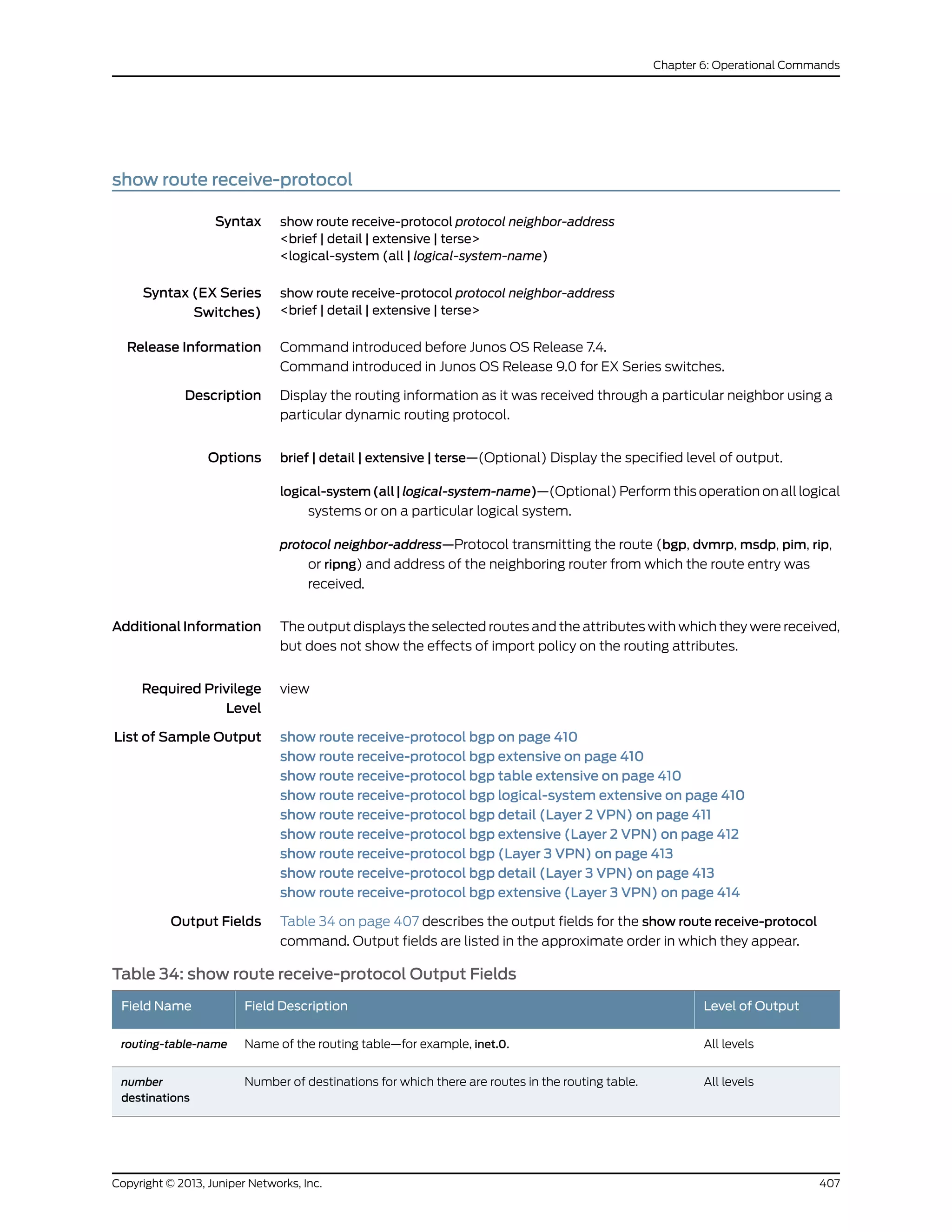
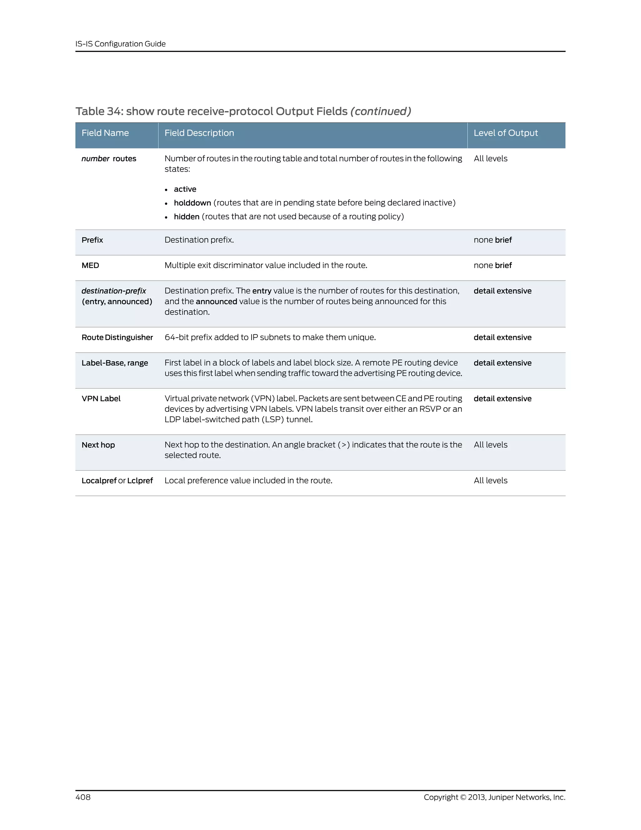
![Table 34: show route receive-protocol Output Fields (continued)
Level of OutputField DescriptionField Name
All levelsAutonomous system (AS) path through which the route was learned. The letters
at the end of the AS path indicate the path origin, providing an indication of the
state of the route at the point at which the AS path originated:
• I—IGP.
• E—EGP.
• ?—Incomplete; typically, the AS path was aggregated.
When AS path numbers are included in the route, the format is as follows:
• [ ]—Brackets enclose the number that precedes the AS path. This number
represents the number of ASs present in the AS path, when calculated as
defined in RFC 4271. This value is used the AS-path merge process, as defined
in RFC 4893.
• [ ]—If more than one AS number is configured on the router, or if AS path
prepending is configured, brackets enclose the local AS number associated
with the AS path.
• { }—Braces enclose AS sets, which are groups of AS numbers in which the
order does not matter. A set commonly results from route aggregation. The
numbers in each AS set are displayed in ascending order.
• ( )—Parentheses enclose a confederation.
• ( [ ] )—Parentheses and brackets enclose a confederation set.
NOTE: In Junos OS Release 10.3 and later, the AS path field displays an
unrecognized attribute and associated hexadecimal value if BGP receives
attribute 128 (attribute set) and you have not configured an independent domain
in any routing instance.
AS path
detail extensive(For route reflected output only) Cluster ID sent by the route reflector.Cluster list
detail extensive(For route reflected output only) Address of routing device that originally sent
the route to the route reflector.
Originator ID
detail extensiveCommunity path attribute for the route. See the Output Field table in the show
route detail command for all possible values for this field.
Communities
detail extensiveAccumulated interior gateway protocol (AIGP) BGP attribute.AIGP
detail extensiveNumber, local preference, and path of the AS that originated the route. These
values are stored in the Attrset attribute at the originating routing device.
Attrset AS
detail extensiveLayer 2 encapsulation (for example, VPLS).Layer2-info: encaps
detail extensiveControl flags: none or Site Down.control flags
detail extensiveMaximum transmission unit (MTU) of the Layer 2 circuit.mtu
409Copyright © 2013, Juniper Networks, Inc.
Chapter 6: Operational Commands](https://image.slidesharecdn.com/config-guide-routing-is-is-151104131021-lva1-app6891/75/Juniper-MX-Config-guide-routing-is-is-429-2048.jpg)
![Sample Output
show route
receive-protocol bgp
user@host> show route receive-protocol bgp 10.255.245.215
inet.0: 28 destinations, 33 routes (27 active, 0 holddown, 1 hidden)
Prefix Next hop MED Lclpref AS path
10.22.1.0/24 10.255.245.215 0 100 I
10.22.2.0/24 10.255.245.215 0 100 I
show route
receive-protocol bgp
extensive
user@host> show route receive-protocol bgp 10.255.245.63 extensive
inet.0: 244 destinations, 244 routes (243 active, 0 holddown, 1 hidden)
Prefix Next hop MED Lclpref AS path
1.1.1.0/24 (1 entry, 1 announced)
Next hop: 10.0.50.3
Localpref: 100
AS path: I <Orginator>
Cluster list: 10.2.3.1
Originator ID: 10.255.245.45
165.3.0.0/16 (1 entry, 1 announced)
Next hop: 111.222.5.254
Localpref: 100
AS path: I <Originator>
Cluster list: 10.2.3.1
Originator ID: 10.255.245.68
165.4.0.0/16 (1 entry, 1 announced)
Next hop: 111.222.5.254
Localpref: 100
AS path: I <Originator>
Cluster list: 10.2.3.1
Originator ID: 10.255.245.45
195.1.2.0/24 (1 entry, 1 announced)
Next hop: 111.222.5.254
Localpref: 100
AS path: I <Originator>
Cluster list: 10.2.3.1
Originator ID: 10.255.245.68
inet.2: 63 destinations, 63 routes (63 active, 0 holddown, 0 hidden)
Prefix Next hop MED Lclpref AS path
inet.3: 10 destinations, 10 routes (10 active, 0 holddown, 0 hidden)
Prefix Next hop MED Lclpref AS path
iso.0: 1 destinations, 1 routes (1 active, 0 holddown, 0 hidden)
Prefix Next hop MED Lclpref AS path
mpls.0: 48 destinations, 48 routes (48 active, 0 holddown, 0 hidden)
show route
receive-protocol bgp
table extensive
user@host> show route receive-protocol bgp 207.17.136.192 table inet.0 66.117.68.0/24 extensive
inet.0: 227315 destinations, 227316 routes (227302 active, 0 holddown, 13 hidden)
* 66.117.63.0/24 (1 entry, 1 announced)
Nexthop: 207.17.136.29
Localpref: 100
AS path: AS2 PA[6]: 14203 2914 3356 29748 33437 AS_TRANS
AS path: AS4 PA[2]: 33437 393219
AS path: Merged[6]: 14203 2914 3356 29748 33437 393219 I
Communities: 2914:420
show route
receive-protocol bgp
user@host> show route receive-protocol bgp 10.0.0.9 logical-system PE4 extensive
inet.0: 12 destinations, 13 routes (12 active, 0 holddown, 0 hidden)
* 10.0.0.0/30 (1 entry, 1 announced)
Copyright © 2013, Juniper Networks, Inc.410
IS-IS Configuration Guide](https://image.slidesharecdn.com/config-guide-routing-is-is-151104131021-lva1-app6891/75/Juniper-MX-Config-guide-routing-is-is-430-2048.jpg)
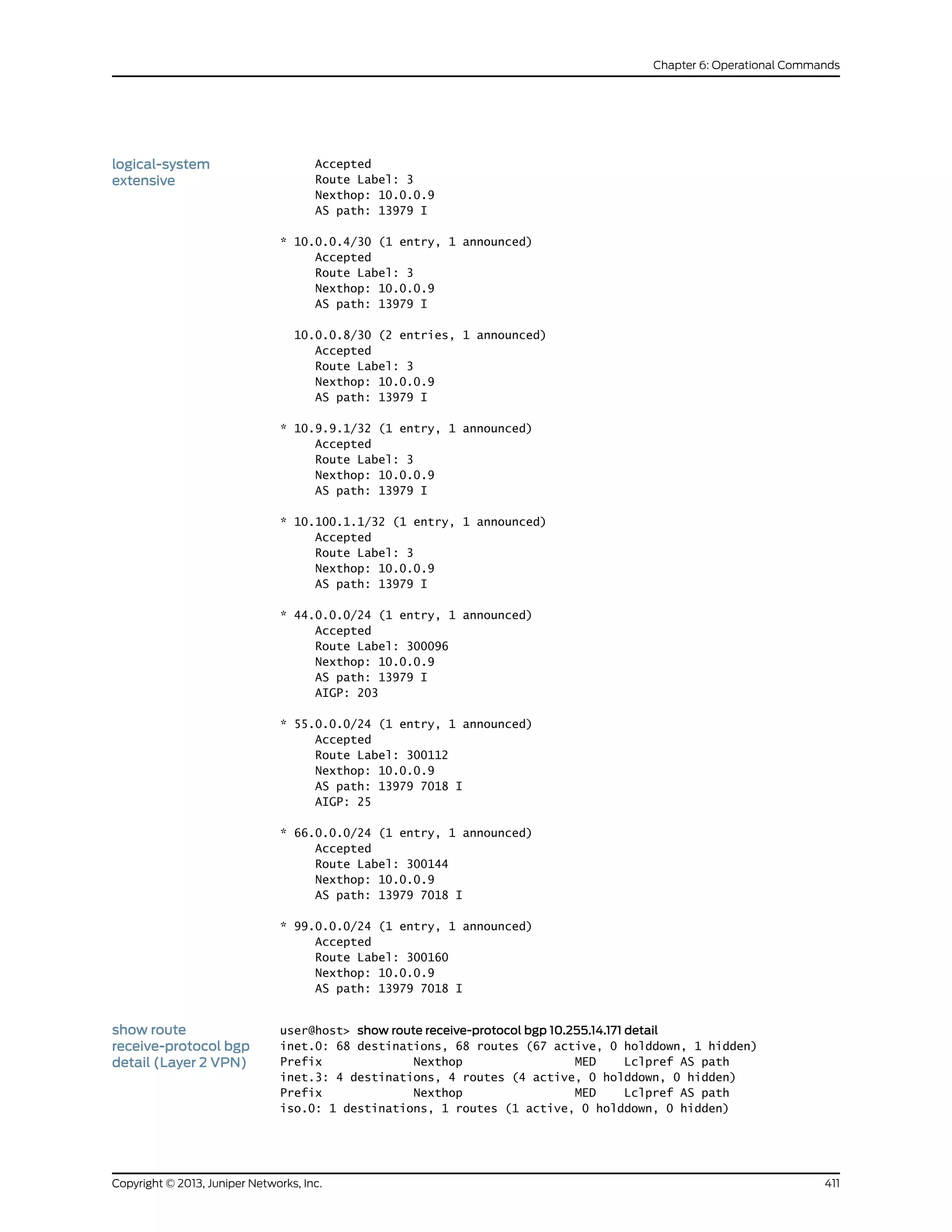
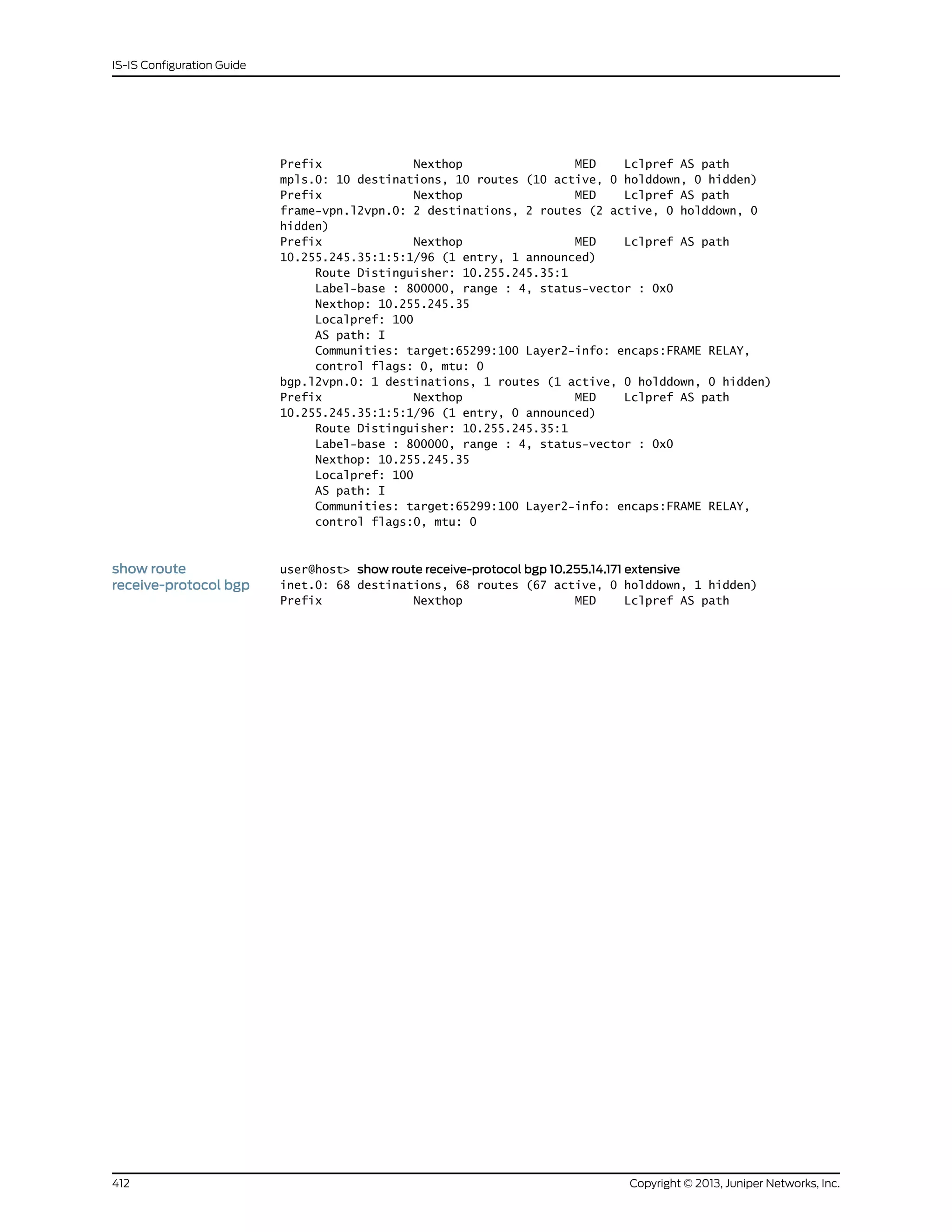
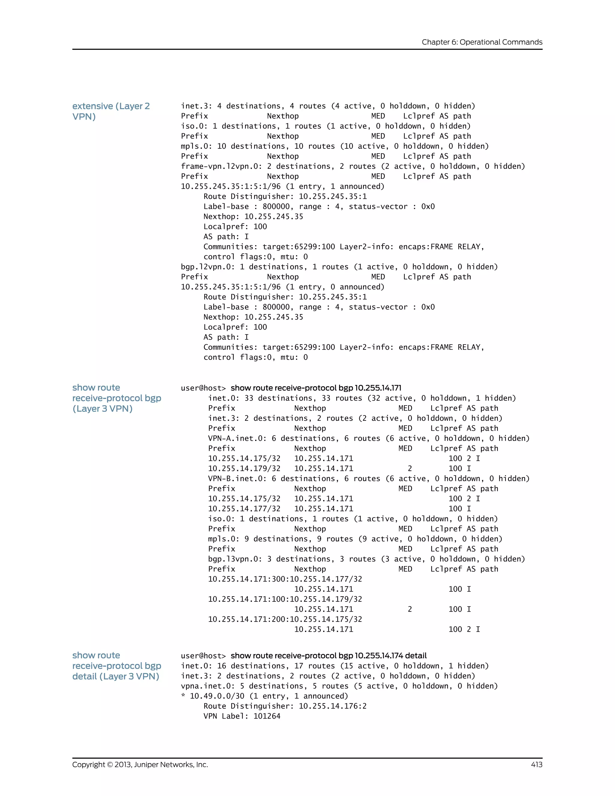
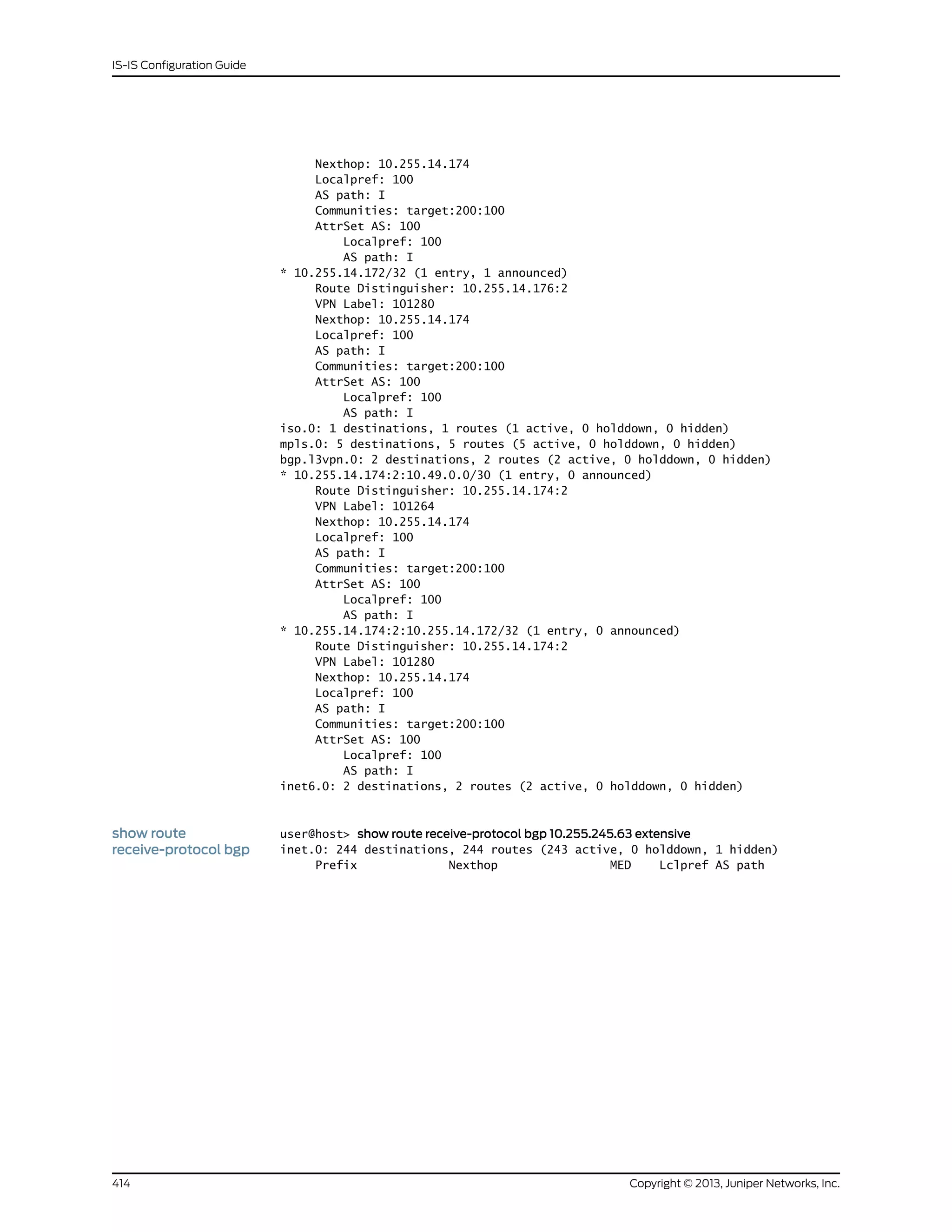
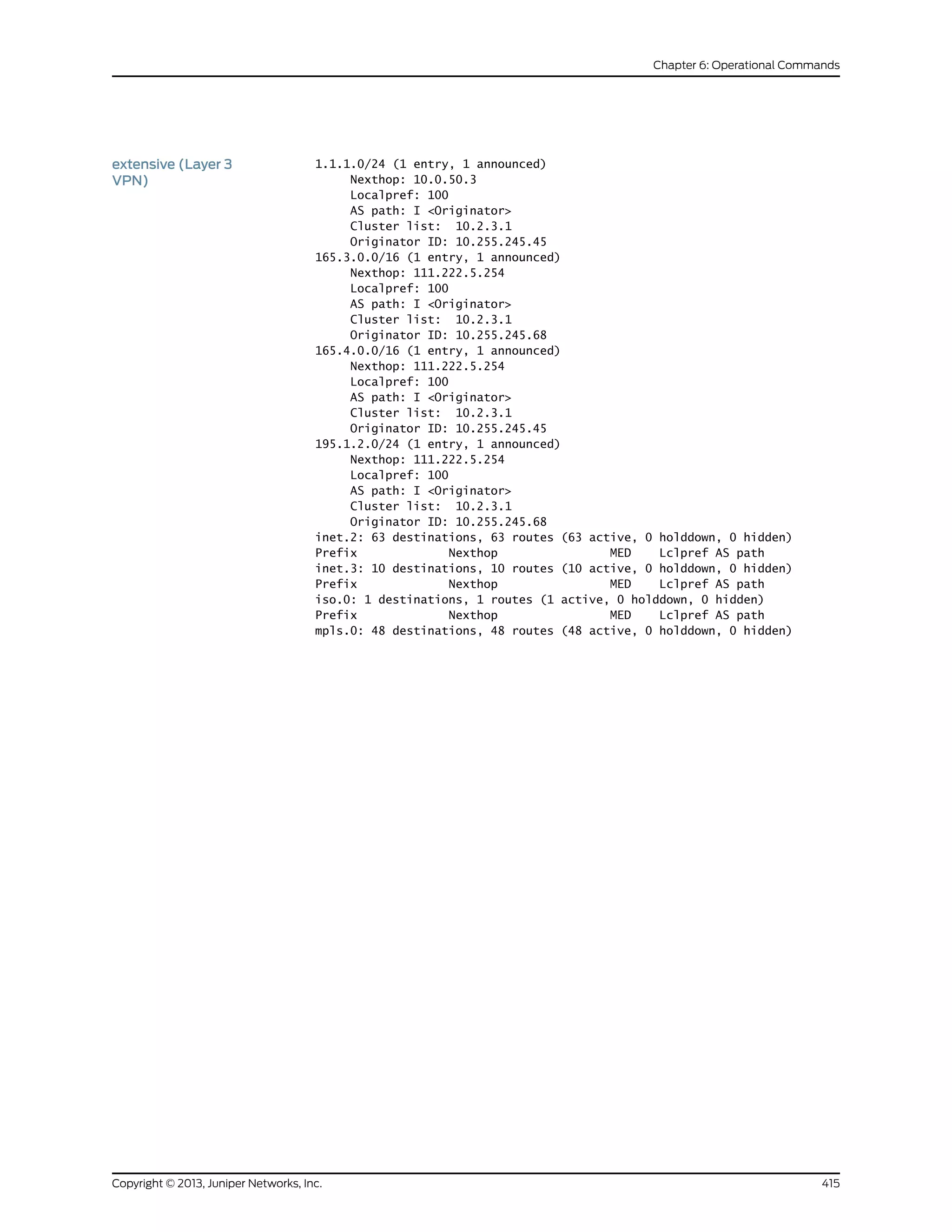
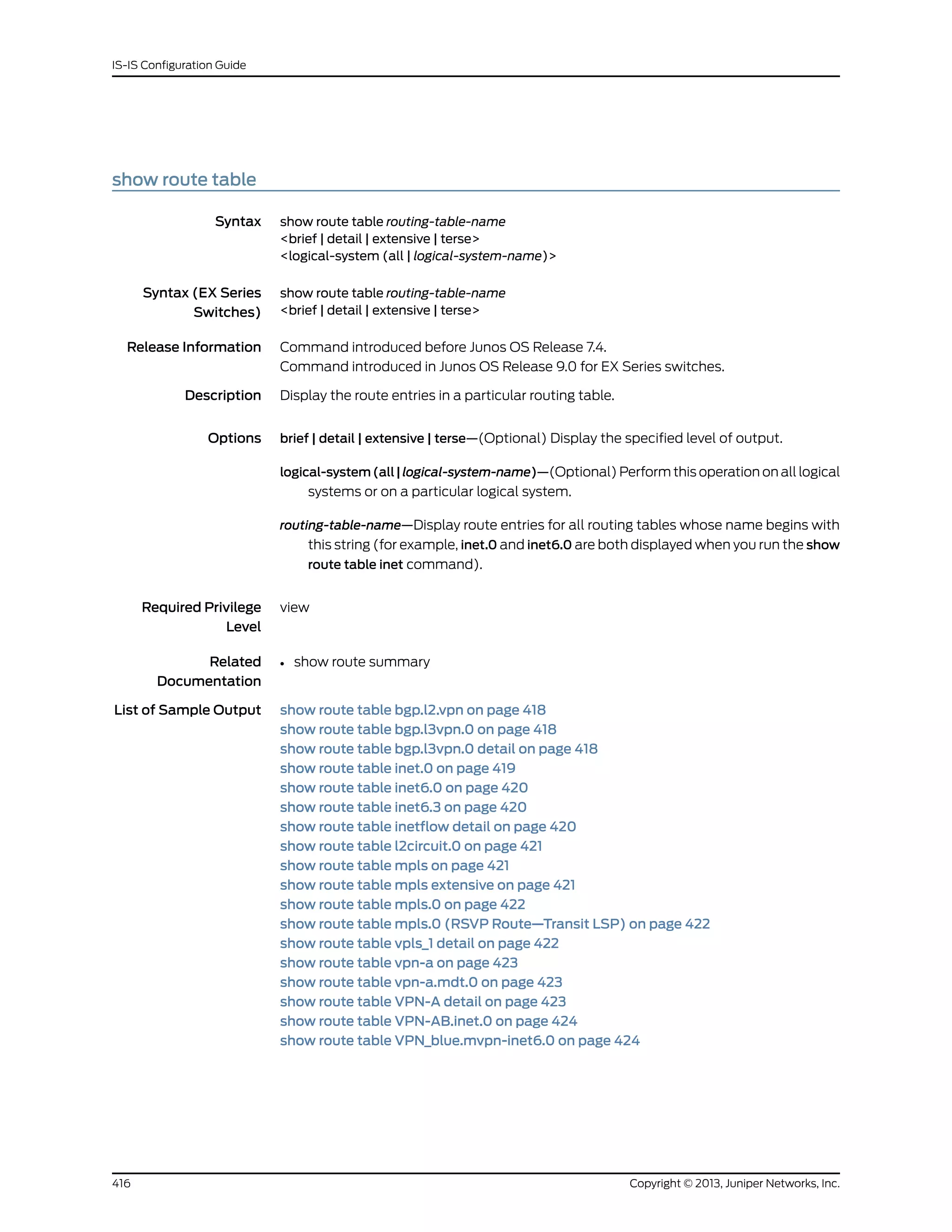

![Sample Output
show route table
bgp.l2.vpn
user@host> show route table bgp.l2.vpn
bgp.l2vpn.0: 1 destinations, 1 routes (1 active, 0 holddown, 0 hidden)
+ = Active Route, - = Last Active, * = Both
192.168.24.1:1:4:1/96
*[BGP/170] 01:08:58, localpref 100, from 192.168.24.1
AS path: I
> to 10.0.16.2 via fe-0/0/1.0, label-switched-path am
show route table
bgp.l3vpn.0
user@host> show route table bgp.l3vpn.0
bgp.l3vpn.0: 2 destinations, 2 routes (2 active, 0 holddown, 0 hidden)
+ = Active Route, - = Last Active, * = Both
10.255.71.15:100:10.255.71.17/32
*[BGP/170] 00:03:59, MED 1, localpref 100, from
10.255.71.15
AS path: I
> via so-2/1/0.0, Push 100020, Push 100011(top)
10.255.71.15:200:10.255.71.18/32
*[BGP/170] 00:03:59, MED 1, localpref 100, from
10.255.71.15
AS path: I
> via so-2/1/0.0, Push 100021, Push 100011(top)
show route table
bgp.l3vpn.0 detail
user@host> show route table bgp.l3vpn.0 detail
bgp.l3vpn.0: 8 destinations, 8 routes (8 active, 0 holddown, 0 hidden)
10.255.245.12:1:4.0.0.0/8 (1 entry, 1 announced)
*BGP Preference: 170/-101
Route Distinguisher: 10.255.245.12:1
Source: 10.255.245.12
Next hop: 192.168.208.66 via fe-0/0/0.0, selected
Label operation: Push 182449
Protocol next hop: 10.255.245.12
Push 182449
Indirect next hop: 863a630 297
State: <Active Int Ext>
Local AS: 35 Peer AS: 35
Age: 12:19 Metric2: 1
Task: BGP_35.10.255.245.12+179
Announcement bits (1): 0-BGP.0.0.0.0+179
AS path: 30 10458 14203 2914 3356 I (Atomic) Aggregator: 3356 4.68.0.11
Communities: 2914:420 target:11111:1 origin:56:78
VPN Label: 182449
Localpref: 100
Router ID: 10.255.245.12
10.255.245.12:1:4.17.225.0/24 (1 entry, 1 announced)
*BGP Preference: 170/-101
Route Distinguisher: 10.255.245.12:1
Source: 10.255.245.12
Next hop: 192.168.208.66 via fe-0/0/0.0, selected
Label operation: Push 182465
Protocol next hop: 10.255.245.12
Push 182465
Copyright © 2013, Juniper Networks, Inc.418
IS-IS Configuration Guide](https://image.slidesharecdn.com/config-guide-routing-is-is-151104131021-lva1-app6891/75/Juniper-MX-Config-guide-routing-is-is-438-2048.jpg)
![Indirect next hop: 863a8f0 305
State: <Active Int Ext>
Local AS: 35 Peer AS: 35
Age: 12:19 Metric2: 1
Task: BGP_35.10.255.245.12+179
Announcement bits (1): 0-BGP.0.0.0.0+179
AS path: 30 10458 14203 2914 11853 11853 11853 6496 6496 6496 6496 6496 6496 I
Communities: 2914:410 target:12:34 target:11111:1 origin:12:34
VPN Label: 182465
Localpref: 100
Router ID: 10.255.245.12
10.255.245.12:1:4.17.226.0/23 (1 entry, 1 announced)
*BGP Preference: 170/-101
Route Distinguisher: 10.255.245.12:1
Source: 10.255.245.12
Next hop: 192.168.208.66 via fe-0/0/0.0, selected
Label operation: Push 182465
Protocol next hop: 10.255.245.12
Push 182465
Indirect next hop: 86bd210 330
State: <Active Int Ext>
Local AS: 35 Peer AS: 35
Age: 12:19 Metric2: 1
Task: BGP_35.10.255.245.12+179
Announcement bits (1): 0-BGP.0.0.0.0+179
AS path: 30 10458 14203 2914 11853 11853 11853 6496 6496 6496 6496 6496
6496 I
Communities: 2914:410 target:12:34 target:11111:1 origin:12:34
VPN Label: 182465
Localpref: 100
Router ID: 10.255.245.12
10.255.245.12:1:4.17.251.0/24 (1 entry, 1 announced)
*BGP Preference: 170/-101
Route Distinguisher: 10.255.245.12:1
Source: 10.255.245.12
Next hop: 192.168.208.66 via fe-0/0/0.0, selected
Label operation: Push 182465
Protocol next hop: 10.255.245.12
Push 182465
Indirect next hop: 86bd210 330
State: <Active Int Ext>
Local AS: 35 Peer AS: 35
Age: 12:19 Metric2: 1
Task: BGP_35.10.255.245.12+179
Announcement bits (1): 0-BGP.0.0.0.0+179
AS path: 30 10458 14203 2914 11853 11853 11853 6496 6496 6496 6496 6496
6496 I
Communities: 2914:410 target:12:34 target:11111:1 origin:12:34
VPN Label: 182465
Localpref: 100
show route table inet.0 user@host> show route table inet.0
inet.0: 12 destinations, 12 routes (11 active, 0 holddown, 1 hidden)
+ = Active Route, - = Last Active, * = Both
0.0.0.0/0 *[Static/5] 00:51:57
> to 111.222.5.254 via fxp0.0
419Copyright © 2013, Juniper Networks, Inc.
Chapter 6: Operational Commands](https://image.slidesharecdn.com/config-guide-routing-is-is-151104131021-lva1-app6891/75/Juniper-MX-Config-guide-routing-is-is-439-2048.jpg)
![1.0.0.1/32 *[Direct/0] 00:51:58
> via at-5/3/0.0
1.0.0.2/32 *[Local/0] 00:51:58
Local
12.12.12.21/32 *[Local/0] 00:51:57
Reject
13.13.13.13/32 *[Direct/0] 00:51:58
> via t3-5/2/1.0
13.13.13.14/32 *[Local/0] 00:51:58
Local
13.13.13.21/32 *[Local/0] 00:51:58
Local
13.13.13.22/32 *[Direct/0] 00:33:59
> via t3-5/2/0.0
127.0.0.1/32 [Direct/0] 00:51:58
> via lo0.0
111.222.5.0/24 *[Direct/0] 00:51:58
> via fxp0.0
111.222.5.81/32 *[Local/0] 00:51:58
Local
show route table
inet6.0
user@host> show route table inet6.0
inet6.0: 3 destinations, 3 routes (3 active, 0 holddown, 0 hidden)
+ = Active Route, - = Last Route, * = Both
fec0:0:0:3::/64 *[Direct/0] 00:01:34
>via fe-0/1/0.0
fec0:0:0:3::/128 *[Local/0] 00:01:34
>Local
fec0:0:0:4::/64 *[Static/5] 00:01:34
>to fec0:0:0:3::ffff via fe-0/1/0.0
show route table
inet6.3
user@router> show route table inet6.3
inet6.3: 2 destinations, 2 routes (2 active, 0 holddown, 0 hidden)
+ = Active Route, - = Last Active, * = Both
::10.255.245.195/128
*[LDP/9] 00:00:22, metric 1
> via so-1/0/0.0
::10.255.245.196/128
*[LDP/9] 00:00:08, metric 1
> via so-1/0/0.0, Push 100008
show route table
inetflow detail
user@host> show route table inetflow detail
inetflow.0: 2 destinations, 2 routes (2 active, 0 holddown, 0 hidden)
10.12.44.1,*/48 (1 entry, 1 announced)
*BGP Preference: 170/-101
Next-hop reference count: 2
State: **Active Ext>
Local AS: 65002 Peer AS: 65000
Age: 4
Task: BGP_65000.10.12.99.5+3792
Announcement bits (1): 0-Flow
AS path: 65000 I
Communities: traffic-rate:0:0
Validation state: Accept, Originator: 10.12.99.5
Via: 10.12.44.0/24, Active
Copyright © 2013, Juniper Networks, Inc.420
IS-IS Configuration Guide](https://image.slidesharecdn.com/config-guide-routing-is-is-151104131021-lva1-app6891/75/Juniper-MX-Config-guide-routing-is-is-440-2048.jpg)
![Localpref: 100
Router ID: 10.255.71.161
10.12.56.1,*/48 (1 entry, 1 announced)
*Flow Preference: 5
Next-hop reference count: 2
State: **Active>
Local AS: 65002
Age: 6:30
Task: RT Flow
Announcement bits (2): 0-Flow 1-BGP.0.0.0.0+179
AS path: I
Communities: 1:1
show route table
l2circuit.0
user@host> show route table l2circuit.0
l2circuit.0: 4 destinations, 4 routes (4 active, 0 holddown, 0 hidden)
+ = Active Route, - = Last Active, * = Both
10.1.1.195:NoCtrlWord:1:1:Local/96
*[L2CKT/7] 00:50:47
> via so-0/1/2.0, Push 100049
via so-0/1/3.0, Push 100049
10.1.1.195:NoCtrlWord:1:1:Remote/96
*[LDP/9] 00:50:14
Discard
10.1.1.195:CtrlWord:1:2:Local/96
*[L2CKT/7] 00:50:47
> via so-0/1/2.0, Push 100049
via so-0/1/3.0, Push 100049
10.1.1.195:CtrlWord:1:2:Remote/96
*[LDP/9] 00:50:14
Discard
show route table mpls user@host> show route table mpls
mpls.0: 4 destinations, 4 routes (4 active, 0 holddown, 0 hidden)
+ = Active Route, - = Last Active, * = Both
0 *[MPLS/0] 00:13:55, metric 1
Receive
1 *[MPLS/0] 00:13:55, metric 1
Receive
2 *[MPLS/0] 00:13:55, metric 1
Receive
1024 *[VPN/0] 00:04:18
to table red.inet.0, Pop
show route table mpls
extensive
user@host> show route table mpls extensive
100000 (1 entry, 1 announced)
TSI:
KRT in-kernel 100000 /36 -> {so-1/0/0.0}
*LDP Preference: 9
Next hop: via so-1/0/0.0, selected
Pop
State: <Active Int>
Age: 29:50 Metric: 1
Task: LDP
Announcement bits (1): 0-KRT
AS path: I
Prefixes bound to route: 10.0.0.194/32
421Copyright © 2013, Juniper Networks, Inc.
Chapter 6: Operational Commands](https://image.slidesharecdn.com/config-guide-routing-is-is-151104131021-lva1-app6891/75/Juniper-MX-Config-guide-routing-is-is-441-2048.jpg)
![show route table
mpls.0
user@host> show route table mpls.0
mpls.0: 11 destinations, 11 routes (11 active, 0 holddown, 0 hidden)
+ = Active Route, - = Last Active, * = Both
0 *[MPLS/0] 00:45:09, metric 1
Receive
1 *[MPLS/0] 00:45:09, metric 1
Receive
2 *[MPLS/0] 00:45:09, metric 1
Receive
100000 *[L2VPN/7] 00:43:04
> via so-0/1/0.1, Pop
100001 *[L2VPN/7] 00:43:03
> via so-0/1/0.2, Pop Offset: 4
100002 *[LDP/9] 00:43:22, metric 1
via so-0/1/2.0, Pop
> via so-0/1/3.0, Pop
100002(S=0) *[LDP/9] 00:43:22, metric 1
via so-0/1/2.0, Pop
> via so-0/1/3.0, Pop
100003 *[LDP/9] 00:43:22, metric 1
> via so-0/1/2.0, Swap 100002
via so-0/1/3.0, Swap 100002
100004 *[LDP/9] 00:43:16, metric 1
via so-0/1/2.0, Swap 100049
> via so-0/1/3.0, Swap 100049
so-0/1/0.1 *[L2VPN/7] 00:43:04
> via so-0/1/2.0, Push 100001, Push 100049(top)
via so-0/1/3.0, Push 100001, Push 100049(top)
so-0/1/0.2 *[L2VPN/7] 00:43:03
via so-0/1/2.0, Push 100000, Push 100049(top) Offset: -4
> via so-0/1/3.0, Push 100000, Push 100049(top) Offset: -4
show route table
mpls.0 (RSVP
Route—Transit LSP)
user@host> show route table mpls.0
mpls.0: 8 destinations, 8 routes (8 active, 0 holddown, 0 hidden)
+ = Active Route, - = Last Active, * = Both
0 *[MPLS/0] 00:37:31, metric 1
Receive
1 *[MPLS/0] 00:37:31, metric 1
Receive
2 *[MPLS/0] 00:37:31, metric 1
Receive
13 *[MPLS/0] 00:37:31, metric 1
Receive
300352 *[RSVP/7/1] 00:08:00, metric 1
> to 8.64.0.106 via ge-1/0/1.0, label-switched-path lsp1_p2p
300352(S=0) *[RSVP/7/1] 00:08:00, metric 1
> to 8.64.0.106 via ge-1/0/1.0, label-switched-path lsp1_p2p
300384 *[RSVP/7/2] 00:05:20, metric 1
> to 8.64.1.106 via ge-1/0/0.0, Pop
300384(S=0) *[RSVP/7/2] 00:05:20, metric 1
> to 8.64.1.106 via ge-1/0/0.0, Pop
showroutetablevpls_1
detail
user@host> show route table vpls_1 detail
vpls_1.l2vpn.0: 1 destinations, 1 routes (1 active, 0 holddown, 0 hidden)
Restart Complete
Copyright © 2013, Juniper Networks, Inc.422
IS-IS Configuration Guide](https://image.slidesharecdn.com/config-guide-routing-is-is-151104131021-lva1-app6891/75/Juniper-MX-Config-guide-routing-is-is-442-2048.jpg)
![1.1.1.11:1000:1:1/96 (1 entry, 1 announced)
*L2VPN Preference: 170/-1
Receive table: vpls_1.l2vpn.0
Next-hop reference count: 2
State: <Active Int Ext>
Age: 4:29:47 Metric2: 1
Task: vpls_1-l2vpn
Announcement bits (1): 1-BGP.0.0.0.0+179
AS path: I
Communities: Layer2-info: encaps:VPLS, control flags:Site-Down
Label-base: 800000, range: 8, status-vector: 0xFF
showroutetablevpn-a user@host> show route table vpn-a
vpn-a.l2vpn.0: 3 destinations, 3 routes (3 active, 0 holddown, 0 hidden)
+ = Active Route, - = Last Active, * = Both
192.168.16.1:1:1:1/96
*[VPN/7] 05:48:27
Discard
192.168.24.1:1:2:1/96
*[BGP/170] 00:02:53, localpref 100, from 192.168.24.1
AS path: I
> to 10.0.16.2 via fe-0/0/1.0, label-switched-path am
192.168.24.1:1:3:1/96
*[BGP/170] 00:02:53, localpref 100, from 192.168.24.1
AS path: I
> to 10.0.16.2 via fe-0/0/1.0, label-switched-path am
show route table
vpn-a.mdt.0
user@host> show route table vpn-a.mdt.0
vpn-a.mdt.0: 3 destinations, 3 routes (3 active, 0 holddown, 0 hidden)
+ = Active Route, - = Last Active, * = Both
1:1:0:10.255.14.216:232.1.1.1/144
*[MVPN/70] 01:23:05, metric2 1
Indirect
1:1:1:10.255.14.218:232.1.1.1/144
*[BGP/170] 00:57:49, localpref 100, from 10.255.14.218
AS path: I
> via so-0/0/0.0, label-switched-path r0e-to-r1
1:1:2:10.255.14.217:232.1.1.1/144
*[BGP/170] 00:57:49, localpref 100, from 10.255.14.217
AS path: I
> via so-0/0/1.0, label-switched-path r0-to-r2
show route table
VPN-A detail
user@host> show route table VPN-A detail
VPN-AB.inet.0: 8 destinations, 8 routes (8 active, 0 holddown, 0 hidden)
10.255.179.9/32 (1 entry, 1 announced)
*BGP Preference: 170/-101
Route Distinguisher: 10.255.179.13:200
Next hop type: Indirect
Next-hop reference count: 5
Source: 10.255.179.13
Next hop type: Router, Next hop index: 732
Next hop: 10.39.1.14 via fe-0/3/0.0, selected
Label operation: Push 299824, Push 299824(top)
Protocol next hop: 10.255.179.13
Push 299824
Indirect next hop: 8f275a0 1048574
423Copyright © 2013, Juniper Networks, Inc.
Chapter 6: Operational Commands](https://image.slidesharecdn.com/config-guide-routing-is-is-151104131021-lva1-app6891/75/Juniper-MX-Config-guide-routing-is-is-443-2048.jpg)
![State: (Secondary Active Int Ext)
Local AS: 1 Peer AS: 1
Age: 3:41:06 Metric: 1 Metric2: 1
Task: BGP_1.10.255.179.13+64309
Announcement bits (2): 0-KRT 1-BGP RT Background
AS path: I
Communities: target:1:200 rte-type:0.0.0.0:1:0
Import Accepted
VPN Label: 299824 TTL Action: vrf-ttl-propagate
Localpref: 100
Router ID: 10.255.179.13
Primary Routing Table bgp.l3vpn.0
show route table
VPN-AB.inet.0
user@host> show route table VPN-AB.inet.0
VPN-AB.inet.0: 8 destinations, 8 routes (8 active, 0 holddown, 0 hidden)
+ = Active Route, - = Last Active, * = Both
10.39.1.0/30 *[OSPF/10] 00:07:24, metric 1
> via so-7/3/1.0
10.39.1.4/30 *[Direct/0] 00:08:42
> via so-5/1/0.0
10.39.1.6/32 *[Local/0] 00:08:46
Local
10.255.71.16/32 *[Static/5] 00:07:24
> via so-2/0/0.0
10.255.71.17/32 *[BGP/170] 00:07:24, MED 1, localpref 100, from
10.255.71.15
AS path: I
> via so-2/1/0.0, Push 100020, Push 100011(top)
10.255.71.18/32 *[BGP/170] 00:07:24, MED 1, localpref 100, from
10.255.71.15
AS path: I
> via so-2/1/0.0, Push 100021, Push 100011(top)
10.255.245.245/32 *[BGP/170] 00:08:35, localpref 100
AS path: 2 I
> to 10.39.1.5 via so-5/1/0.0
10.255.245.246/32 *[OSPF/10] 00:07:24, metric 1
> via so-7/3/1.0
show route table
VPN_blue.mvpn-inet6.0
user@host> show route table VPN_blue.mvpn-inet6.0
vpn_blue.mvpn-inet6.0: 6 destinations, 6 routes (6 active, 0 holddown, 0 hidden)
+ = Active Route, - = Last Active, * = Both
1:10.255.2.202:65535:10.255.2.202/432
*[BGP/170] 00:02:37, localpref 100, from 10.255.2.202
AS path: I
> via so-0/1/3.0
1:10.255.2.203:65535:10.255.2.203/432
*[BGP/170] 00:02:37, localpref 100, from 10.255.2.203
AS path: I
> via so-0/1/0.0
1:10.255.2.204:65535:10.255.2.204/432
*[MVPN/70] 00:57:23, metric2 1
Indirect
5:10.255.2.202:65535:128:::192.168.90.2:128:ffff::1/432
*[BGP/170] 00:02:37, localpref 100, from 10.255.2.202
AS path: I
> via so-0/1/3.0
6:10.255.2.203:65535:65000:128:::10.12.53.12:128:ffff::1/432
*[PIM/105] 00:02:37
Copyright © 2013, Juniper Networks, Inc.424
IS-IS Configuration Guide](https://image.slidesharecdn.com/config-guide-routing-is-is-151104131021-lva1-app6891/75/Juniper-MX-Config-guide-routing-is-is-444-2048.jpg)
![Multicast (IPv6)
7:10.255.2.202:65535:65000:128:::192.168.90.2:128:ffff::1/432
*[MVPN/70] 00:02:37, metric2 1
Indirect
425Copyright © 2013, Juniper Networks, Inc.
Chapter 6: Operational Commands](https://image.slidesharecdn.com/config-guide-routing-is-is-151104131021-lva1-app6891/75/Juniper-MX-Config-guide-routing-is-is-445-2048.jpg)
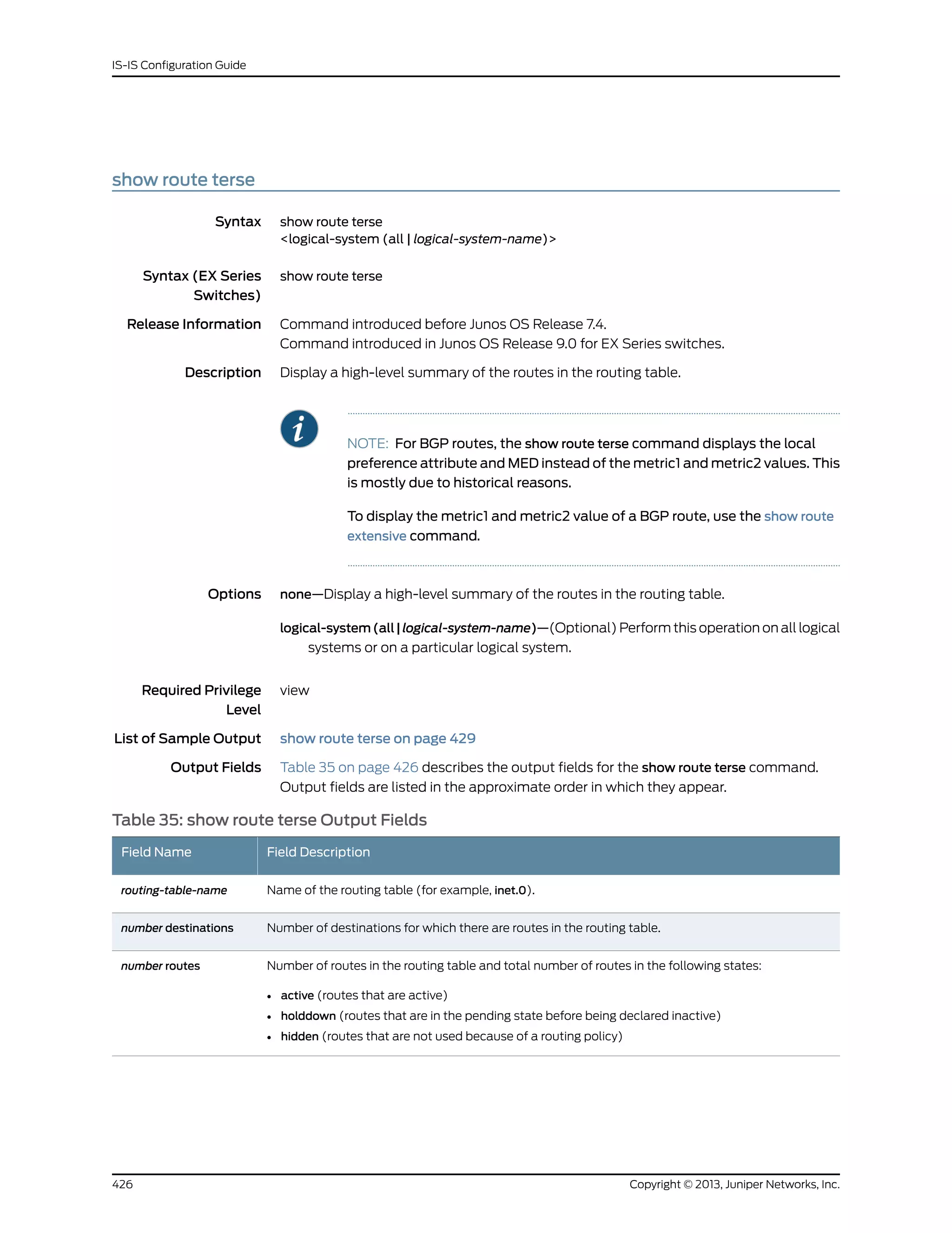
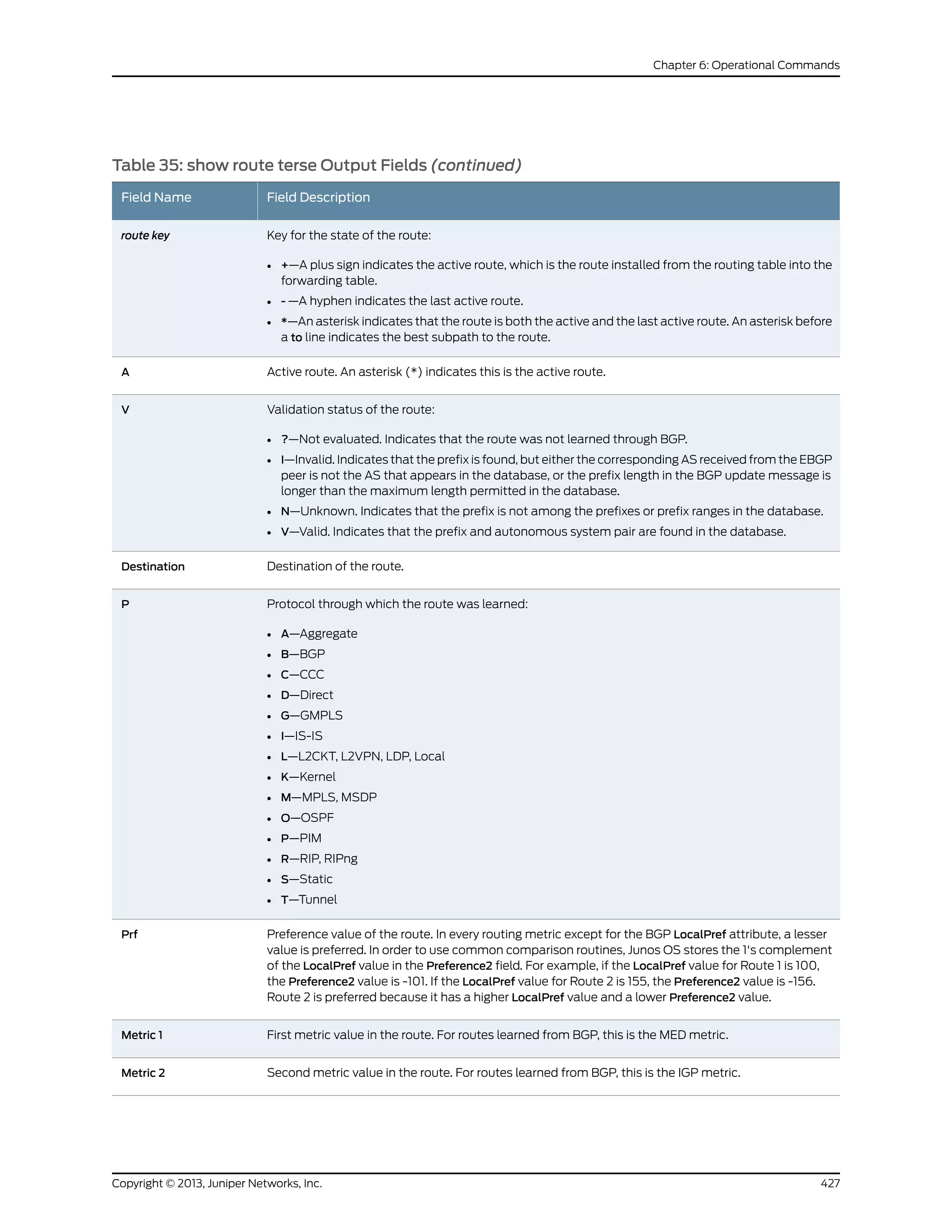
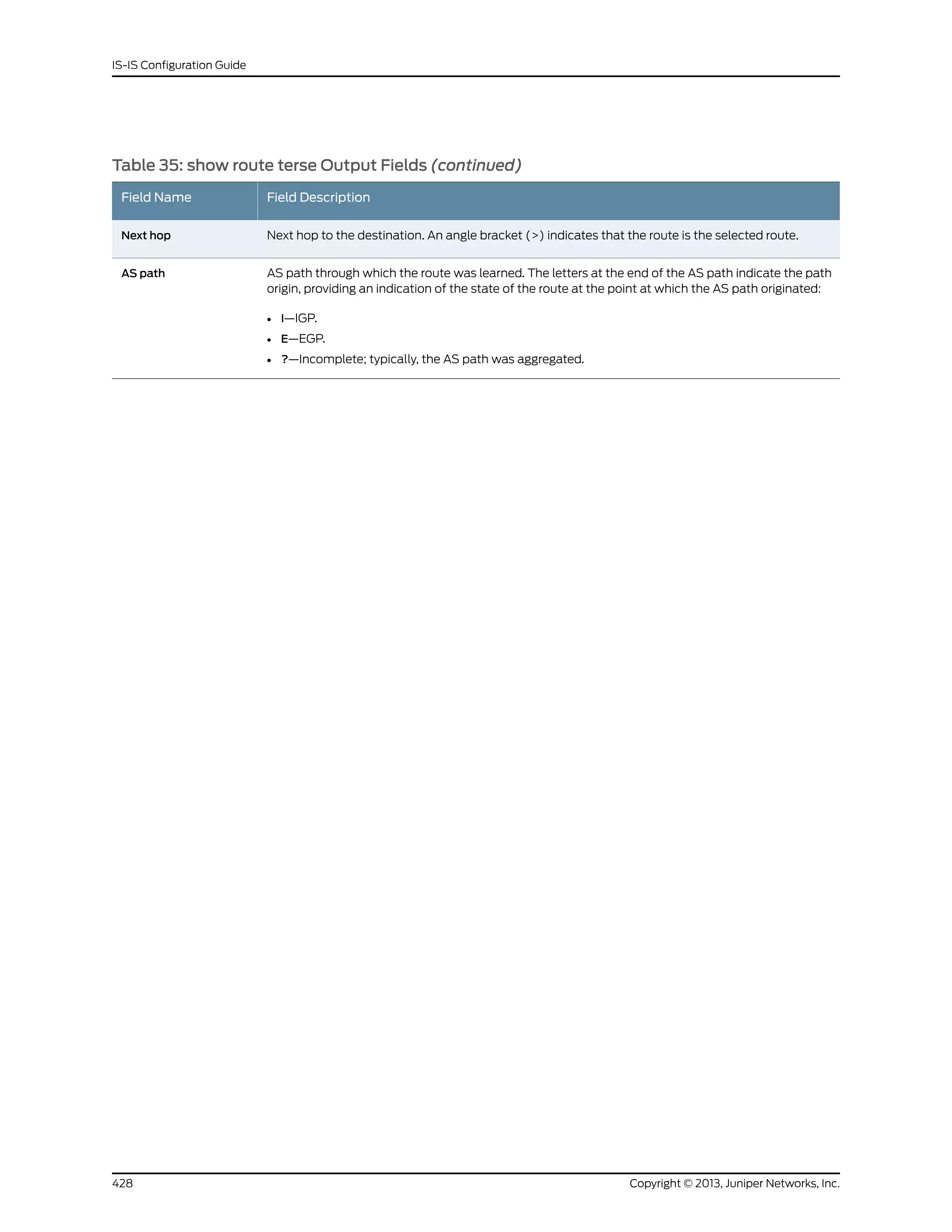
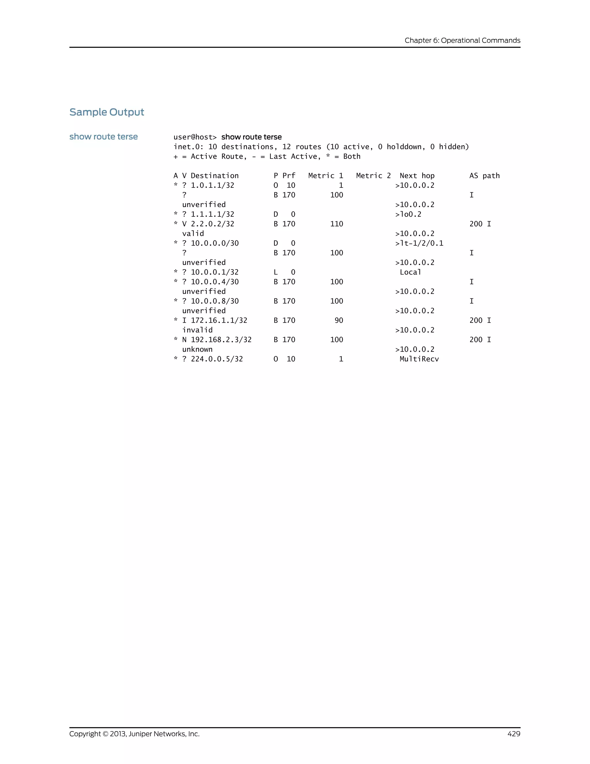
![Sample Output
test policy user@host> test policy test-statics 3.0.0.1/8
inet.0: 44 destinations, 44 routes (44 active, 0 holddown, 0 hidden)
Prefixes passing policy:
3.0.0.0/8 *[BGP/170] 16:22:46, localpref 100, from 10.255.255.41
AS Path: 50888 I
> to 10.11.4.32 via en0.2, label-switched-path l2
3.3.3.1/32 *[IS-IS/18] 2d 00:21:46, metric 0, tag 2
> to 10.0.4.7 via fxp0.0
3.3.3.2/32 *[IS-IS/18] 2d 00:21:46, metric 0, tag 2
> to 10.0.4.7 via fxp0.0
3.3.3.3/32 *[IS-IS/18] 2d 00:21:46, metric 0, tag 2
> to 10.0.4.7 via fxp0.0
3.3.3.4/32 *[IS-IS/18] 2d 00:21:46, metric 0, tag 2
> to 10.0.4.7 via fxp0.0
Policy test-statics: 5 prefixes accepted, 0 prefixes rejected
431Copyright © 2013, Juniper Networks, Inc.
Chapter 6: Operational Commands](https://image.slidesharecdn.com/config-guide-routing-is-is-151104131021-lva1-app6891/75/Juniper-MX-Config-guide-routing-is-is-451-2048.jpg)

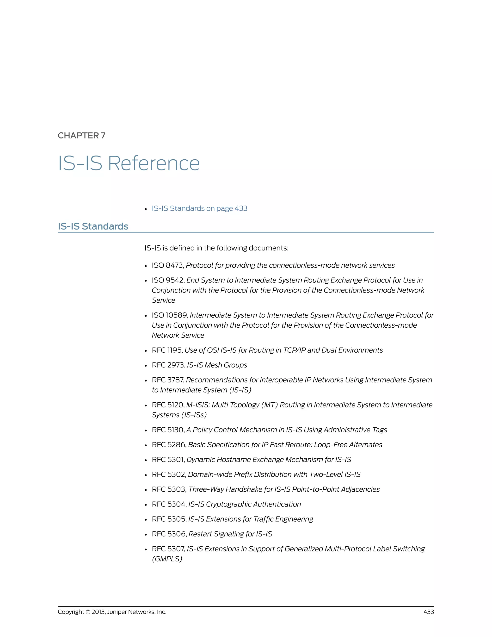

![CHAPTER 8
IS-IS Troubleshooting
• Checklist for Verifying the IS-IS Protocol and Adjacencies on page 437
• Verifying the IS-IS Protocol on page 438
• Verify the IS-IS Configuration on a Router in a Network on page 449
• Display the Status of IS-IS Adjacencies on page 457
• Verify IS-IS Adjacencies and Interfaces on page 466
• Display Detailed IS-IS Protocol Information on page 468
• Analyze IS-IS-Link State Packets in Detail on page 470
• Display Sent or Received IS-IS Protocol Packets on page 472
Checklist for Verifying the IS-IS Protocol and Adjacencies
Purpose Table 36 on page 437 provides links and commands for verifying the IS-IS protocol and
adjacencies.
ActionTable 36: Checklist for Verifying the IS-IS Protocol and Adjacencies
Command or ActionTasks
“Verifying the IS-IS Configuration on a Router in a Network” on page 449
[edit protocols isis] show
[edit protocols isis] run show isis interface
[edit] edit interfaces
[edit interfaces] show
1. Check the Configuration of a Level 1/Level 2 Router on page 450
[edit protocols isis] show
[edit protocols isis] run show isis interface
[edit] edit interfaces
[edit interfaces] show
2. Check the Configuration of a Level 1 Router on page 453
[edit protocols isis] show
[edit protocols isis] run show isis interface
[edit] edit interfaces
[edit interfaces] show
3. Check the Configuration of a Level 2 Router on page 455
“Displaying the Status of IS-IS Adjacencies” on page 457
show isis adjacency1. Verifying Adjacent Routers on page 458
437Copyright © 2013, Juniper Networks, Inc.](https://image.slidesharecdn.com/config-guide-routing-is-is-151104131021-lva1-app6891/75/Juniper-MX-Config-guide-routing-is-is-457-2048.jpg)
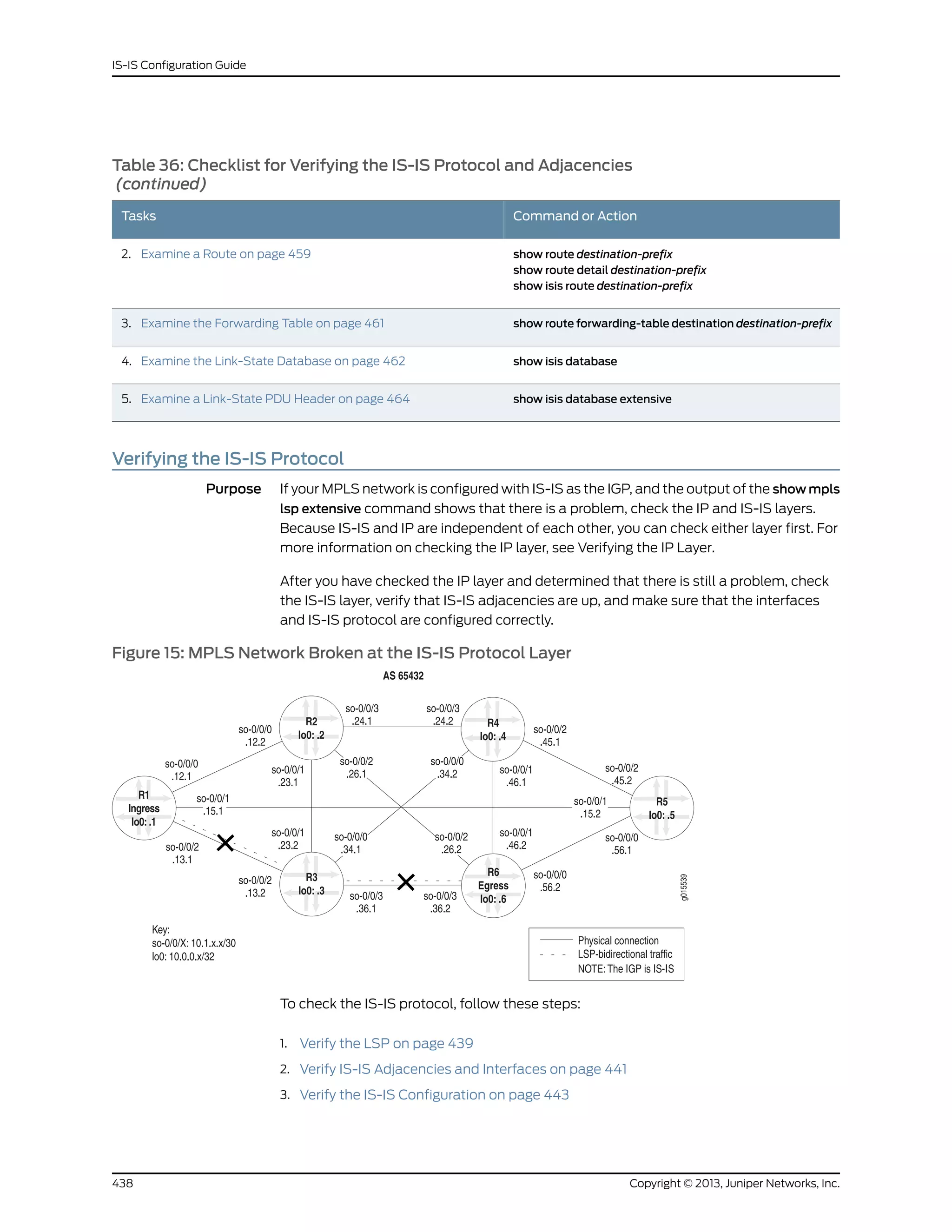
![Sample Output 1
user@R1> show mpls lsp extensive
Ingress LSP: 1 sessions
10.0.0.6
From: 10.0.0.1, State: Dn, ActiveRoute: 0 , LSPname: R1-to-R6
ActivePath: (none)
LoadBalance: Random
Encoding type: Packet, Switching type: Packet, GPID: IPv4
Primary State: Dn
24 Oct 21 13:48:01 No Route toward dest [3 times]
23 Oct 21 13:47:44 Deselected as active
22 Oct 21 13:47:43 No Route toward dest[2 times]
21 Oct 21 13:47:43 ResvTear received
20 Oct 21 13:47:43 Down
19 Oct 21 13:47:43 10.1.13.2: No Route toward dest[2 times]
18 Oct 21 13:47:38 Record Route: 10.1.13.2 10.1.36.2
[...Output truncated...]
Created: Tue Oct 19 21:22:53 2004
Total 1 displayed, Up 0, Down 1
Egress LSP: 0 sessions
Total 0 displayed, Up 0, Down 0
Transit LSP: 0 sessions
Total 0 displayed, Up 0, Down 0
Sample Output 2
user@R3> show mpls lsp extensive
Ingress LSP: 0 sessions
Total 0 displayed, Up 0, Down 0
Egress LSP: 0 sessions
Total 0 displayed, Up 0, Down 0
Transit LSP: 0 sessions
Total 0 displayed, Up 0, Down 0
Sample Output 3
user@R6> show mpls lsp extensive
Ingress LSP: 1 sessions
10.0.0.1
From: 10.0.0.6, State: Dn, ActiveRoute: 0 , LSPname: R6-to-R1
ActivePath: (none)
LoadBalance: Random
Encoding type: Packet, Switching type: Packet, GPID: IPv4
Primary State: Dn
Will be enqueued for recomputation in 3 second(s).
13 Oct 21 14:23:33 CSPF failed: no route toward 10.0.0.1[90 times]
12 Oct 21 13:39:56 Deselected as active
11 Oct 21 13:39:56 CSPF: could not determine self
[...Output truncated...]
Created: Tue Oct 19 22:28:30 2004
Total 1 displayed, Up 0, Down 1
Copyright © 2013, Juniper Networks, Inc.440
IS-IS Configuration Guide](https://image.slidesharecdn.com/config-guide-routing-is-is-151104131021-lva1-app6891/75/Juniper-MX-Config-guide-routing-is-is-460-2048.jpg)
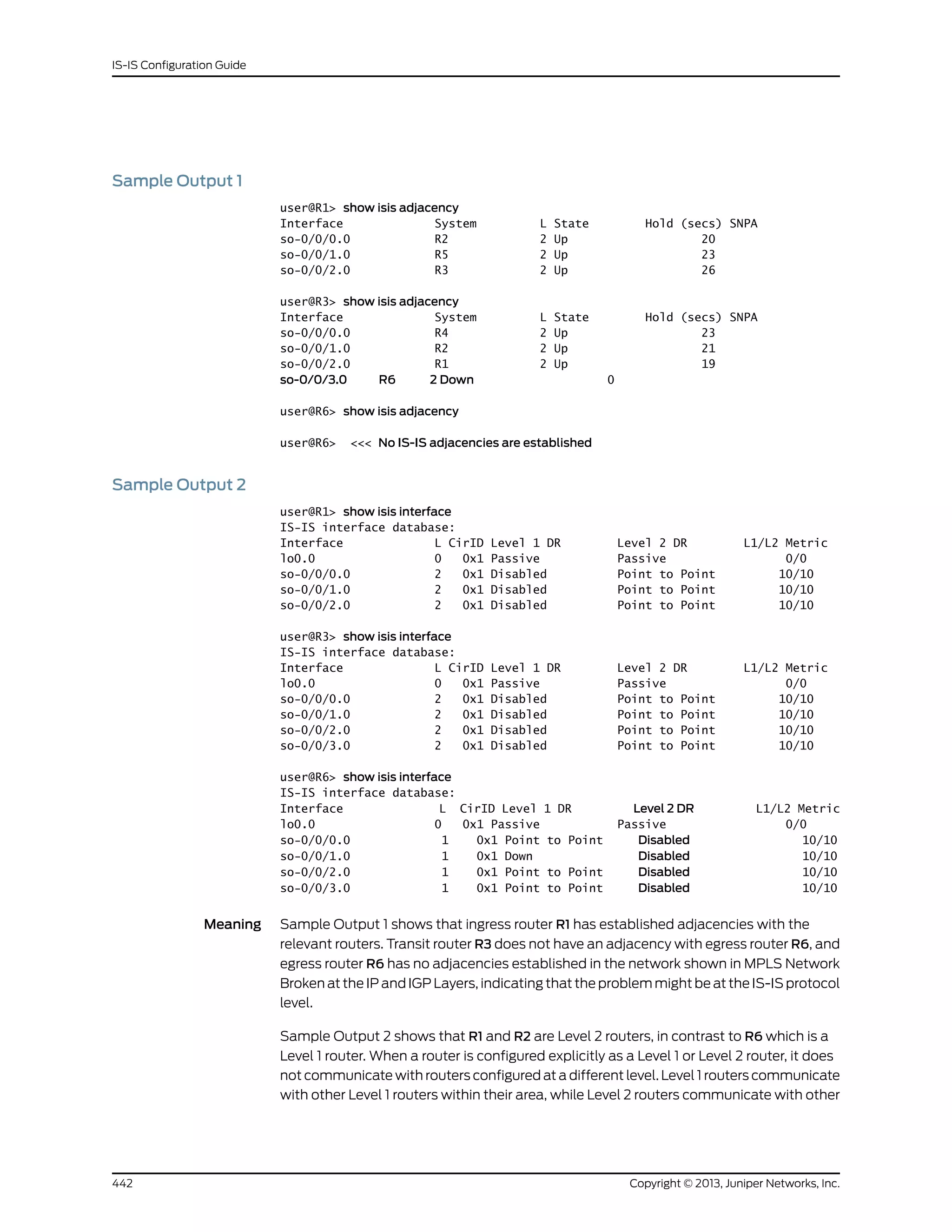
![Level 2 routers, and towards other autonomous systems. Because all the routers in this
network are configured for Level 2, they cannot form an adjacency with R6, which is
incorrectly configured as a Level 1 router.
Verify the IS-IS Configuration
Purpose When you have determined that the problem is probably at the IS-IS protocol level, check
the IS-IS configuration of the routers in your network.
Action To verify the IS-IS configuration, enter the following command from the relevant routers:
user@host> show configuration protocols isis
Sample Output
user@R1> show configuration protocols isis
level 1 disable;
interface so-0/0/0.0;
interface so-0/0/1.0;
interface so-0/0/2.0;
interface lo0.0; {
passive
user@R3> show configuration protocols isis
level 1 disable;
interface all {
level 2 metric 10;
}
interface fxp0.0 {
disable;
}
interface lo0.0; {
passive
user@R6> show configuration protocols isis
level 2 disable; <<< Incorrect level disabled
interface all {
level 2 metric 10;
}
interface fxp0.0 {
disable;
}
interface lo0.0; {
passive
Meaning The sample output shows that R6 has Level 2 disabled, while R1 and R3 have Level 1
disabled. For IS-IS adjacencies to establish, routers need to be at the same level. Another
common configuration error is to omit the loopback (lo0) interface from the configuration
at the [edit protocols isis] hierarchy level. IS-IS does not function correctly if the loopback
(lo0) interface is not configured at this level. In addition, including the passive statement
ensures that protocols are not run over the loopback (lo0) interface and the loopback
(lo0) interface is advertised correctly throughout the network.
443Copyright © 2013, Juniper Networks, Inc.
Chapter 8: IS-IS Troubleshooting](https://image.slidesharecdn.com/config-guide-routing-is-is-151104131021-lva1-app6891/75/Juniper-MX-Config-guide-routing-is-is-463-2048.jpg)
![Take Appropriate Action
Problem Depending on the error you encountered in your investigation, you must take the
appropriate action to correct the problem. In the example below, the routers are configured
to function at different levels of the IS-IS protocol.
Solution To correct the error in this example, enter the following commands:
user@R6> edit
[edit]
user@R6> edit protocols isis
[edit protocols isis]
user@R6# show
user@R6# delete level 2
user@R6# set level 1 disable
user@R6# show
user@R6# commit
user@R6# run show isis adjacency
Copyright © 2013, Juniper Networks, Inc.444
IS-IS Configuration Guide](https://image.slidesharecdn.com/config-guide-routing-is-is-151104131021-lva1-app6891/75/Juniper-MX-Config-guide-routing-is-is-464-2048.jpg)
![Sample Output user@R6> edit
Entering configuration mode
[edit]
user@R6# edit protocols isis
[edit protocols isis]
user@R6# show
level 2 disable;
interface all {
level 2 metric 10;
}
interface fxp0.0 {
disable;
}
interface lo0.0; {
passive
[edit protocols isis]
user@R6# delete level 2
[edit protocols isis]
user@R6# set level 1 disable
[edit protocols isis]
user@R6# show
level 1 disable;
interface all {
level 2 metric 10;
}
interface fxp0.0 {
disable;
}
interface lo0.0; {
passive
[edit protocols isis]
user@R6# commit
commit complete
[edit protocols isis]
user@R6# run show isis adjacency
Interface System L State Hold (secs) SNPA
so-0/0/0.0 R5 2 Up 22
so-0/0/1.0 R4 2 Up 22
so-0/0/2.0 R2 2 Up 22
so-0/0/3.0 R3 2 Up 22
Meaning The sample output shows that the configuration error on egress router R6 has been
corrected and IS-IS adjacencies are now established.
Verify the LSP Again
Purpose After taking the appropriate action to correct the error, the LSP needs to be checked
again to confirm that the problem in the RSVP layer has been resolved.
Action To verify that the LSP is up and traversing the network as expected, enter the following
command from the ingress, egress, and transit routers:
445Copyright © 2013, Juniper Networks, Inc.
Chapter 8: IS-IS Troubleshooting](https://image.slidesharecdn.com/config-guide-routing-is-is-151104131021-lva1-app6891/75/Juniper-MX-Config-guide-routing-is-is-465-2048.jpg)

![Sample Output 1
user@R1> show mpls lsp extensive
Ingress LSP: 1 sessions
10.0.0.6
From: 10.0.0.1, State: Up, ActiveRoute: 1 , LSPname: R1-to-R6
ActivePath: (primary)
LoadBalance: Random
Encoding type: Packet, Switching type: Packet, GPID: IPv4
*Primary State: Up
Computed ERO (S [L] denotes strict [loose] hops): (CSPF metric: 20)
10.1.13.2 S 10.1.36.2 S
Received RRO (ProtectionFlag 1=Available 2=InUse 4=B/W 8=Node 10=SoftPreempt):
10.1.13.2 10.1.36.2
5 Oct 21 15:52:07 Selected as active path
4 Oct 21 15:52:07 Record Route: 10.1.13.2 10.1.36.2
3 Oct 21 15:52:07 Up
2 Oct 21 15:52:07 Originate Call
1 Oct 21 15:52:07 CSPF: computation result accepted
Created: Thu Oct 21 15:52:06 2004
Total 1 displayed, Up 1 , Down 0
Egress LSP: 1 sessions
10.0.0.1
From: 10.0.0.6, LSPstate: Up, ActiveRoute: 0
LSPname: R6-to-R1 , LSPpath: Primary
Suggested label received: -, Suggested label sent: -
Recovery label received: -, Recovery label sent: -
Resv style: 1 FF, Label in: 3, Label out: -
Time left: 142, Since: Thu Oct 21 15:41:59 2004
Tspec: rate 0bps size 0bps peak Infbps m 20 M 1500
Port number: sender 2 receiver 39082 protocol 0
PATH rcvfrom: 10.1.13.2 (so-0/0/2.0) 17 pkts
Adspec: received MTU 1500
PATH sentto: localclient
RESV rcvfrom: localclient
Record route: 10.1.36.2 10.1.13.2 <self>
Total 1 displayed, Up 1 , Down 0
Transit LSP: 0 sessions
Total 0 displayed, Up 0, Down 0
Sample Output 2
user@R3> show mpls lsp extensive
Ingress LSP: 0 sessions
Total 0 displayed, Up 0, Down 0
Egress LSP: 0 sessions
Total 0 displayed, Up 0, Down 0
Transit LSP: 2 sessions
10.0.0.1
From: 10.0.0.6, LSPstate: Up, ActiveRoute: 1
LSPname: R6-to-R1 , LSPpath: Primary
Suggested label received: -, Suggested label sent: -
447Copyright © 2013, Juniper Networks, Inc.
Chapter 8: IS-IS Troubleshooting](https://image.slidesharecdn.com/config-guide-routing-is-is-151104131021-lva1-app6891/75/Juniper-MX-Config-guide-routing-is-is-467-2048.jpg)
![Recovery label received: -, Recovery label sent: 3
Resv style: 1 FF, Label in: 100528, Label out: 3
Time left: 125, Since: Thu Oct 21 15:29:26 2004
Tspec: rate 0bps size 0bps peak Infbps m 20 M 1500
Port number: sender 2 receiver 39082 protocol 0
PATH rcvfrom: 10.1.36.2 (so-0/0/3.0) 17 pkts
Adspec: received MTU 1500 sent MTU 1500
PATH sentto: 10.1.13.1 (so-0/0/2.0) 17 pkts
RESV rcvfrom: 10.1.13.1 (so-0/0/2.0) 17 pkts
Explct route: 10.1.13.1
Record route: 10.1.36.2 <self> 10.1.13.1
10.0.0.6
From: 10.0.0.1, LSPstate: Up, ActiveRoute: 1
LSPname: R1-to-R6 , LSPpath: Primary
Suggested label received: -, Suggested label sent: -
Recovery label received: -, Recovery label sent: 3
Resv style: 1 FF, Label in: 100544, Label out: 3
Time left: 147, Since: Thu Oct 21 15:39:33 2004
Tspec: rate 0bps size 0bps peak Infbps m 20 M 1500
Port number: sender 1 receiver 47963 protocol 0
PATH rcvfrom: 10.1.13.1 (so-0/0/2.0) 4 pkts
Adspec: received MTU 1500 sent MTU 1500
PATH sentto: 10.1.36.2 (so-0/0/3.0) 4 pkts
RESV rcvfrom: 10.1.36.2 (so-0/0/3.0) 4 pkts
Explct route: 10.1.36.2
Record route: 10.1.13.1 <self> 10.1.36.2
Total 2 displayed, Up 2, Down 0
Sample Output 3
user@R6> show mpls lsp extensive
Ingress LSP: 1 sessions
10.0.0.1
From: 10.0.0.6, State: Up, ActiveRoute: 1, LSPname: R6-to-R1
ActivePath: (primary)
LoadBalance: Random
Encoding type: Packet, Switching type: Packet, GPID: IPv4
*Primary State: Up
Computed ERO (S [L] denotes strict [loose] hops): (CSPF metric: 20)
10.1.36.1 S 10.1.13.1 S
Received RRO (ProtectionFlag 1=Available 2=InUse 4=B/W 8=Node 10=SoftPreempt):
10.1.36.1 10.1.13.1
18 Oct 21 15:34:18 Selected as active path
17 Oct 21 15:34:17 Record Route: 10.1.36.1 10.1.13.1
16 Oct 21 15:34:17 Up
15 Oct 21 15:34:17 Originate Call
14 Oct 21 15:34:17 CSPF: computation result accepted
[...Output truncated...]
Created: Tue Oct 19 22:28:30 2004
Total 1 displayed, Up 1, Down 0
Egress LSP: 1 sessions
10.0.0.6
From: 10.0.0.1, LSPstate: Up, ActiveRoute: 0
LSPname: R1-to-R6 , LSPpath: Primary
Suggested label received: -, Suggested label sent: -
Recovery label received: -, Recovery label sent: -
Copyright © 2013, Juniper Networks, Inc.448
IS-IS Configuration Guide](https://image.slidesharecdn.com/config-guide-routing-is-is-151104131021-lva1-app6891/75/Juniper-MX-Config-guide-routing-is-is-468-2048.jpg)
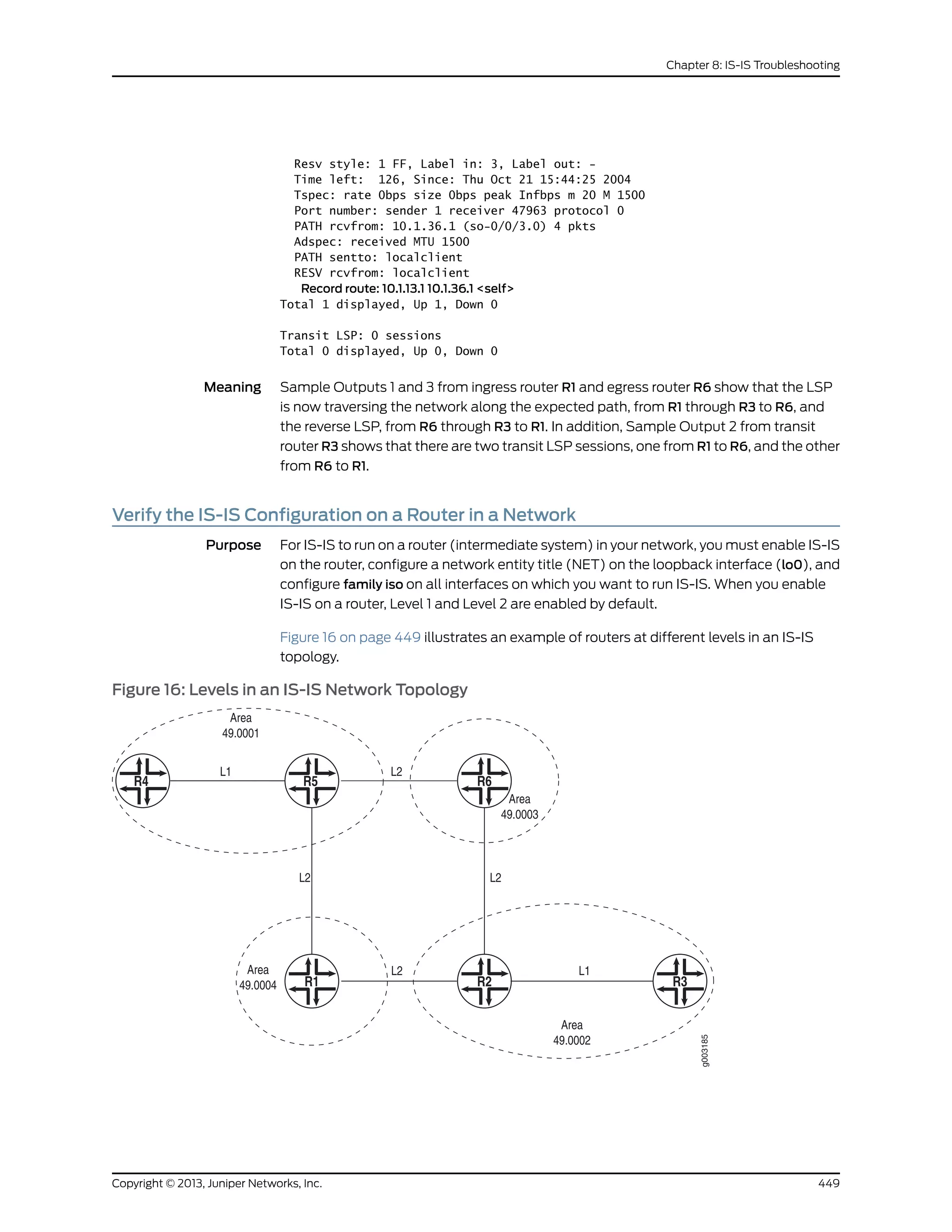
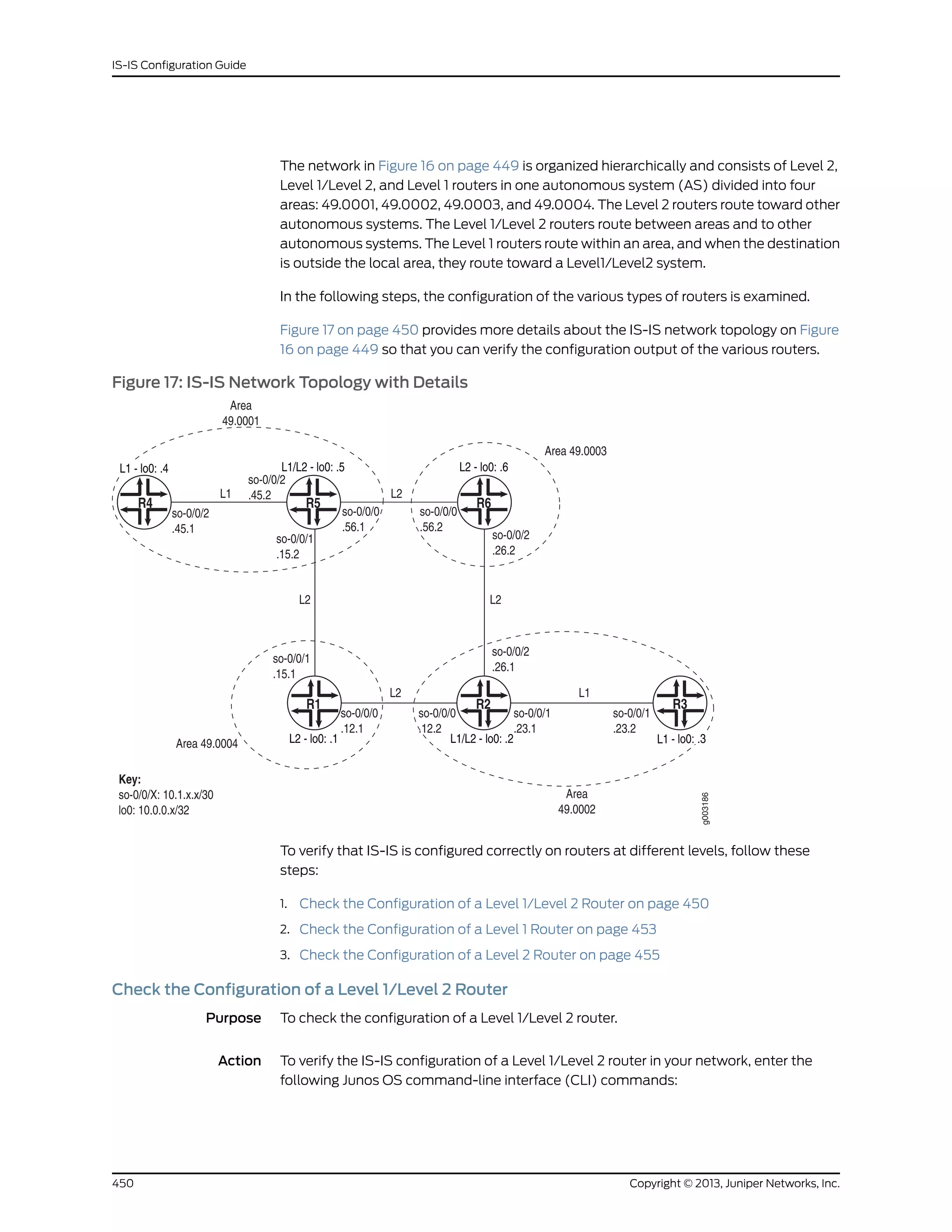
![user@host# [edit protocols isis] show
user@host# [edit protocols isis]run show isis interface
user@host# [edit] edit interfaces
user@host# [edit interfaces] show
The following output is for an IS-IS configuration on R2, a Level 1/Level 2 router in the
network shown in Figure 16 on page 449:
451Copyright © 2013, Juniper Networks, Inc.
Chapter 8: IS-IS Troubleshooting](https://image.slidesharecdn.com/config-guide-routing-is-is-151104131021-lva1-app6891/75/Juniper-MX-Config-guide-routing-is-is-471-2048.jpg)
![Sample Output
[edit protocols isis]
user@R2# show
interface so-0/0/0.0 {
level 2 metric 10;
level 1 disable;
}
interface so-0/0/1.0 {
level 2 disable;
level 1 metric 10;
}
interface so-0/0/2.0 {
level 2 metric 10;
level 1 disable;
}
interface fxp0.0 {
disable;
}
interface lo0.0;
[edit protocols isis]
user@R2# run show isis interface
IS-IS interface database:
Interface L CirID Level 1 DR Level 2 DR L1/L2 Metric
lo0.0 0 0x1 Passive Passive 0/0
so-0/0/0.0 2 0x1 Disabled Point to Point 10/10
so-0/0/1.0 3 0x1 Point to Point Point to Point 10/10
so-0/0/2.0 2 0x1 Disabled Point to Point 10/10
[edit interfaces]
user@R2# show
so-0/0/0 {
unit 0 {
family inet {
address 10.1.12.2/30;
}
family iso;
}
}
so-0/0/1 {
unit 0 {
family inet {
address 10.1.23.1/30;
}
family iso;
}
}
so-0/0/2 {
unit 0 {
family inet {
address 10.1.26.1/30;
}
family iso;
}
}
lo0 {
unit 0 {
family inet {
address 10.0.0.2/32;
Copyright © 2013, Juniper Networks, Inc.452
IS-IS Configuration Guide](https://image.slidesharecdn.com/config-guide-routing-is-is-151104131021-lva1-app6891/75/Juniper-MX-Config-guide-routing-is-is-472-2048.jpg)
![}
family iso {
address 49.0002.1000.0000.0002.00;
}
}
}
Meaning The sample output shows a basic configuration of IS-IS on R2, a Level 1/Level 2 router.
The basic configuration is at the [edit protocols isis] and [edit interfaces] hierarchy levels.
At the [edit protocols isis] level, five interfaces are included: so-0/0/0, so-0/0/1, so-0/0/2,
fxp0, and the loopback (lo0) interface. Two interfaces, so-0/0/0.0 and so-0/0/2.0, have
Level 1 disabled, making them Level 2 interfaces. One interface, so-0/0/1.0, has Level 2
disabled, making it a Level 1 interface. The management interface (fxp0) is disabled so
that IS-IS packets are not sent over it, and the loopback interface (lo0) is included because
it becomes a point of connection from the router to the IS-IS network.
At the [edit interfaces] hierarchy level, all of the interfaces included in the [edit protocols
isis] hierarchy level are configured with family iso, and the loopback (lo0) interface is
configured with the NET address 49.0002.1000.0000.0002.00. Every router in an IS-IS
network must have at least one NET address that identifies a point of connection to the
IS-IS network. The NET address is generally configured on the loopback (lo0) interface.
Routers that participate in multiple areas can have multiple NET addresses.
See the Junos Routing Protocols Configuration Guide for more information on configuring
IS-IS on a router.
Check the Configuration of a Level 1 Router
Purpose To check the configuration of a Level 1 router.
Action To check the configuration of a Level 1 router, enter the following CLI commands:
user@host# [edit protocols isis] show
user@host# [edit protocols isis] run show isis interface
user@host# [edit] edit interfaces
user@host# [edit interfaces] show
The following sample output is for R4, a Level 1 router in the network shown in Figure 16
on page 449:
453Copyright © 2013, Juniper Networks, Inc.
Chapter 8: IS-IS Troubleshooting](https://image.slidesharecdn.com/config-guide-routing-is-is-151104131021-lva1-app6891/75/Juniper-MX-Config-guide-routing-is-is-473-2048.jpg)
![Sample Output
[edit protocols isis]
user@R4# show
level 2 disable;
interface so-0/0/2.0 {
level 1 metric 10;
}
interface fxp0.0 {
disable;
}
interface lo0.0;
[edit protocols isis]
user@R4# run show isis interface
IS-IS interface database:
Interface L CirID Level 1 DR Level 2 DR L1/L2 Metric
lo0.0 0 0x1 Passive Passive 0/0
so-0/0/2.0 1 0x1 Point to Point Disabled 10/10
[edit interfaces]
user@R4# show
so-0/0/2 {
unit 0 {
family inet {
address 10.1.45.1/30;
}
family iso;
}
}
lo0 {
unit 0 {
family inet {
address 10.0.0.4/32;
}
family iso {
address 49.0001.1000.0000.0004.00;
}
}
}
Meaning The sample output shows a basic configuration of IS-IS on R4, a Level 1 router. The basic
configuration is at the [edit protocols isis] and [edit interfaces] hierarchy levels.
At the [edit protocols isis] hierarchy level, three interfaces are included: so-0/0/2.0, fxp0,
and the loopback (lo0) interface. Level 2 is disabled on the router, making it a Level 1
router that sends packets within its local area, 49.0001. When a packet destination is
outside the local area, R4 establishes an adjacency with the nearest Level 1/Level 2 router
(R5) that forwards the packets. For more information on adjacencies, see “Displaying
the Status of IS-IS Adjacencies” on page 457.
One interface, so-0/0/2.0, is configured for IS-IS. The management interface (fxp0) is
disabled so that IS-IS packets are not sent over it, and the loopback interface (lo0) is
included because it becomes a point of connection from the router to the IS-IS network.
Copyright © 2013, Juniper Networks, Inc.454
IS-IS Configuration Guide](https://image.slidesharecdn.com/config-guide-routing-is-is-151104131021-lva1-app6891/75/Juniper-MX-Config-guide-routing-is-is-474-2048.jpg)
![At the [edit interfaces] hierarchy level, the interface included in the [edit protocols isis]
hierarchy level is also configured with family iso, and the loopback (lo0) interface is
configured with the NET address of 49.0001.1000.0000.0004.00. Every router in an IS-IS
network must have at least one NET address that identifies a point of connection to the
IS-IS network. The NET address is generally configured on the loopback (lo0) interface.
Routers that participate in multiple areas can have multiple NET addresses.
See the Junos Routing Protocols Configuration Guide for more information on configuring
IS-IS on a router.
Check the Configuration of a Level 2 Router
Purpose To check the configuration of a Level 2 router.
Action To check the configuration of a Level 2 router, enter the following CLI commands:
user@host# [edit protocols isis] show
user@host# [edit protocols isis] run show isis interface
user@host# [edit] edit interfaces
user@host# [edit interfaces] show
The following sample output is for R6, a Level 2 router in the network shown in Figure 16
on page 449:
455Copyright © 2013, Juniper Networks, Inc.
Chapter 8: IS-IS Troubleshooting](https://image.slidesharecdn.com/config-guide-routing-is-is-151104131021-lva1-app6891/75/Juniper-MX-Config-guide-routing-is-is-475-2048.jpg)
![Sample Output
[edit protocols isis]
user@R6# show
level 1 disable;
interface so-0/0/0.0 {
level 2 metric 10;
}
interface so-0/0/2.0 {
level 2 metric 10;
}
interface fxp0.0 {
disable;
}
interface lo0.0;
[edit protocols isis]
user@R6# run show isis interface
IS-IS interface database:
Interface L CirID Level 1 DR Level 2 DR L1/L2 Metric
lo0.0 0 0x1 Passive Passive 0/0
so-0/0/0.0 2 0x1 Disabled Point to Point 10/10
so-0/0/2.0 2 0x1 Disabled Point to Point 10/10
[edit interfaces]
user@R6# show
so-0/0/0 {
unit 0 {
family inet {
address 10.1.56.2/30;
}
family iso;
}
}
so-0/0/2 {
unit 0 {
family inet {
address 10.1.26.2/30;
}
family iso;
}
}
lo0 {
unit 0 {
family inet {
address 10.0.0.6/32;
}
family iso {
address 49.0003.1000.0000.0006.00;
}
}
}
Meaning The sample output shows a basic configuration of IS-IS on R6, a Level 2 router. The basic
configuration is at the [edit protocols isis] and [edit interfaces] hierarchy levels.
At the [edit protocols isis] level, four interfaces are included: so-0/0/0.0, so-0/0/2.0,
fxp0, and the loopback (lo0) interface. Level 1 is disabled on the two SONET interfaces,
making this a Level 2 router that routes between areas and towards other ASs. The
Copyright © 2013, Juniper Networks, Inc.456
IS-IS Configuration Guide](https://image.slidesharecdn.com/config-guide-routing-is-is-151104131021-lva1-app6891/75/Juniper-MX-Config-guide-routing-is-is-476-2048.jpg)
![management interface (fxp0) is disabled so that IS-IS packets are not sent over it, and
the loopback interface (lo0) is included because it becomes a point of connection from
the router to the IS-IS network.
At the [edit interfaces] hierarchy level, the interfaces included in the [edit protocols isis]
hierarchy level are also configured with family iso, and the loopback (lo0) interface is
configured with the NET address of 49.0003.1000.0000.0006.00. Every router in an
IS-IS network must have at least one NET address that identifies a point of connection
to the IS-IS network. The NET address is generally configured on the loopback (lo0)
interface. Routers that participate in multiple areas can have multiple NET addresses.
See the Junos Routing Protocols Configuration Guide for more information on configuring
IS-IS on a router.
Display the Status of IS-IS Adjacencies
Purpose Assuming that all the routers are correctly configured for IS-IS, you can verify which
neighbors are adjacent and able to exchange IS-IS data. In addition, you can examine
the set of routes installed in the forwarding table to verify that the routing protocol process
(rpd) has relayed the correct information into the forwarding table.
Figure 18 on page 457 illustrates the example IS-IS topology used for the procedures in
this topic.
Figure 18: IS-IS Network Topology
The network consists of Level 1 and Level 2 adjacencies. Level 1 adjacencies are within
areas 49.0001 and 49.0002. Level 2 adjacencies occur between all directly connected
457Copyright © 2013, Juniper Networks, Inc.
Chapter 8: IS-IS Troubleshooting](https://image.slidesharecdn.com/config-guide-routing-is-is-151104131021-lva1-app6891/75/Juniper-MX-Config-guide-routing-is-is-477-2048.jpg)
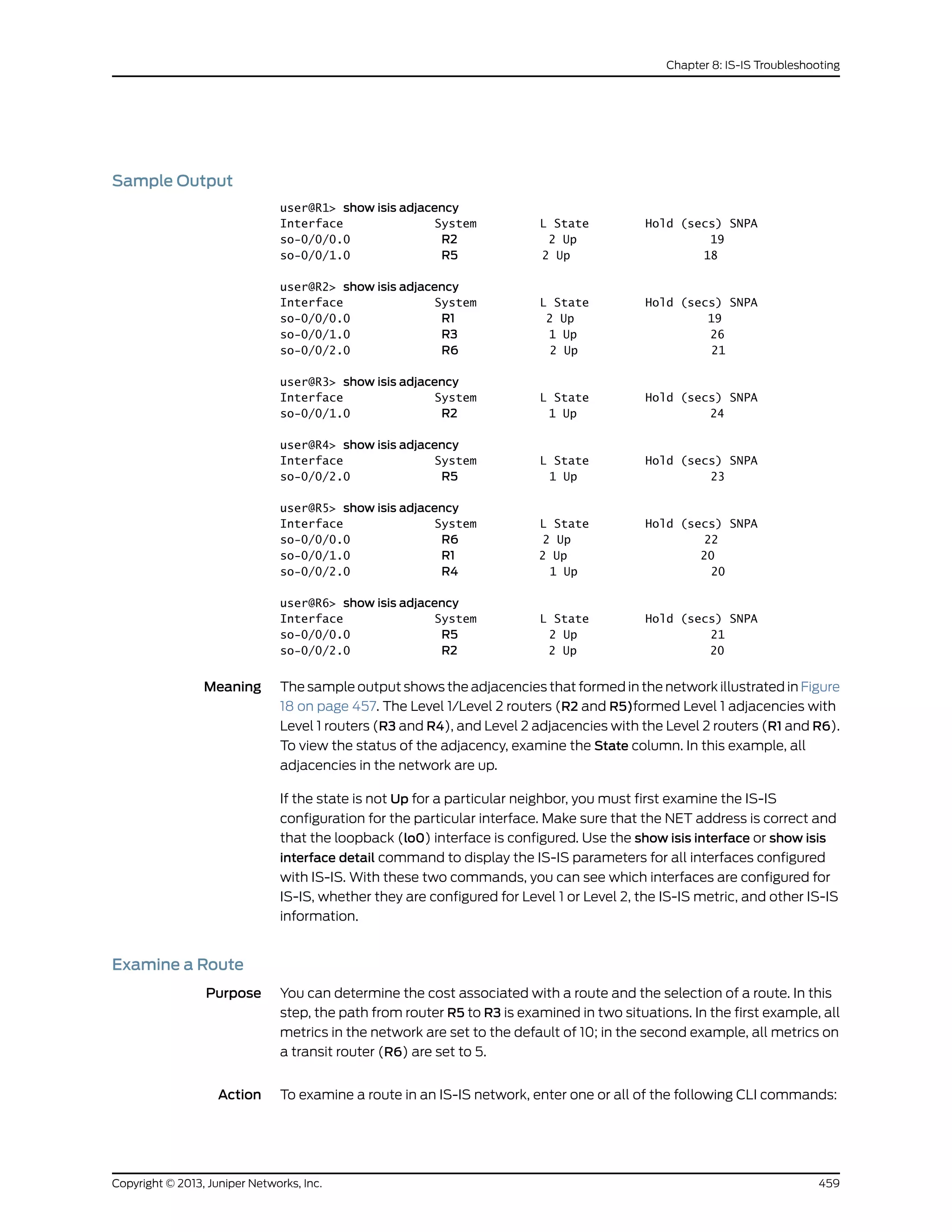
![user@host> show route destination-prefix
user@host> show route detail destination-prefix
user@host> show isis route destination-prefix
Sample Output 1 The following sample output shows the route from R5 to R3 when all metrics across
interfaces are set to the default of 10:
Sample Output
[edit protocols isis]
user@R6# show
level 1 disable;
interface so-0/0/0.0 {
level 2 metric 10;
}
interface so-0/0/2.0 {
level 2 metric 5;
}
interface fxp0.0 {
disable;
}
interface lo0.0;
Sample Output 2 The following sample output shows the route from R5 to R3 after the metric on R6 is
changed from the default of 10 to 5:
Sample Output
user@R5> show route 10.0.0.3
inet.0: 28 destinations, 28 routes (28 active, 0 holddown, 0 hidden)
+ = Active Route, - = Last Active, * = Both
10.0.0.3/32 *[IS-IS/18] 00:00:10, metric 25
> to 10.1.56.2 via so-0/0/0.0
user@R5> show route detail 10.0.0.3
inet.0: 28 destinations, 28 routes (28 active, 0 holddown, 0 hidden)
10.0.0.3/32 (1 entry, 1 announced)
*IS-IS Preference: 18
Level: 2
Next hop: 10.1.56.2 via so-0/0/0.0, selected
State: <Active Int>
Age: 4:57 Metric: 25
Task: IS-IS
Announcement bits (1): 0-KRT
AS path: I
user@R5> show isis route detail 10.0.0.3
IS-IS routing table Current version: L1: 250 L2: 257
Prefix L Version Metric Type Interface Via
10.0.0.3/32 2 257 25 int so-0/0/0.0 R6
Meaning Sample output 1 shows the cost for each route and the preferred next hop. In this example,
there are two next hops, one through R1 and the other through R6. Both have an equal
cost (30) to the destination. The cost is indicated in the Metric field. The preferred next
hop is randomly chosen. In this case, the preferred next hop is through R1, interface
so-0/0/1.0. In the output for the show route command, the selected next hop is indicated
by a forward arrow (>). With the show route detail command, the next hop is indicated
by the key word selected. The output for the show isis route command shows the selected
Copyright © 2013, Juniper Networks, Inc.460
IS-IS Configuration Guide](https://image.slidesharecdn.com/config-guide-routing-is-is-151104131021-lva1-app6891/75/Juniper-MX-Config-guide-routing-is-is-480-2048.jpg)
![interface and indicates that the IS-IS protocol is building the correct routing table from
the link-state database.
After the metric on R6 is changed to a lower value, sample output 2 shows a different
cost and next hop. With IS-IS, routes with lower total path metrics are preferred over
those with higher path metrics. The path through R6 (so-0/0/0.0) is now lower (25) than
the path through R1 (so-0/0/1.0) (30). In the output for the show route command, the
lower cost (25) is indicated in the Metric field, and the preferred path is indicated by the
forward arrow (>) and the keyword selected. The output for the show isis route command
shows the selected interface and indicates that the IS-IS protocol is building the correct
routing table from the link-state database.
In general, the output for the show route commands shows all active entries in the routing
table. The information displayed includes the name of the routing table (inet.0), the
number of destinations for which there are routes in the routing table (28), how the route
was learned, and the route preference value, such as [IS-IS/18]. In addition, any metric
associated with the route (metric 30), and the name of the interface through which the
route was learned are displayed.
Examine the Forwarding Table
Purpose You can display the set of routes installed in the forwarding table to verify that the routing
protocol process (rpd) has relayed the correct information into the forwarding table. This
is especially important when there are network problems, such as connectivity. In this
procedure, you verify that the routes displayed in Step 2 appear in the forwarding table
for router R5.
Action To examine the forwarding table for a router, enter the following CLI command:
user@host> show route forwarding-table destination destination-prefix
Sample Output
user@R5> show route forwarding-table destination 10.0.0.3
Routing table: inet
Internet:
Destination Type RtRef Next hop Type Index NhRef Netif
10.0.0.3/32 user 0 10.1.15.0 ucst 285 7 so-0/0/1.0
user@R5> show route forwarding-table destination 10.0.0.3
Routing table: inet
Internet:
Destination Type RtRef Next hop Type Index NhRef Netif
10.0.0.3/32 user 0 10.1.56.0 ucst 281 9 so-0/0/0.0
Meaning The sample output shows the selected next hop between routers R5 and R3 sent from
the inet routing table and installed into the forwarding table. The first instance shows
the route through R1 and the second instance shows the route through R6. In both
instances, the preferred route displayed in Step 2 is installed in the forwarding table.
In general, the sample output includes the destination address and destination type, the
next-hop address and next-hop type, the number of references to the next hop, an index
number into an internal next-hop database, and the interface used to reach the next hop.
461Copyright © 2013, Juniper Networks, Inc.
Chapter 8: IS-IS Troubleshooting](https://image.slidesharecdn.com/config-guide-routing-is-is-151104131021-lva1-app6891/75/Juniper-MX-Config-guide-routing-is-is-481-2048.jpg)
![Sample Output
user@R1> show isis database
IS-IS level 1 link-state database:
0 LSPs
IS-IS level 2 link-state database:
LSP ID Sequence Checksum Lifetime Attributes
R1.00-00 0x1b 0xd4b5 583 L1 L2
R2.00-00 0x1d 0x1a4f 1131 L1 L2
R5.00-00 0x1b 0x6245 883 L1 L2
R6.00-00 0x20 0xf7c 919 L1 L2
4 LSPs
user@R2> show isis database
IS-IS level 1 link-state database:
LSP ID Sequence Checksum Lifetime Attributes
R2.00-00 0x56 0xbd8c 862 L1 L2 Attached
R3.00-00 0x58 0xaca1 463 L1
2 LSPs
IS-IS level 2 link-state database:
LSP ID Sequence Checksum Lifetime Attributes
R1.00-00 0x57 0x3e10 871 L1 L2
R2.00-00 0x5e 0x9790 1150 L1 L2
R5.00-00 0x5a 0xadba 1162 L1 L2
R6.00-00 0x56 0xa2b2 484 L1 L2
4 LSPs
user@R3> show isis database
IS-IS level 1 link-state database:
LSP ID Sequence Checksum Lifetime Attributes
R2.00-00 0x56 0xbd8c 792 L1 L2 Attached
R3.00-00 0x58 0xaca1 397 L1
2 LSPs
IS-IS level 2 link-state database:
0 LSPs
[edit protocols isis]
user@R4> show isis database
IS-IS level 1 link-state database:
LSP ID Sequence Checksum Lifetime Attributes
R4.00-00 0x56 0x34b8 1125 L1
R5.00-00 0x57 0x22bb 795 L1 L2 Attached
2 LSPs
IS-IS level 2 link-state database:
0 LSPs
user@R5> show isis database
IS-IS level 1 link-state database:
LSP ID Sequence Checksum Lifetime Attributes
R4.00-00 0x56 0x34b8 1071 L1
R5.00-00 0x57 0x22bb 745 L1 L2 Attached
2 LSPs
IS-IS level 2 link-state database:
LSP ID Sequence Checksum Lifetime Attributes
R1.00-00 0x57 0x3e10 707 L1 L2
R2.00-00 0x5e 0x9790 982 L1 L2
R5.00-00 0x5a 0xadba 1002 L1 L2
R6.00-00 0x57 0xa0b3 1064 L1 L2
4 LSPs
463Copyright © 2013, Juniper Networks, Inc.
Chapter 8: IS-IS Troubleshooting](https://image.slidesharecdn.com/config-guide-routing-is-is-151104131021-lva1-app6891/75/Juniper-MX-Config-guide-routing-is-is-483-2048.jpg)
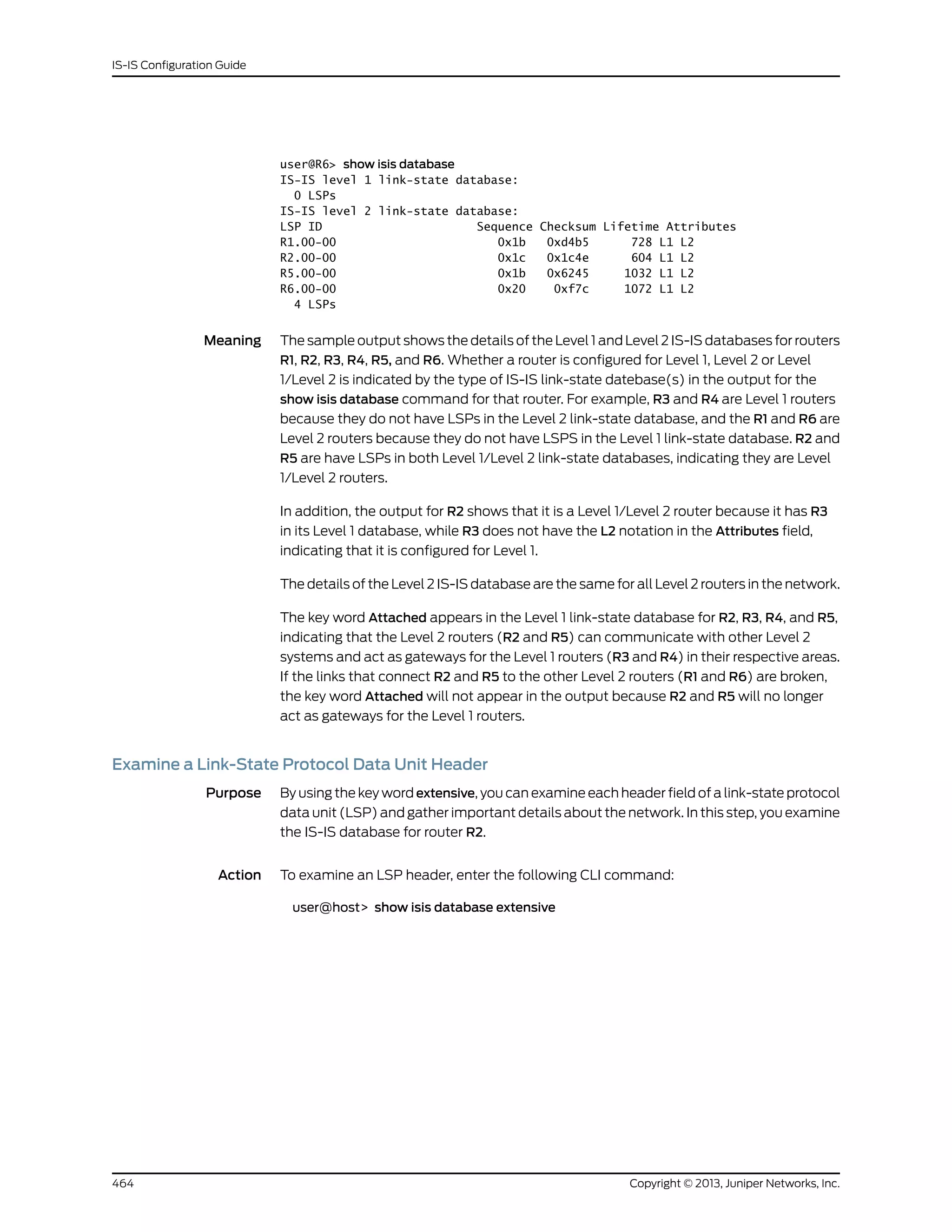
![Sample Output
user@R2> show isis database extensive
IS-IS level 1 link-state database:
[...Output truncated...]
Header: LSP ID: R2.00-00 , Length: 139 bytes
Allocated length: 1492 bytes, Router ID: 10.0.0.2
Remaining lifetime: 1071 secs, Level: 1 ,Interface: 0
Estimated free bytes: 1353, Actual free bytes: 1353
Aging timer expires in: 1071 secs
Protocols: IP, IPv6
Packet: LSP ID: R2.00-00, Length: 139 bytes, Lifetime : 1198 secs
Checksum: 0xbb8d, Sequence: 0x57, Attributes: 0xb <L1 L2 Attached>
NLPID: 0x83, Fixed length: 27 bytes, Version: 1, Sysid length: 0 bytes
Packet type: 18 , Packet version: 1, Max area: 0
[...Output truncated...]
Header: LSP ID: R3.00-00 , Length: 139 bytes
Allocated length: 284 bytes, Router ID: 10.0.0.3
Remaining lifetime: 823 secs, Level: 1 ,Interface: 68
Estimated free bytes: 145, Actual free bytes: 145
Aging timer expires in: 823 secs
Protocols: IP, IPv6
Packet: LSP ID: R3.00-00, Length: 139 bytes, Lifetime : 1198 secs
Checksum: 0xaaa2, Sequence: 0x59, Attributes: 0x1 <L1>
NLPID: 0x83, Fixed length: 27 bytes, Version: 1, Sysid length: 0 bytes
Packet type: 18, Packet version: 1, Max area: 0
[...Output truncated...]
IS-IS level 2 link-state database:
[...Output truncated...]
Header: LSP ID: R1.00-00, Length: 194 bytes
Allocated length: 284 bytes, Router ID: 10.0.0.1
Remaining lifetime: 398 secs, Level: 2 ,Interface: 67
Estimated free bytes: 145, Actual free bytes: 90
Aging timer expires in: 398 secs
Protocols: IP, IPv6
Packet: LSP ID: R1.00-00, Length: 194 bytes, Lifetime : 1196 secs
Checksum: 0x3e10, Sequence: 0x57, Attributes: 0x3 <L1 L2>
NLPID: 0x83, Fixed length: 27 bytes, Version: 1, Sysid length: 0 bytes
Packet type: 20 , Packet version: 1, Max area: 0
[...Output truncated...]
Header: LSP ID: R2.00-00 , Length: 236 bytes
Allocated length: 1492 bytes, Router ID: 10.0.0.2
Remaining lifetime: 677 secs, Level: 2 ,Interface: 0
Estimated free bytes: 1256, Actual free bytes: 1256
Aging timer expires in: 677 secs
Protocols: IP, IPv6
Packet: LSP ID: R2.00-00, Length: 236 bytes, Lifetime : 1198 secs
Checksum: 0x9790, Sequence: 0x5e, Attributes: 0x3 <L1 L2>
NLPID: 0x83, Fixed length: 27 bytes, Version: 1, Sysid length: 0 bytes
Packet type: 20, Packet version: 1, Max area: 0
[...Output truncated...]
Meaning The sample output is from router R2 and shows extensive information about the Level 1
and Level 2 link-state databases, which are identical across all Level 2 routers. Level 1
routers only include information for the Level 1 link-state database, which is identical to
the Level 1 information in the output for a Level 2 router. The sample output shows the
details of four LSPs. Level 1 and Level 2 LSPs include identical types of information except
465Copyright © 2013, Juniper Networks, Inc.
Chapter 8: IS-IS Troubleshooting](https://image.slidesharecdn.com/config-guide-routing-is-is-151104131021-lva1-app6891/75/Juniper-MX-Config-guide-routing-is-is-485-2048.jpg)
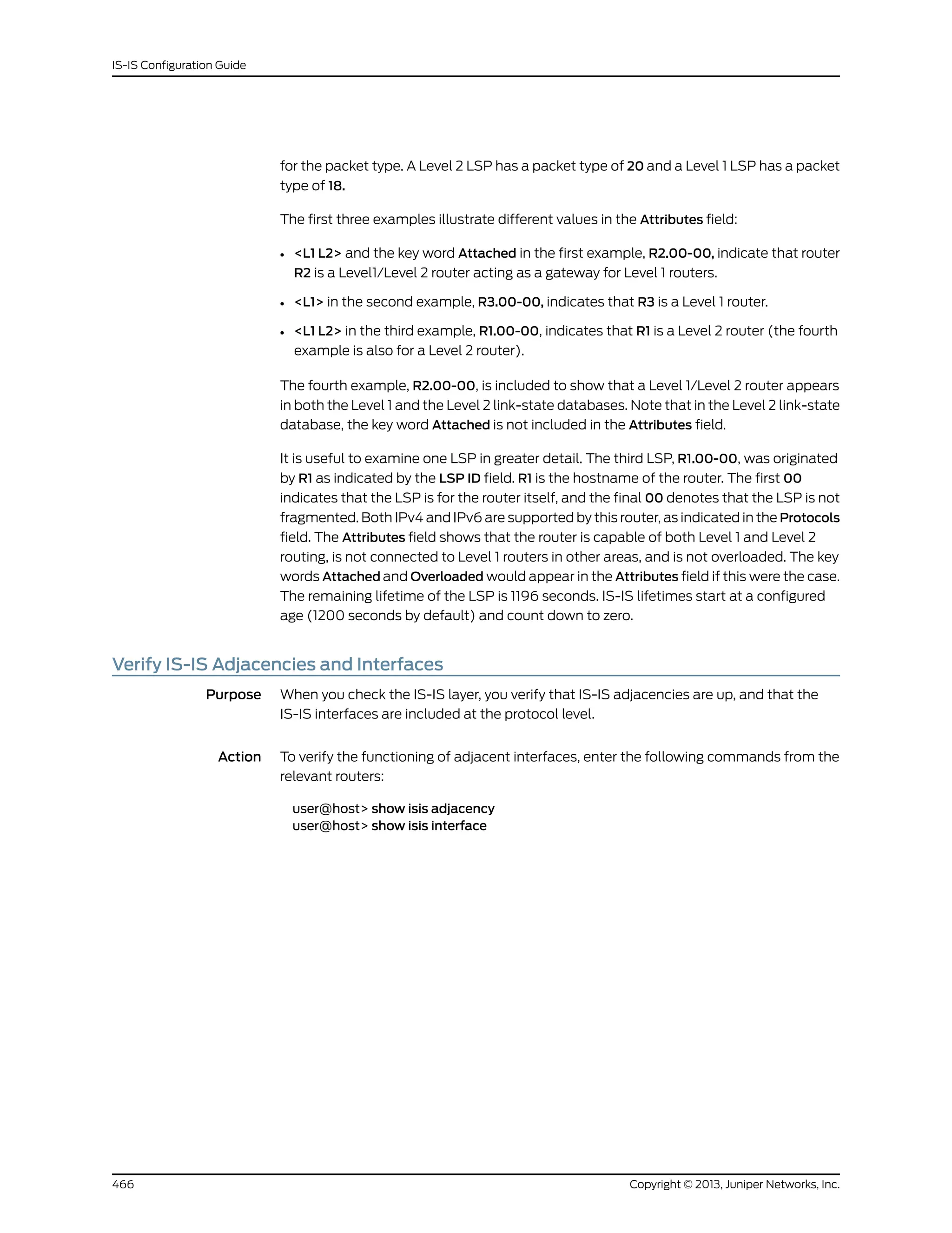
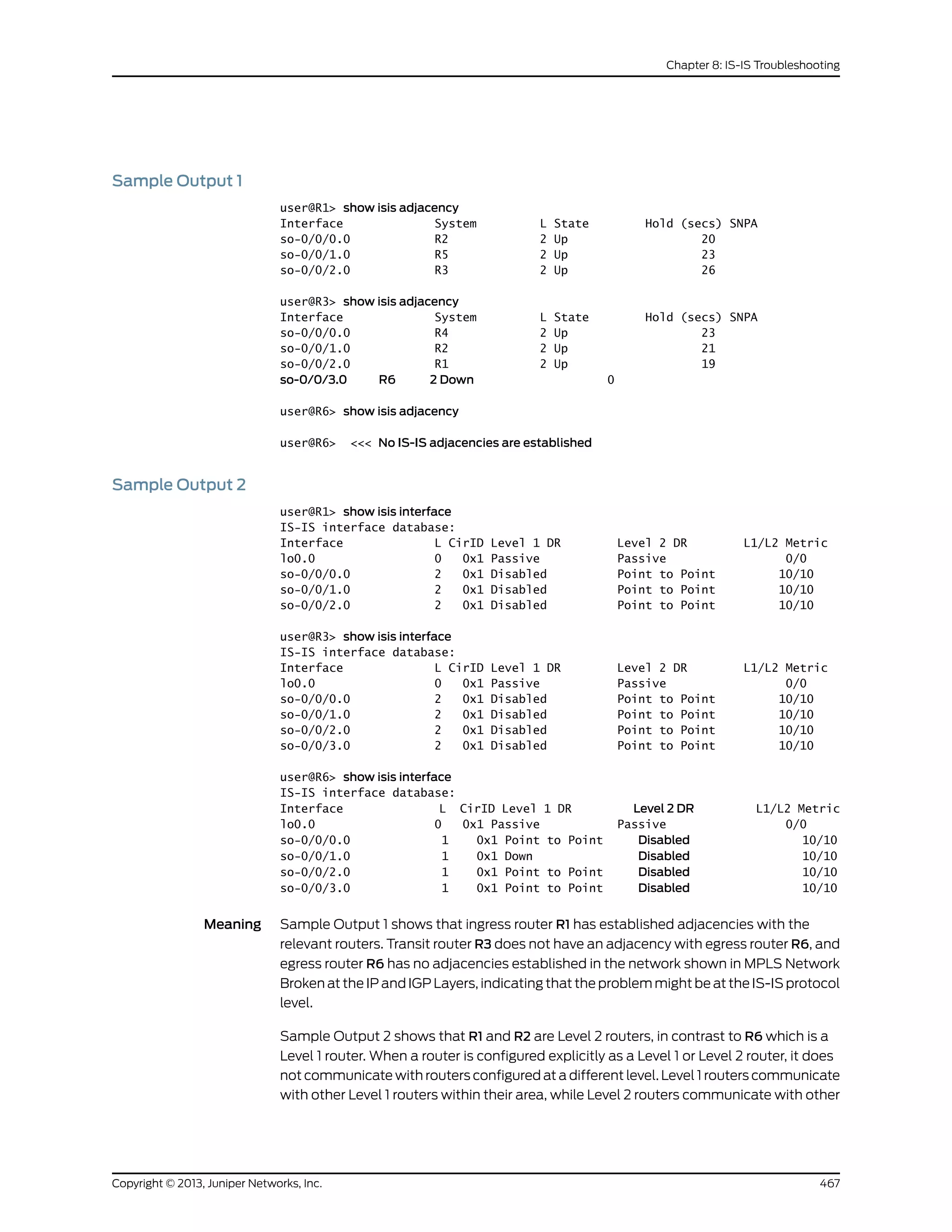
![Level 2 routers, and towards other autonomous systems. Because all the routers in this
network are configured for Level 2, they cannot form an adjacency with R6, which is
incorrectly configured as a Level 1 router.
Display Detailed IS-IS Protocol Information
Action To trace IS-IS messages in detail, follow these steps:
1. In configuration mode, go to the following hierarchy level:
[edit]
user@host# edit protocols isis traceoptions
2. Configure the flag to display detailed IS-IS protocol messages:
[edit protocols isis traceoptions]
user@host# set flag hello detail
3. Verify the configuration:
user@host# show
For example:
[edit protocols isis traceoptions]
user@host# show
file isislog size 10k files 10;
flag hello detail;
4. Commit the configuration:
user@host# commit
5. View the contents of the file containing the detailed messages:
user@host# run show log filename
For example:
user@host# run show log isislog
Nov 29 23:17:50 trace_on: Tracing to "/var/log/isislog" started
Nov 29 23:17:50 Sending PTP IIH on so-1/1/1.0
Nov 29 23:17:53 Sending PTP IIH on so-1/1/0.0
Nov 29 23:17:54 Received PTP IIH, source id abc-core-01 on so-1/1/0.0
Nov 29 23:17:54 from interface index 11
Nov 29 23:17:54 max area 0, circuit type l2, packet length 4469
Nov 29 23:17:54 hold time 30, circuit id 6
Nov 29 23:17:54 neighbor state up
Nov 29 23:17:54 speaks IP
Nov 29 23:17:54 area address 99.0008 (1)
Nov 29 23:17:54 IP address 10.10.10.29
Nov 29 23:17:54 4396 bytes of total padding
Nov 29 23:17:54 updating neighbor abc-core-01
Nov 29 23:17:55 Received PTP IIH, source id abc-core-02 on so-1/1/1.0
Nov 29 23:17:55 from interface index 12
Nov 29 23:17:55 max area 0, circuit type l2, packet length 4469
Nov 29 23:17:55 hold time 30, circuit id 6
Nov 29 23:17:55 neighbor state up
Nov 29 23:17:55 speaks IP
Nov 29 23:17:55 area address 99.0000 (1)
Nov 29 23:17:55 IP address 10.10.10.33
Copyright © 2013, Juniper Networks, Inc.468
IS-IS Configuration Guide](https://image.slidesharecdn.com/config-guide-routing-is-is-151104131021-lva1-app6891/75/Juniper-MX-Config-guide-routing-is-is-488-2048.jpg)
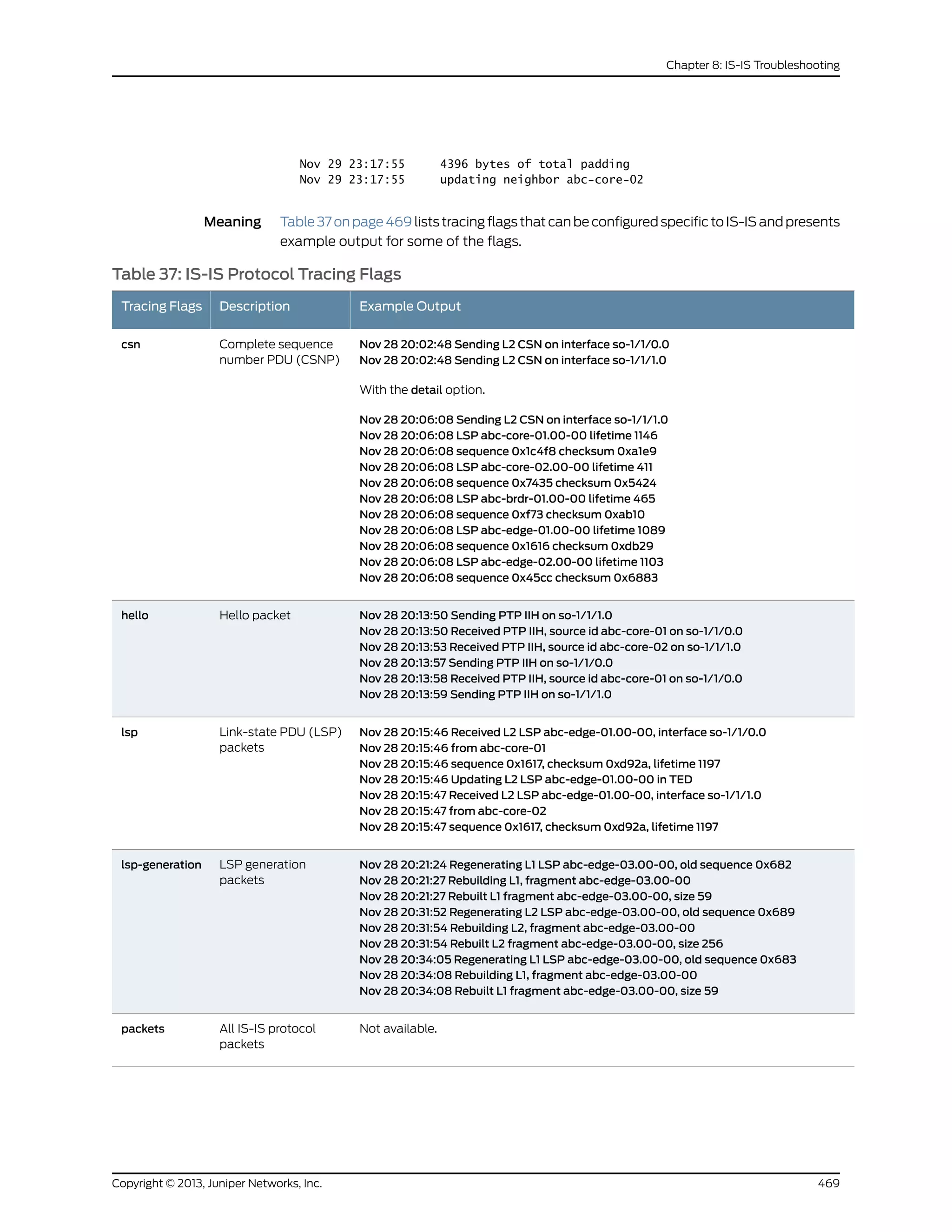
![Table 37: IS-IS Protocol Tracing Flags (continued)
Example OutputDescriptionTracing Flags
Nov 28 20:40:39 Received L2 PSN, source abc-core-01, interface so-1/1/0.0
Nov 28 20:40:39 Received L2 PSN, source abc-core-02, interface so-1/1/1.0
Nov 28 20:41:36 Sending L2 PSN on interface so-1/1/1.0
Nov 28 20:41:36 Sending L2 PSN on interface so-1/1/0.0
Nov 28 20:42:35 Received L2 PSN, source abc-core-02, interface so-1/1/1.0
Nov 28 20:42:35 LSP abc-edge-03.00-00 lifetime 1196
Nov 28 20:42:35 sequence 0x68c checksum 0x746d
Nov 28 20:42:35 Received L2 PSN, source abc-core-01, interface so-1/1/0.0
Nov 28 20:42:35 LSP abc-edge-03.00-00 lifetime 1196
Nov 28 20:42:35 sequence 0x68c checksum 0x746d
Nov 28 20:42:49 Sending L2 PSN on interface so-1/1/1.0
Nov 28 20:42:49 LSP abc-core-01.00-00 lifetime 1197
Nov 28 20:42:49 sequence 0x1c4fb checksum 0x9bec
Nov 28 20:42:49 Sending L2 PSN on interface so-1/1/0.0Nov 28 20:42:49 LSP
abc-core-01.00-00 lifetime 1197
Nov 28 20:42:49 sequence 0x1c4fb checksum 0x9bec
Partial sequence
number PDU (PSNP)
packets
psn
Nov 28 20:44:01 Scheduling SPF for L1: Reconfig
Nov 28 20:44:01 Scheduling multicast SPF for L1: Reconfig
Nov 28 20:44:01 Scheduling SPF for L2: Reconfig
Nov 28 20:44:01 Scheduling multicast SPF for L2: Reconfig
Nov 28 20:44:02 Running L1 SPF
Nov 28 20:44:02 L1 SPF initialization complete: 0.000099s cumulative time
Nov 28 20:44:02 L1 SPF primary processing complete: 0.000303s cumulative time
Nov 28 20:44:02 L1 SPF result postprocessing complete: 0.000497s cumulative time
Nov 28 20:44:02 L1 SPF RIB postprocessing complete: 0.000626s cumulative time
Nov 28 20:44:02 L1 SPF routing table postprocessing complete: 0.000736s cumulative
time
Shortest path first
(SPF) calculations
spf
Analyze IS-IS-Link State Packets in Detail
Action To analyze IS-IS link-state packets (LSPs) in detail, follow these steps:
1. In configuration mode, go to the following hierarchy level:
[edit]
user@host# edit protocols isis traceoptions
2. Configure IS-IS open messages:
[edit protocols isis traceoptions]
user@host# set flag lsp detail
3. Verify the configuration:
user@host# show
For example:
[edit protocols isis traceoptions]
user@host# show
file isislog size 5m world-readable;
flag error;
flag lsp detail;
Copyright © 2013, Juniper Networks, Inc.470
IS-IS Configuration Guide](https://image.slidesharecdn.com/config-guide-routing-is-is-151104131021-lva1-app6891/75/Juniper-MX-Config-guide-routing-is-is-490-2048.jpg)
![4. Commit the configuration:
user@host# commit
5. View the contents of the file containing the detailed messages:
user@host# run show log filename
For example:
user@host# run show log isislog
Nov 28 20:17:24 Received L2 LSP abc-core-01.00-00, interface so-1/1/0.0
Nov 28 20:17:24 from abc-core-01
Nov 28 20:17:24 sequence 0x1c4f9, checksum 0x9fea, lifetime 1199
Nov 28 20:17:24 max area 0, length 426
Nov 28 20:17:24 no partition repair, no database overload
Nov 28 20:17:24 IS type 3, metric type 0
Nov 28 20:17:24 area address 99.0908 (1)
Nov 28 20:17:24 speaks CLNP
Nov 28 20:17:24 speaks IP
Nov 28 20:17:24 dyn hostname abc-core-01
Nov 28 20:17:24 IP address 10.10.134.11
Nov 28 20:17:24 IP prefix: 10.10.10.0/30 metric 1 up
Nov 28 20:17:24 IP prefix: 10.10.10.4/30 metric 5 up
Nov 28 20:17:24 IP prefix: 10.10.10.56/30 metric 5 up
Nov 28 20:17:24 IP prefix: 10.10.10.52/30 metric 1 up
Nov 28 20:17:24 IP prefix: 10.10.10.64/30 metric 5 up
Nov 28 20:17:24 IP prefix: 10.10.10.20/30 metric 5 up
Nov 28 20:17:24 IP prefix: 10.10.10.28/30 metric 5 up
Nov 28 20:17:24 IP prefix: 10.10.10.44/30 metric 5 up
Nov 28 20:17:24 IP prefix 10.10.10.0 255.255.255.252
Nov 28 20:17:24 internal, metrics: default 1
Nov 28 20:17:24 IP prefix 10.10.10.4 255.255.255.252
Nov 28 20:17:24 internal, metrics: default 5
Nov 28 20:17:24 IP prefix 10.10.10.56 255.255.255.252
Nov 28 20:17:24 internal, metrics: default 5
Nov 28 20:17:24 IP prefix 10.10.10.52 255.255.255.252
Nov 28 20:17:24 internal, metrics: default 1
Nov 28 20:17:24 IP prefix 10.10.10.64 255.255.255.252
Nov 28 20:17:24 internal, metrics: default 5
Nov 28 20:17:24 IP prefix 10.10.10.20 255.255.255.252
Nov 28 20:17:24 internal, metrics: default 5
Nov 28 20:17:24 IP prefix 10.10.10.28 255.255.255.252
Nov 28 20:17:24 internal, metrics: default 5
Nov 28 20:17:24 IP prefix 10.10.10.44 255.255.255.252
Nov 28 20:17:24 internal, metrics: default 5
Nov 28 20:17:24 IS neighbors:
Nov 28 20:17:24 IS neighbor abc-core-02.00
Nov 28 20:17:24 internal, metrics: default 1
[...Output truncated...]
Nov 28 20:17:24 internal, metrics: default 5
Nov 28 20:17:24 IS neighbor abc-brdr-01.00
Nov 28 20:17:24 internal, metrics: default 5
Nov 28 20:17:24 IS neighbor abc-core-02.00, metric: 1
Nov 28 20:17:24 IS neighbor abc-esr-02.00, metric: 5
Nov 28 20:17:24 IS neighbor abc-edge-03.00, metric: 5
Nov 28 20:17:24 IS neighbor abc-edge-01.00, metric: 5
Nov 28 20:17:24 IS neighbor abc-edge-02.00, metric: 5
Nov 28 20:17:24 IS neighbor abc-brdr-01.00, metric: 5
Nov 28 20:17:24 IP prefix: 10.10.134.11/32 metric 0 up
Nov 28 20:17:24 IP prefix: 10.11.0.0/16 metric 5 up
Nov 28 20:17:24 IP prefix: 10.211.0.0/16 metric 0 up
471Copyright © 2013, Juniper Networks, Inc.
Chapter 8: IS-IS Troubleshooting](https://image.slidesharecdn.com/config-guide-routing-is-is-151104131021-lva1-app6891/75/Juniper-MX-Config-guide-routing-is-is-491-2048.jpg)
![Nov 28 20:17:24 IP prefix 10.10.134.11 255.255.255.255
Nov 28 20:17:24 internal, metrics: default 0
Nov 28 20:17:24 IP prefix 10.11.0.0 255.255.0.0
Nov 28 20:17:24 internal, metrics: default 5
Nov 28 20:17:24 IP prefix 10.211.0.0 255.255.0.0
Nov 28 20:17:24 internal, metrics: default 0
Nov 28 20:17:24 Updating LSP
Nov 28 20:17:24 Updating L2 LSP abc-core-01.00-00 in TED
Nov 28 20:17:24 Analyzing subtlv's for abc-core-02.00
Nov 28 20:17:24 Analysis complete
Nov 28 20:17:24 Analyzing subtlv's for abc-esr-02.00
Nov 28 20:17:24 Analysis complete
Nov 28 20:17:24 Analyzing subtlv's for abc-edge-03.00
Nov 28 20:17:24 Analysis complete
Nov 28 20:17:24 Analyzing subtlv's for abc-edge-01.00
Nov 28 20:17:24 Analysis complete
Nov 28 20:17:24 Analyzing subtlv's for abc-edge-02.00
Nov 28 20:17:24 Analysis complete
Nov 28 20:17:24 Analyzing subtlv's for abc-brdr-01.00
Nov 28 20:17:24 Analysis complete
Nov 28 20:17:24 Scheduling L2 LSP abc-core-01.00-00 sequence 0x1c4f9 on
interface so-1/1/1.0
Display Sent or Received IS-IS Protocol Packets
Action To configure the tracing for only sent or received IS-IS protocol packets, follow these
steps:
1. In configuration mode, go to the following hierarchy level:
[edit]
user@host# edit protocol isis traceoptions
2. Configure the flag to display sent, received, or both sent and received packets:
[edit protocols isis traceoptions]
user@host# set flag hello send
or
[edit protocols isis traceoptions]
user@host# set flag hello receive
or
[edit protocols isis traceoptions]
user@host# set flag hello
3. Verify the configuration:
user@host# show
For example:
[edit protocols isis traceoptions]
user@host# show
file isislog size 10k files 10;
flag hello send;
or
Copyright © 2013, Juniper Networks, Inc.472
IS-IS Configuration Guide](https://image.slidesharecdn.com/config-guide-routing-is-is-151104131021-lva1-app6891/75/Juniper-MX-Config-guide-routing-is-is-492-2048.jpg)
![[edit protocols isis traceoptions]
user@host# show
file isislog size 10k files 10;
flag hello receive;
or
[edit protocols isis traceoptions]
user@host# show
file isislog size 10k files 10;
flag hello send receive;
4. Commit the configuration:
user@host# commit
5. View the contents of the file containing the detailed messages:
user@host# run show log filename
For example:
user@host# run show log isislog
Sep 27 18:17:01 ISIS periodic xmit to 01:80:c2:00:00:15 (IFL 2)
Sep 27 18:17:01 ISIS periodic xmit to 01:80:c2:00:00:14 (IFL 2)
Sep 27 18:17:03 ISIS periodic xmit to 01:80:c2:00:00:15 (IFL 2)
Sep 27 18:17:04 ISIS periodic xmit to 01:80:c2:00:00:14 (IFL 2)
Sep 27 18:17:06 ISIS L2 hello from 0000.0000.0008 (IFL 2) absorbed
Sep 27 18:17:06 ISIS periodic xmit to 01:80:c2:00:00:15 (IFL 2)
Sep 27 18:17:06 ISIS L1 hello from 0000.0000.0008 (IFL 2) absorbed
473Copyright © 2013, Juniper Networks, Inc.
Chapter 8: IS-IS Troubleshooting](https://image.slidesharecdn.com/config-guide-routing-is-is-151104131021-lva1-app6891/75/Juniper-MX-Config-guide-routing-is-is-493-2048.jpg)

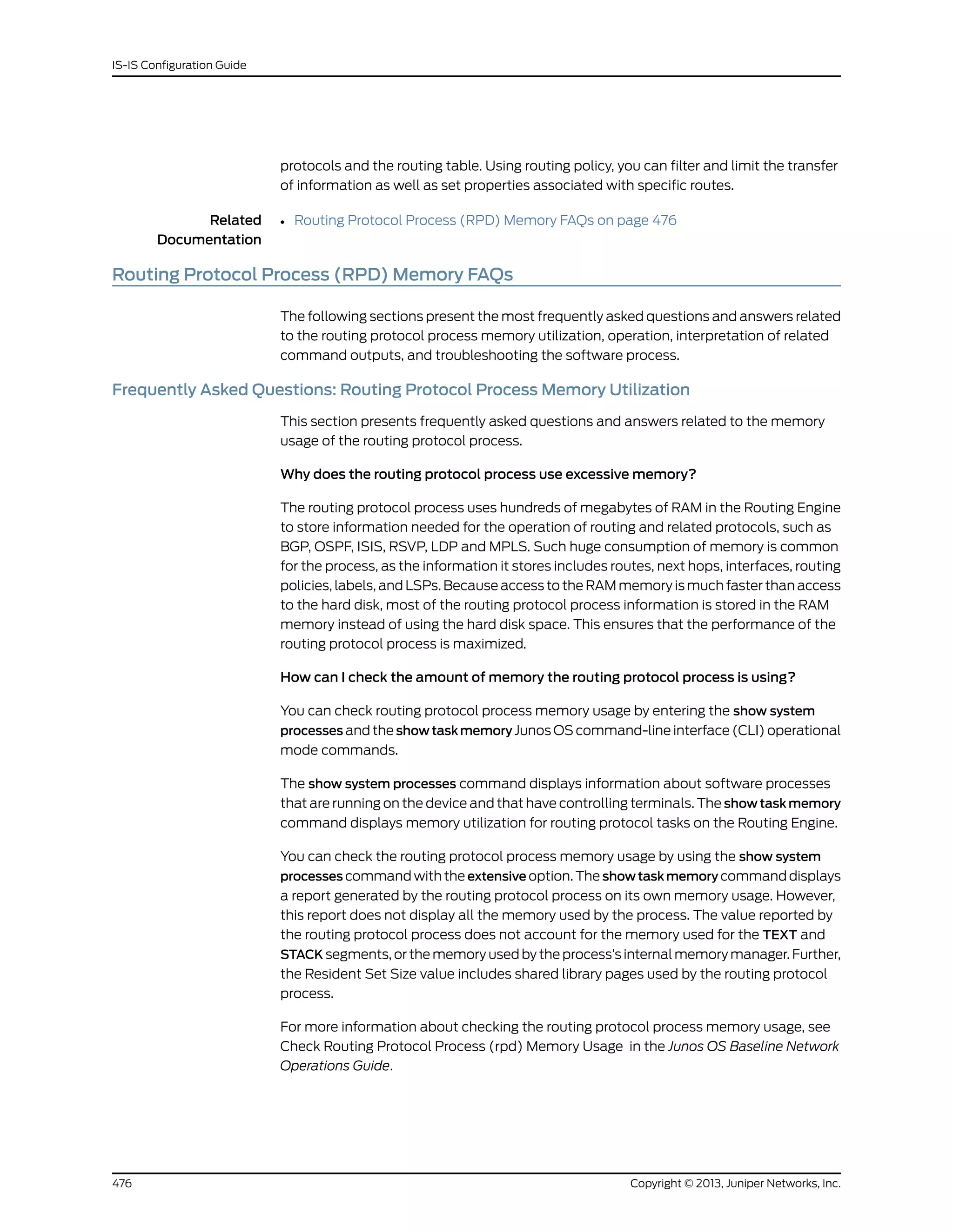
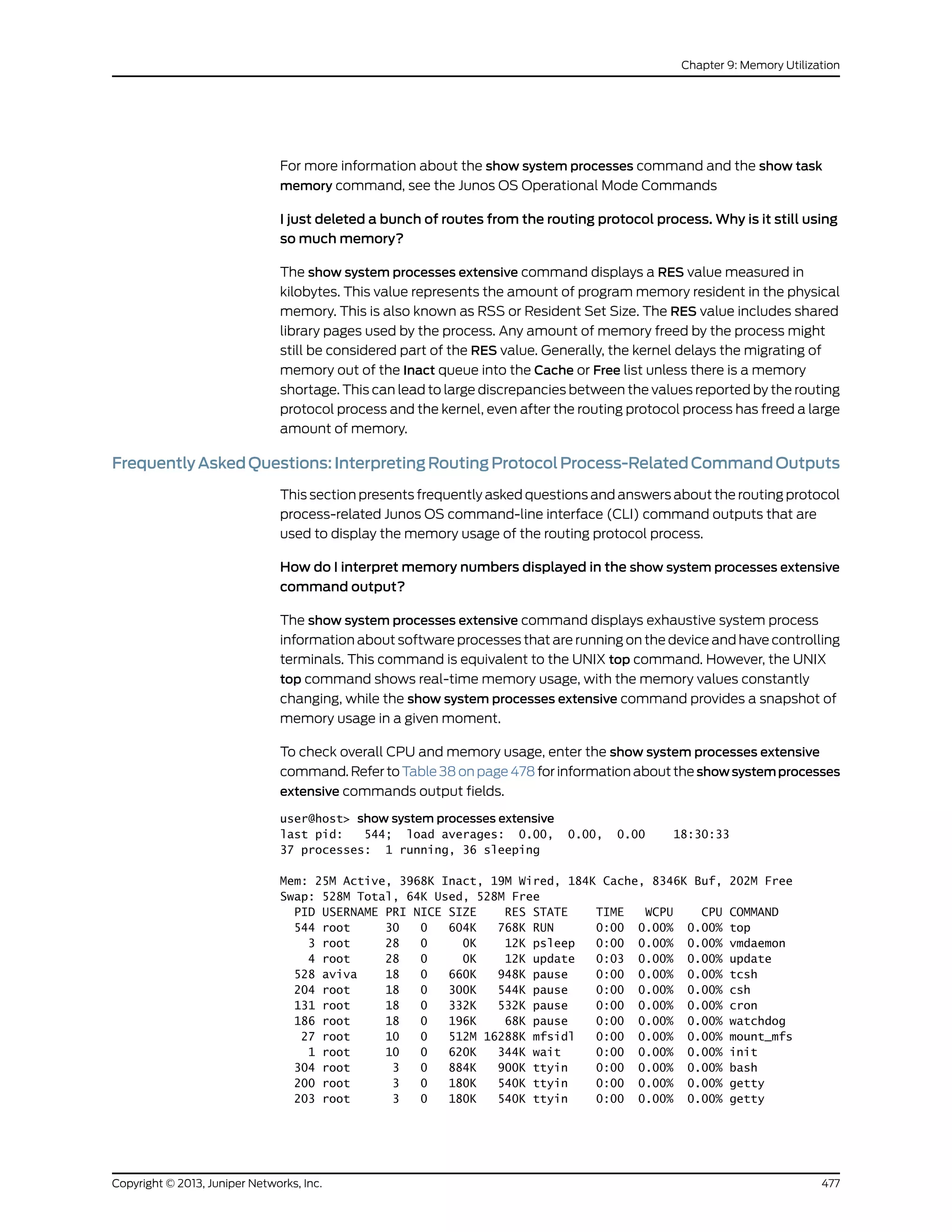
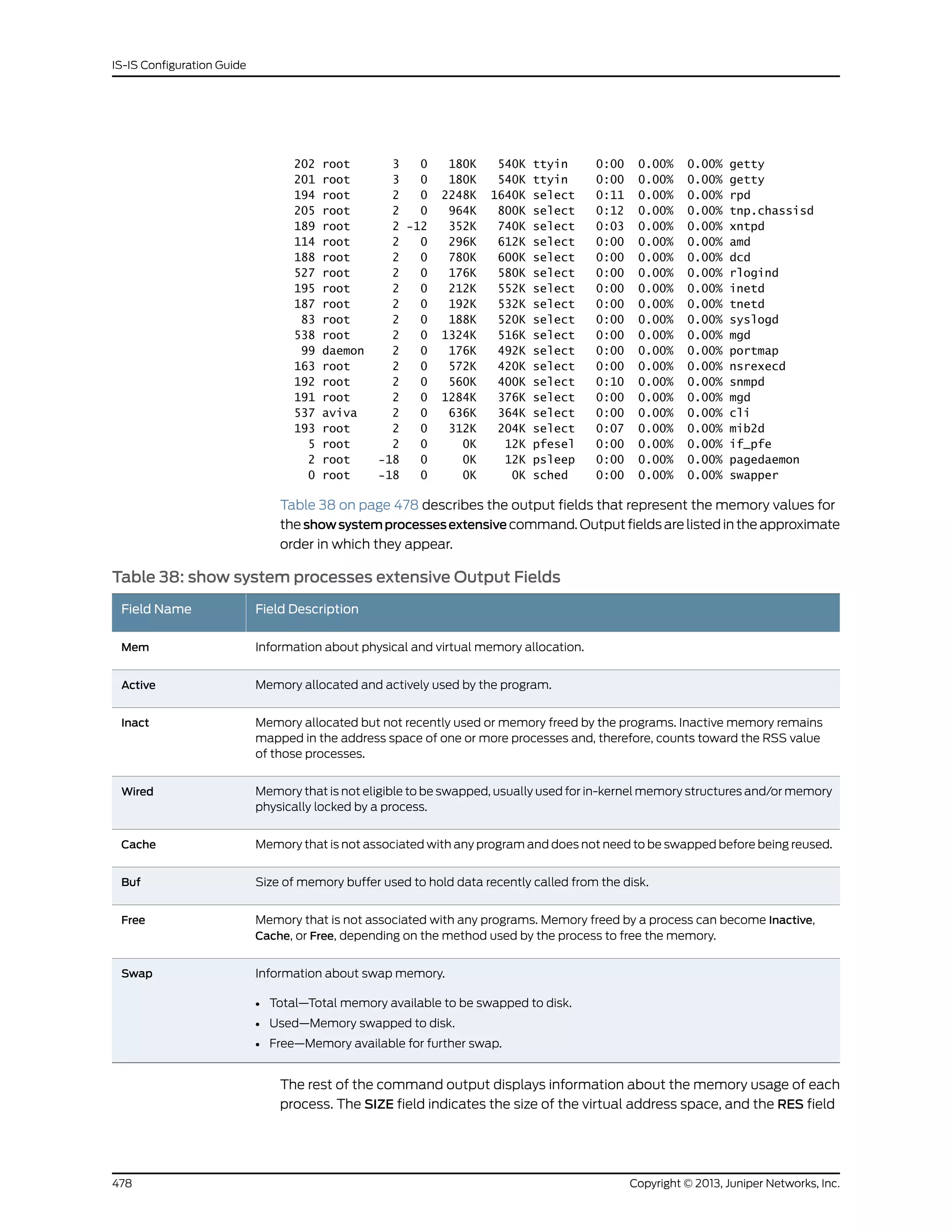
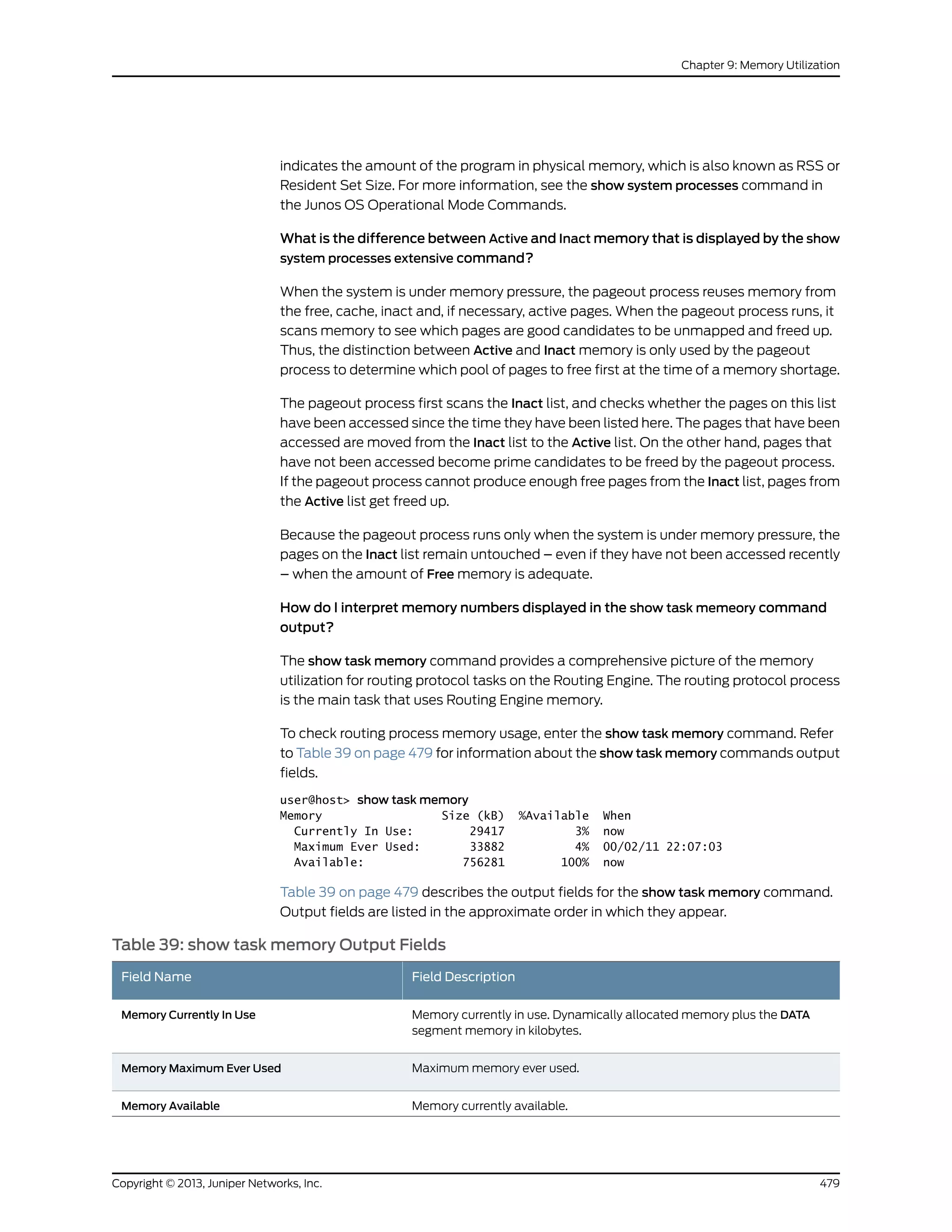
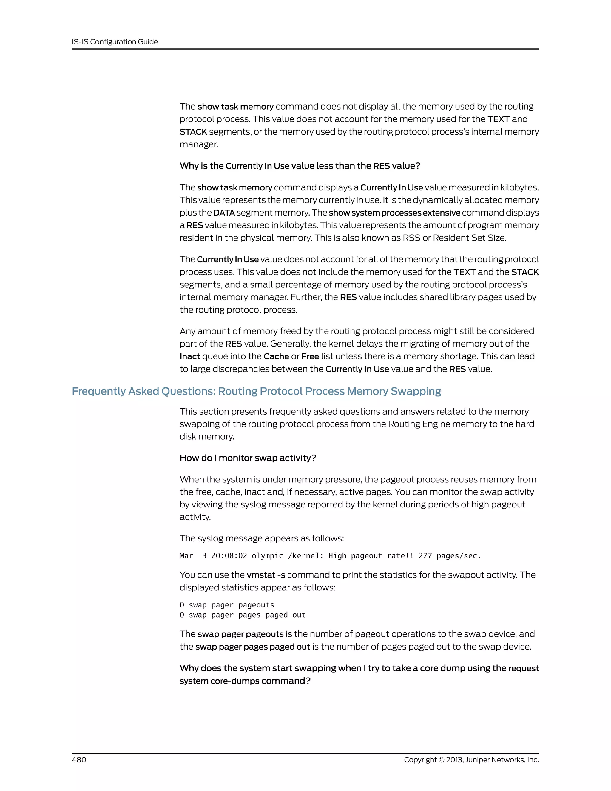


![Index
Symbols
#, comments in configuration statements.................xviii
( ), in syntax descriptions..................................................xviii
< >, in syntax descriptions.................................................xviii
[ ], in configuration statements.......................................xviii
{ }, in configuration statements......................................xviii
| (pipe), in syntax descriptions........................................xviii
A
access option
show route protocol command.............................398
access-internal option
show route protocol command.............................398
adjacencies
IS-IS
verifying .............................................441, 458, 466
IS-IS, verifying ..........................................441, 458, 466
advertisements, displaying ...............................................313
authentication
algorithm
IS-IS............................................................................45
IS-IS.....................................................................................45
keychains
IS-IS............................................................................45
authentication configuration
BFD......................................................................................69
authentication-algorithm statement
IS-IS
usage guidelines....................................................46
authentication-key statement
IS-IS...................................................................................152
usage guidelines............................................46, 118
authentication-key-chain statement............................153
IS-IS
usage guidelines....................................................46
authentication-type statement
IS-IS...................................................................................154
usage guidelines...................................................118
B
best routes, displaying.......................................................320
BFD
authentication configuration....................................69
protocol.............................................................................59
BFD authentication
for IS-IS...............................................................................72
bfd-liveness-detection statement
IS-IS...................................................................................155
usage guidelines....................................................59
BGP (Border Gateway Protocol)
export policy for CLNS..................................................111
braces, in configuration statements..............................xviii
brackets
angle, in syntax descriptions...................................xviii
square, in configuration statements.....................xviii
C
checklist for
IS-IS protocol, verifying.............................................437
checksum
for IS-IS.............................................................................114
checksum statement...........................................................157
clear isis adjacency command........................................236
clear isis database command.........................................238
clear isis overload command..........................................240
clear isis statistics command..........................................242
CLNS (Connectionless Network Service) VPNs
BGP export policy...........................................................111
IS-IS.....................................................................................111
clns-routing statement
IS-IS...................................................................................158
usage guidelines..................................................139
commands for
IS-IS protocol, verifying.............................................437
comments, in configuration statements.....................xviii
complete sequence number PDUs, IS-IS See IS-IS,
complete sequence number PDUs
conditions
routing policy.................................................................301
conventions
text and syntax..............................................................xvii
cost, IS-IS route selection................................................460
credibility-protocol-preference
traffic engineering
IS-IS.........................................................................228
csn (tracing flag)..................................................................225
csn, IS-IS protocol tracing flag.......................................469
csnp-interval statement.....................................................159
usage guidelines............................................................119
curly braces, in configuration statements...................xviii
485Copyright © 2013, Juniper Networks, Inc.](https://image.slidesharecdn.com/config-guide-routing-is-is-151104131021-lva1-app6891/75/Juniper-MX-Config-guide-routing-is-is-505-2048.jpg)


The document is a Juniper Networks IS-IS Configuration Guide that provides documentation on configuring the Intermediate System to Intermediate System (IS-IS) routing protocol. It includes sections on IS-IS overview and standards, configuration concepts and examples, and tasks for configuring IS-IS on Juniper routers and switches. The guide covers features such as multi-topology IS-IS, dual stacking of IPv4 and IPv6, authentication, BFD, and route protection. It provides configuration examples for common IS-IS scenarios.