SlideShare a Scribd company logo
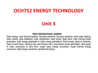
OCH752 ENERGY TECHNOLOGY
Unit 3
Conventional and Non-Conventional Energy
• Energy is one of the major parts of the economic
infrastructure, being the basic input needed to
sustain economic growth.
• The more developed is a country, the higher is the
per capita of energy consumption and vice-versa.
• Human civilization relies on different sources of
energy.
• Two major sources of energy are,
(i) Conventional and
(ii) Non-conventional Energy Sources
Classification of Energy Sources
Conventional Sources of Energy
• These sources of energy are also known
as non-renewable sources of energy.
• Available in limited quantity apart from hydro-
electric power.
• Conventional energy sources are classified
into commercial and non-commercial.
Commercial Energy Sources
Coal
• More than 148790 coal deposits in India
• Between 2005-2006, the annual production
went up to 343 million tons
• India is the fourth-largest coal-producing
country
• Deposits are mostly found in Bihar, Orissa,
Madhya Pradesh, and Bengal.
Commercial Energy Sources
Oil and Natural Gas
• Today oil is considered to be the liquid gold.
• One of the crucial sources of energy in India
and the world.
• Oil is mostly used in planes, automobiles,
trains and ships.
• Mainly found in Assam, Gujarat and Mumbai
Commercial Energy Sources
Electricity
• Common source of energy and used for domestic and commercial
purposes.
• The electricity is mainly utilized in electrical appliances like Fridge,
T.V, washing machine and air conditioning.
Major sources of power generation
• Nuclear Power
• Thermal Power
• Hydro-electric power
Non-commercial energy sources
• Energy sources that are freely available are
considered non-commercial energy sources.
• Examples of non-commercial energy sources
are, Straw, dried dung, firewood.
Non-Conventional Energy Sources
Solar Energy
• Energy that is produced by sunlight
• Photovoltaic cells are exposed to sunlight
• Energy is utilized for cooking and distillation of
water
Wind Energy
• Generated by harnessing the power of wind
• Mostly used in operating water pumps for irrigation
purposes
• India stands as the second-largest country in the
generation of wind power
Non-Conventional Energy Sources
Tidal Energy
• Generated by exploiting the tidal waves of the
sea is known as tidal energy
• Yet to be tapped due to the lack of cost-
effective technology.
Difference Between Conventional and
Non-Conventional Energy
Solar Energy
Solar Radiation
Direct Radiation
– Sun rays reach earth’s surface without diffusion
Diffused Radiation
– Sun rays scattered deflected by cloud, air molecules,
pollutants from industries, forest fires etc.
Reflected Radiation
– Sun rays reflected from a surface
Global Solar Radiation
– Sum of diffused and direct radiation
Solar Constant
Solar Constant
• The solar constant is the integrated radiant flux (AKA
flux) (power per unit perpendicular-to-the-beam area per unit
time) from the Sun at the mean Earth-Sun distance
• The Astronomical Unit (AU) = 1.49597870700 x 10¹¹ m) from
the Sun.
• The solar constant is NOT exactly constant due to variations in
the solar luminosity
• The fiducial value of Solar Constant is calculated
Solar Constant = L/(4π r2)
= (3.828 x 1026)/(4π(1.49597870700 x 1011) 2]
= 1361.2 W/m2
Solar Radiation on Tilted Surface
Azimuth Angle
Solar Collector
• Collects heat by absorbing sunlight
• A special kind of heat exchangers that transform solar
radiation energy to internal energy of the transport medium
• It absorbs the incoming solar radiation, converts it into heat,
and transfers this heat to a fluid (usually air, water, or oil)
flowing through the collector
• The solar energy collected is carried from the circulating fluid
either directly to the hot water or space conditioning
equipment, or to a thermal energy storage tank
• From the storage tank it is used during night or cloudy days.
Solar Collector
• Major classification of solar collector is concentrating and
non-concentrating collector.
• Aperture area is same as absorber area in non-concentrating
collector.
• Non-concentrating collectors are typically used in residential
and commercial building
• Bigger aperture than absorber area in concentrating collector
• Concentrating collectors generate electricity by heating a
heat-transfer fluid to drive a turbine.
Classification of Solar Collectors
SAF – Synthetic Aromatic Fluid CPC – Compound Parabolic Collector
DSG – Direct Steam Generator HTF – Heat Transfer Fluid
Applications of Solar Collector
• To produce hot water for residential area
• To provide warm air
• To produce even superheated materials for electricity
generation
• Major categories of solar collectors are,
- Flat Plate Collector
- Evacuated Tube Collector
- Solar Concentrator
- Solar Tower
Flat Plate Solar Collector
• Flat-plate collectors, developed by Hottel and
Whillier in the 1950.
• The most common type of solar collector which are
widely used for domestic household hot-water
heating and space heating.
• Basically a black surface that is placed at a
convenient path of a sun.
Flat Plate Collector - Construction
• The most common solar thermal technology
• It consists of,
* A dark colored absorber plate with fluid
circulation passageways
* A transparent cover to allow transmission
of solar energy into the enclosure
• The sides and back of the enclosure are typically insulated to reduce
heat loss to the ambient
• A heat transfer fluid is circulated through the absorber's fluid
passageways to remove heat from the solar collector
• The circulation fluid in tropical and sub-tropical climates is typically
water
• In climates where freezing is likely, a heat transfer fluid similar to an
automotive antifreeze solution
Components of Flat Plate Collector
• A dark flat-plate absorber
• A transparent cover that reduces heat losses,
called GLAZING
• A heat-transport fluid (air, antifreeze or water)
to remove heat from the absorber
• A heat insulating backing
• Flow passage
• Enclosure
Solar Flat Plate Collector
Flat Plate Collector – Water Heating
EVACUATED TUBE SOLAR THERMAL COLLECTOR
• ETC’s are built to reduce convective and heat conduction loss
• Vacuum acts as a heat insulator
• Each evacuated tube consists of two glass tubes
• The outer tube is made of extremely strong transparent glass
that is able to withstand changing climatic conditions
• The inner tube is also made of glass, but coated with a special
selective coating which features excellent solar heat
absorption and minimal heat reflection properties
• The air is evacuated from the space between the two glass
tubes to form a vacuum
EVACUATED TUBE SOLAR THERMAL COLLECTOR
ETC – Working Principle
• Evacuated Tube
- Absorbs solar energy and converts it to usable heat
- A vacuum between the two glass layers insulates
against heat loss
- The Heat Transfer Fin helps to transfer heat to the
Heat Pipe
- The silicon rubber caps at the end of the tube
protect the tube and are UV resistant
ETC – Working Principle
• Heat Pipe
- Copper vacuum pipe that transfers the heat from
within the evacuated tube up to the manifold.
• Manifold
- Insulated box contains the copper header pipe
- The header is a pair of contoured copper pipes
with dry connect sockets that the heat pipes plug
into.
Classification of ETC
Direct Flow ETC
• Has two pipes that run down and back,
inside the tube.
• One pipe is for inlet fluid and the other for
outlet fluid.
• Since the fluid flows into and out of each
tube, the tubes are not easily replaced.
• If damage occurs in tube, it's possible that
all of the fluid could be pumped out of the
system - if a closed loop is used.
• Water will flow out as in a broken pipe, if
an open loop is used
Integrated Tank Solar Collectors
• Where temperatures are not likely to drop into the freezing zone,
many evacuated tube solar collectors are made with an integrated
storage tank at the top of the collector.
• It has many advantages over a system that uses a separate
standalone heat-exchanger tank.
• With the tank separate, it is necessary to operate solar controllers,
water pumps, expansion tanks, etc.
• These extra equipment can greatly increase the cost of the system.
• Separate heat exchanger tank can also be the single most expensive
component in your system
• Water flow is controlled via your standard household water
pressure.
• Reduction in electronics not only reduces the cost but also reduces
failure points and operational complexity
Integrated Tank Solar Collectors
Types of Concentrating Collectors
• Parabolic trough system
• Parabolic dish
• Power tower
• Stationary concentrating collectors
Parabolic Trough
Parabolic Trough
Parabolic Trough
• Shaped like the English letter “u”
• Concentrate sunlight onto a receiver tube that
is positioned along the focal line of the trough
Parabolic Trough
Concentrating Parabolic Dish
• Uses parabolic dish shaped mirrors to focus the sunlight at the
center of the parabolic dish where the receiver is mounted.
• The receiver is mounted at the focal point of the dish.
• The working liquid in the receiver is heated to very
high temperatures of about 200 O C to 750 O C
• This fluid is then used to generate electricity.
• Movable base can move the parabolic dish with the movement
of sun
• The parabolic dish keeps itself in best direction to get
maximum amount of sun light.
• The collected heat is typically utilized directly by a heat engine
mounted on the receiver moving with the dish structure
Solar Tower Collector
• Also known as 'central tower‘ power plant as well as heliostat
power plant
• A type of solar furnace using a tower to receive the focused
sunlight
• It uses an array of flat, movable mirrors (called heliostats)
• Early designs used these focused rays to heat water
• Used the resulting steam to power a turbine
• Newer designs using liquid sodium have been demonstrated,
and systems using molten salts (40% potassium nitrate,
60% sodium nitrate) as the working fluids.
Concentrating Solar Power (CSP)
Concentrating Solar Tower
• Power tower or central receiver systems utilize sun-tracking
mirrors called heliostats
• Heliostats focus sunlight onto a receiver at the top of a tower
• A heat transfer fluid heated in the receiver up to around
600ºC
• Steam is generated and used to drive a turbine to produce
electricity.
• Earliest power towers utilized steam as the heat transfer fluid,
which does not lend itself to storage
• But Gemasolar (2011), Crescent Dunes (2013), and Noor III
(2018) use molten salts because of their superior heat
transfer and energy storage capabilities
Solar Distiller Technology
Solar Distiller - Working Principle
• Solar radiation heats up the contaminated water
and allows the water to evaporate.
• The process of evaporation lifts only pure water
molecules up.
• Leaves the contaminant behind.
• The process of evaporation starts.
• Water vapour molecules hit the plastic or glass
ceiling through inside edge of solar still.
• The water vapour molecules cling to the surface
and reaches out to the container of clean water.
Solar Distiller
Solar Furnace
• It is based on the concentration of rays by reflecting
mirrors (9,600).
• The solar rays are picked up by a first set of steerable
mirrors located on the slope.
• They are sent to a second series of mirrors
(the concentrators), placed in a parabola.
• They are eventually converging on a circular target,
40 cm in diameter, on top of the central tower.
• Equivalent to concentrating the energy of "10,000
suns“.
• The solar furnace produces a peak power of 3200 kW.
Solar Furnace – Working Principle
Solar Furnace at Odeilo in France
Solar Pond
Solar Pond
Solar Pond
Solar Pond
• Solar pond is a pool of saltwater which collects and
stores solar thermal energy.
• The saltwater naturally forms a
vertical salinity gradient also known as a "halocline“.
• Low-salinity water floats on top of high-salinity water.
• The layers of salt solutions increase in concentration
(and therefore density) with depth.
• Below a certain depth, the solution has a uniformly
high salt concentration
Solar Pond
• When the sun's rays contact the bottom of a shallow
pool, they heat the water adjacent to the bottom.
• When water at the bottom of the pool is heated, it
becomes less dense than the cooler water above it.
• Convection begins.
• Solar ponds heat water by impeding this convection.
• Salt is added to the water until the lower layers of
water become completely saturated.
• High-salinity water at the bottom of the pond does
not mix readily with the low-salinity water above it.
Solar Pond
• When the bottom layer of water is heated, convection
occurs separately in the bottom and top layers.
• This greatly reduces heat loss, and allows for the high-
salinity water to get up to 90 °C while maintaining
30 °C low-salinity water
• Hot, salty water can then be pumped away for use in
electricity generation, through a turbine or as a source
of thermal energy
Advantages and Disadvantages
• Attractive for rural areas in developing countries.
• Very large area collectors can be set up for just the cost
of the clay or plastic pond liner.
• Accumulating salt crystals have to be removed and can
be a valuable by-product and a maintenance expense.
• No need for a separate collector.
• Extremely-large thermal mass means power is
generated night and day.
• Due to evaporation, non-saline water is constantly
required to maintain salinity gradients
Energy Plantation
• Burning the fossil fuels, cause environmental
issue.
• Environmental problems such as greenhouse
gas accumulation, acidification, air pollution,
water pollution, are caused,
• The largest emissions of carbon dioxide into
the air are due to coal combustion,
• Still, it continues to be used because it is
cheaper.
Energy Plantation
• Energy plantation is a process of producing energy.
• Currently, fossil fuels such as oil, coal and natural gas
represent the prime energy sources in the world.
• Approximately 80% of the total use of more than 400
EJ(exajoules) per year.
• It is anticipated that these sources of energy will be
depleted within the next 40–50 years.
• The expected environmental damages such as the
global warming and acid rain due to the production
of emissions from these sources have tempted the
world to try to reduce carbon emissions
Energy Plantation
• It can be reduced by shift towards utilizing a
variety of renewable energy resources (RES)
which are less environmentally harmful.
• World energy supplies have been dominated
by fossil fuels for decades.
• Today biomass contributes about 10–15% of
this demand.
• To prevent this renewable sources such as
wind, solar energy and Biomass must be used.
BIOMASS
• Agricultural or Natural waste is considered as
Biomass.
• Biomass means living matter.
• Examples are, Coconut shell, wood, sugarcane
trash, rice husk, corn waste, palm waste and
wooden chips.
Biomass
Carbon Cycle
Conversion of Biomass into Fuel
• Biomass can be directly burned as a fuel.
Types of Processes
• Direct Combustion
• Pyrolysis
• Gasification
• Chemical conversion
Solar Drying
• Solar dryers are devices that use solar energy
to dry the substances especially food.
Types of Solar Dryers
 Indirect
 Direct
Solar Dryer
Direct Solar Dryers
• Direct solar dryers expose the substance to be
dehydrated to direct sunlight.
• Historically, food and clothing was dried in the sun by
using lines, or laying the items on rocks or on top of
tents.
• In Mongolia cheese and meat are still traditionally
dried using the top of the tent as a solar dryer.
• These systems the solar drying is assisted by the
movement of the air (wind) that removes the more
saturated air away from the items being dried
Indirect Solar Dryer
Indirect Solar Dryers
• In indirect solar dryers, the black surface heats
incoming air rather than directly heating the
substance to be dried.
• This heated air is then passed over the substance to
be dried and exits upwards often through a chimney,
taking moisture released from the substance with it.
Solar Dryers
• https://www.youtube.com/watch?v=0H-6_9f-
3mE
Pyrolysis
• The word pyrolysis is coined from the Greek words "pyro"
which means fire and "lysis" which means separating
• Pyrolysis is a process of chemically decomposing organic
materials at elevated temperatures in the absence of oxygen.
• The process typically occurs at temperatures above 430 °C
(800 °F) and under pressure.
• It simultaneously involves the change of physical phase and
chemical composition and is an irreversible process.
• Pyrolysis is commonly used to convert organic materials into a
solid residue containing ash and carbon, small quantities of
liquid and gases.
Pyrolysis
• Extreme pyrolysis, on the other hand, yields carbon
as the residue and the process is called carbonization.
• Unlike other high-temperature processes like
hydrolysis and combustion, pyrolysis does not involve
reaction with water, oxygen or other reagents.
• It is practically not possible to achieve an oxygen- free
environment, a small amount of oxidation always
occurs in any pyrolysis system.
Advantages of Pyrolysis
• It is a simple, inexpensive technology for processing a wide
variety of feed-stocks.
• It reduces waste going to landfill and greenhouse gas
emissions.
• It reduces the risk of water pollution.
• It has the potential to reduce the country’s dependence on
imported energy resources by generating energy from
domestic resources.
• Waste management with the help of modern pyrolysis
technology is inexpensive than disposal to landfills.
• The construction of a pyrolysis power plant is a relatively
rapid process.
Applications of Pyrolysis
• It is widely used in the chemical industry to produce
methanol, activated carbon, charcoal and other substances
from wood.
• Synthetic gas produced from the conversion of waste using
pyrolysis can be used in gas or steam turbines for producing
electricity.
• A mixture of stone, soil, ceramics, and glass obtained from
pyrolytic waste can be used as a building material.
• It plays a major role in carbon-14 dating and mass
spectrometry.
• It is also used for several cooking procedures like caramelizing,
grilling, frying, and baking.
Types of Pyrolysis Reactions
• Slow Pyrolysis
• Flash Pyrolysis
• Fast Pyrolysis
• Microwave Pyrolysis
Wind Energy
• Wind is caused by the uneven heating of the atmosphere by
the sun.
• Variations in the earth's surface, and rotation of the earth
• Mountains, bodies of water, and vegetation all influence wind
flow patterns
• Wind turbines convert the energy in wind to electricity by
rotating propeller-like blades around a rotor.
• The rotor turns the drive shaft, which turns an electric
generator.
• Three key factors affect the amount of energy a turbine can
harness from the wind: wind speed, air density, and swept
area.
Equation for Wind Power
Where
P = power,
ρ = air density, kg/m3
A = swept area of blades given by A = π r2, m2
V = velocity of the wind, m/s
Wind speed
• The amount of energy in the wind varies with
the cube of the wind speed.
• In other words, if the wind speed doubles,
there is eight times more energy in the wind.
• Small changes in wind speed have a large
impact on the amount of power available in
the wind
Density of the air
• The more dense the air, the more energy received by
the turbine.
• Air density varies with elevation and temperature.
• Air is less dense at higher elevations than at sea
level.
• Warm air is less dense than cold air.
• Turbines will produce more power at lower
elevations and in locations with cooler average
temperatures
Swept area of the turbine
• The larger the swept area the more power the
turbine can capture from the wind.
• A small increase in blade length results in a
larger increase in the power available to the
turbine
Types of Wind Mills
• Horizontal-axis turbines
• Vertical-axis turbines
- Darrieus Wind Turbine
- Savonious Wind Turbine
Horizontal Axis Wind Turbine (HAWT)
HAWT and VAWT
HAWT and VAWT
Horizontal Axis Wind Turbine
• Horizontal-axis wind turbines (HAWT) have the main
rotor shaft and electrical generator at the top of a
tower.
• Must be pointed into the wind.
• Small turbines are pointed by a simple wind vane.
• Large turbines generally use a wind sensor coupled
with a servo motor
• Most have a gearbox, which turns the slow rotation
of the blades into a quicker rotation
• More suitable to drive an electrical generator
Horizontal Axis Wind Turbine
• The major disadvantage is increased fatigue due to
frequent oscillations caused by wind fluctuations.
• The downwind or wind downstream model are less
used than the upwind or wind upstream.
• The reduced number of blades theoretically reduces
the cost but leads to irregular torque.
Horizontal Axis Wind Turbine
• The largely dominant technology today is the three-bladed
HAWT.
• The turbine can be at the front of the nacelle (upwind) or at
the back (downwind).
• Downwind devices automatically face the wind direction and
therefore do not require mechanical orientation system.
• Therefore do not require mechanical orientation system
• The major disadvantage is increased fatigue due to frequent
oscillations caused by wind fluctuations.
• The downwind or wind downstream model are less used than
the upwind or wind upstream
Vertical Axis Wind Turbine (VAWT)
• Vertical-axis wind turbines (VAWTs) have an axis of rotation
that is vertical.
• Unlike the horizontal wind turbines, they can capture winds
from any direction without the need to reposition the rotor
when the wind direction changes.
• Vertical-axis wind turbines were also used in some applications
as they have the advantage that they do not depend on the
direction of the wind.
• It is possible to extract power relatively easier.
• Vertical axis wind turbines have been developed over recent
years with a number of large Darrieus type turbines (in US).
• VAWTs are typically small wind turbines that are characterized
by an axis of rotation that is perpendicular to the ground
Vertical Axis Wind Turbine
• VAWTs can operate independently of wind direction.
• It is a major advantage for urban applications where
wind direction can change rapidly.
• The lift-based Darrieus design looks like an eggbeater
and uses long airfoil shaped blades
• Darrieus turbines tend to have lower efficiencies
than HAWTs.
• But under the high-turbulence, directionally
fluctuating wind conditions of an urban setting,
Darrieus machines may run more smoothly and
produce more energy than HAWTs
Darrieus wind turbine
• The Darrieus wind turbine is a type
of vertical axis wind turbine (VAWT)
• Used to generate electricity from wind
energy.
• Turbine consists of a number of
curved aerofoil blades mounted on a
rotating shaft or framework.
• The curvature of the blades allows the blade
to be stressed only in tension at high
rotating speeds.
• This design of the turbine was patented
by Georges Jean Marie Darrieus,
a French aeronautical engineer, in 1926
Darrieus wind turbine
• In the original versions of the Darrieus design, the aerofoils
are arranged so that they are symmetrical and have
zero rigging angle.
• The angle that the aero-foils are set relative to the structure
on which they are mounted.
• When the Darrieus rotor is spinning, the aerofoils are moving
forward through the air in a circular path.
• Relative to the blade, this oncoming airflow is added
vectorially to the wind, so that the resultant airflow creates a
varying small positive angle of attack to the blade.
• This generates a net force pointing obliquely forwards along a
certain 'line-of-action'
Savonius wind turbine
• Savonius wind turbines are a type of vertical-axis wind
turbine (VAWT).
• Used for converting the force of the wind into torque on a
rotating shaft.
• The turbine consists of a number of aerofoils, usually—but not
always—vertically mounted on a rotating shaft or framework.
• Mounted either ground stationed or tethered in airborne
systems.
• Savonius wind turbine was invented by
the Finnish engineer Sigurd Johannes Savonius in 1922.
• Savonius turbine is one of the simplest
turbines. Aerodynamically, it is a drag-type device.
Wind Power in India
• Wind power generation capacity in India has significantly increased in
recent years.
• As of 30 September 2020, the total installed wind power capacity was
38.124 GW.
• The fourth largest installed wind power capacity in the world.
• Wind power costs in India are decreasing rapidly.
• Development of wind power in India began in December 1952.
• In September 1954, a Symposium on Solar Energy and Wind Power
organised by the CSIR and UNESCO was held in New Delhi.
• E. W. Golding, a British power engineer Convinced of the potential of wind
power in India, he recommended continued and extensive wind velocity
surveys in different regions of India.
• By this time, regions of Saurashtra and around Coimbatore had been
identified as promising sites for generating electricity from wind power
Wind Power in India
• In 1960, the CSIR established a Wind Power Division as part of
the new National Aeronautical Laboratory (NAL) in Bangalore.
• From the 1960s into the 1980s, the NAL and other groups
continued to carry out wind velocity surveys and develop
improved estimates of India's wind energy capacity.
• Large-scale development of wind power began in 1985 with the
first wind project in Veraval, Gujarat, in the form of a 40 kW.
• In 1986, demonstration wind farms were set up in the coastal
areas of Maharashtra (Ratnagiri), Gujarat (Okha) and Tamil
Nadu (Tirunelveli) with 55 kW Vestas wind turbines.
• These demonstration projects were supported by the Ministry of
New and Renewable Energy (MNRE).
Wind Power in India
• The potential for wind farms in the country was first assessed
in 2011 to be more than 2,000 GW by Prof. Jami Hossain of
TERI University, New Delhi.
• In 2015, the MNRE set the target for Wind Power generation
capacity by the year 2022 at 60,000 MW
OTEC - Layout
Ocean Thermal Energy Conversion
• Ocean Thermal Energy Conversion (OTEC) uses the ocean
thermal gradient between cooler deep and warmer shallow or
surface seawaters to run a heat engine.
• OTEC can operate with a very high capacity factor and so can
operate in base load mode.
• OTEC is one of the continuously available renewable energy
resources that could contribute to base-load power supply.
• The resource potential for OTEC is considered to be much
larger than for other ocean energy forms.
• Systems may be either closed-cycle or open-cycle.
• Closed-cycle OTEC uses working fluids that are typically
thought of as refrigerants such as ammonia or R-134a.
Ocean Thermal Energy Conversion
• These fluids have low boiling points, and are therefore
suitable for powering the system’s generator to generate
electricity.
• The most commonly used heat cycle for OTEC to date is
the Rankine cycle.
OCEAN THERMAL ENERGY CONVERSION
Tidal Energy Conversion
• Tidal energy is produced through the use of tidal
energy generators.
• These large underwater turbines are placed in areas
with high tidal movements.
• Designed to capture the kinetic motion of the ebbing
and surging of ocean tides in order to produce
electricity.
• Tidal power has great potential for future power and
electricity generation because of the massive size of
the oceans.
Geothermal Energy
• Geothermal energy ranges from shallow hot water to very
high temperatures of molten rock called magma.
• By utilizing heat pumps, systems can tap into this available
resource to cool and heat buildings.
• Magma is by far the most advantageous resource of
geothermal energy.
• It is currently limited because we have yet to develop the
technology to recover heat directly from the magma
• In United States, more geothermal reservoirs are found in the
western states like Hawaii and Alaska. Volcanic areas.
Advantages – Geothermal Energy
• Environmentally Friendly
• No fuel needed
• Smallest Land footprint as most piping is laid
underground
• Estimated saving of 30-60% on heating.
• 25-50% on cooling within just a few years.
Disadvantages – Geothermal Energy
• Suitable to particular regions – Zone specific.
• High initial costs
• Uses a ton of water
• Sulfur dioxide and silica discharges are
released into the air due to the process
• The site location must be able to withstand
temperatures of 350 degrees Fahrenheit for
the geothermal process
Thank you
Dr A R Pradeep Kumar, B.E., M.E., Ph.D.
Prof. /Mech.,
Dhanalakshmi College of Engineering,
Chennai
Email : dearpradeepkumar@gmail.com
99 41 42 43 37

More Related Content

What's hot

BIOMASS as renewable energy resource
BIOMASS as renewable energy resourceBIOMASS as renewable energy resource
BIOMASS as renewable energy resource
Uzair Khan
 

What's hot (20)

Waste heat recovery
Waste heat recoveryWaste heat recovery
Waste heat recovery
 
Biomass conversion for energy
Biomass conversion  for energyBiomass conversion  for energy
Biomass conversion for energy
 
Gas Turbine Power Plant
Gas Turbine Power PlantGas Turbine Power Plant
Gas Turbine Power Plant
 
Biomass energy and biouels
Biomass energy and biouelsBiomass energy and biouels
Biomass energy and biouels
 
BIOMASS ENERGY AND BIOMASS CONVERSION
BIOMASS ENERGY AND BIOMASS CONVERSIONBIOMASS ENERGY AND BIOMASS CONVERSION
BIOMASS ENERGY AND BIOMASS CONVERSION
 
Types of biogas plant digester
Types of biogas plant digesterTypes of biogas plant digester
Types of biogas plant digester
 
27. COGENERATION.ppt
27. COGENERATION.ppt27. COGENERATION.ppt
27. COGENERATION.ppt
 
Energy audit
Energy auditEnergy audit
Energy audit
 
Biomass Energy and Scenario in India
Biomass Energy and Scenario in IndiaBiomass Energy and Scenario in India
Biomass Energy and Scenario in India
 
Biomass ppt By Mitesh Kumar
Biomass ppt By Mitesh KumarBiomass ppt By Mitesh Kumar
Biomass ppt By Mitesh Kumar
 
Biomass conversion technologies
Biomass conversion technologiesBiomass conversion technologies
Biomass conversion technologies
 
energy Audit and types of audit
energy Audit and types of auditenergy Audit and types of audit
energy Audit and types of audit
 
geothermal enegry
geothermal enegrygeothermal enegry
geothermal enegry
 
Biomass estimation
Biomass estimationBiomass estimation
Biomass estimation
 
Cogeneration
CogenerationCogeneration
Cogeneration
 
Cogeneration Concept
Cogeneration ConceptCogeneration Concept
Cogeneration Concept
 
Power plant economics
Power plant economicsPower plant economics
Power plant economics
 
BIOMASS as renewable energy resource
BIOMASS as renewable energy resourceBIOMASS as renewable energy resource
BIOMASS as renewable energy resource
 
Biomass energy
Biomass energyBiomass energy
Biomass energy
 
Thermochemical conversion of biomass
Thermochemical conversion of biomassThermochemical conversion of biomass
Thermochemical conversion of biomass
 

Similar to OCH752 energy technology unit 3

solarthermalsystem-fffff210330080358.pdf
solarthermalsystem-fffff210330080358.pdfsolarthermalsystem-fffff210330080358.pdf
solarthermalsystem-fffff210330080358.pdf
AbdlaDoski
 

Similar to OCH752 energy technology unit 3 (20)

ORO 551 Renewable Energy Sources
ORO 551 Renewable Energy SourcesORO 551 Renewable Energy Sources
ORO 551 Renewable Energy Sources
 
Solar energy
Solar energySolar energy
Solar energy
 
3 solar energy collector
3 solar energy collector3 solar energy collector
3 solar energy collector
 
Module 2.pdf
Module 2.pdfModule 2.pdf
Module 2.pdf
 
4 solar collector
4 solar  collector4 solar  collector
4 solar collector
 
SOLAR ENERGY HARVESTING METHODS AND ITS APPLICATIONS.pdf
SOLAR ENERGY HARVESTING METHODS AND ITS APPLICATIONS.pdfSOLAR ENERGY HARVESTING METHODS AND ITS APPLICATIONS.pdf
SOLAR ENERGY HARVESTING METHODS AND ITS APPLICATIONS.pdf
 
Chapter 2 solar energy 2021 part 1
Chapter 2 solar energy 2021 part 1Chapter 2 solar energy 2021 part 1
Chapter 2 solar energy 2021 part 1
 
Renewable Energy Technologies course -Chapter 3 solar energy
Renewable Energy Technologies course -Chapter 3 solar energy Renewable Energy Technologies course -Chapter 3 solar energy
Renewable Energy Technologies course -Chapter 3 solar energy
 
unit 2 Renewable energy sources
unit 2 Renewable energy sources unit 2 Renewable energy sources
unit 2 Renewable energy sources
 
solar thermal_1.pdf
solar thermal_1.pdfsolar thermal_1.pdf
solar thermal_1.pdf
 
3. solar water heater
3. solar water heater3. solar water heater
3. solar water heater
 
Solarthermalsystem 210330080358-converted(1)
Solarthermalsystem 210330080358-converted(1)Solarthermalsystem 210330080358-converted(1)
Solarthermalsystem 210330080358-converted(1)
 
Solar thermal system
Solar thermal systemSolar thermal system
Solar thermal system
 
228732942-Solar-Thermal-Technologies.ppt
228732942-Solar-Thermal-Technologies.ppt228732942-Solar-Thermal-Technologies.ppt
228732942-Solar-Thermal-Technologies.ppt
 
solarthermalsystem-fffff210330080358.pdf
solarthermalsystem-fffff210330080358.pdfsolarthermalsystem-fffff210330080358.pdf
solarthermalsystem-fffff210330080358.pdf
 
Solar Energy.ppt
Solar Energy.pptSolar Energy.ppt
Solar Energy.ppt
 
Unlocking Sustainable Power: The Vital Role of Renewable Energy in a Greener ...
Unlocking Sustainable Power: The Vital Role of Renewable Energy in a Greener ...Unlocking Sustainable Power: The Vital Role of Renewable Energy in a Greener ...
Unlocking Sustainable Power: The Vital Role of Renewable Energy in a Greener ...
 
SOLAR POWER PLANT
SOLAR POWER PLANTSOLAR POWER PLANT
SOLAR POWER PLANT
 
Solar Thermal Power
Solar Thermal PowerSolar Thermal Power
Solar Thermal Power
 
Solar collector vipin
Solar collector vipinSolar collector vipin
Solar collector vipin
 

Recently uploaded

Laundry management system project report.pdf
Laundry management system project report.pdfLaundry management system project report.pdf
Laundry management system project report.pdf
Kamal Acharya
 
Hall booking system project report .pdf
Hall booking system project report  .pdfHall booking system project report  .pdf
Hall booking system project report .pdf
Kamal Acharya
 
Fruit shop management system project report.pdf
Fruit shop management system project report.pdfFruit shop management system project report.pdf
Fruit shop management system project report.pdf
Kamal Acharya
 
Online blood donation management system project.pdf
Online blood donation management system project.pdfOnline blood donation management system project.pdf
Online blood donation management system project.pdf
Kamal Acharya
 

Recently uploaded (20)

Toll tax management system project report..pdf
Toll tax management system project report..pdfToll tax management system project report..pdf
Toll tax management system project report..pdf
 
Immunizing Image Classifiers Against Localized Adversary Attacks
Immunizing Image Classifiers Against Localized Adversary AttacksImmunizing Image Classifiers Against Localized Adversary Attacks
Immunizing Image Classifiers Against Localized Adversary Attacks
 
ENERGY STORAGE DEVICES INTRODUCTION UNIT-I
ENERGY STORAGE DEVICES  INTRODUCTION UNIT-IENERGY STORAGE DEVICES  INTRODUCTION UNIT-I
ENERGY STORAGE DEVICES INTRODUCTION UNIT-I
 
Laundry management system project report.pdf
Laundry management system project report.pdfLaundry management system project report.pdf
Laundry management system project report.pdf
 
Introduction to Machine Learning Unit-4 Notes for II-II Mechanical Engineering
Introduction to Machine Learning Unit-4 Notes for II-II Mechanical EngineeringIntroduction to Machine Learning Unit-4 Notes for II-II Mechanical Engineering
Introduction to Machine Learning Unit-4 Notes for II-II Mechanical Engineering
 
Courier management system project report.pdf
Courier management system project report.pdfCourier management system project report.pdf
Courier management system project report.pdf
 
Quality defects in TMT Bars, Possible causes and Potential Solutions.
Quality defects in TMT Bars, Possible causes and Potential Solutions.Quality defects in TMT Bars, Possible causes and Potential Solutions.
Quality defects in TMT Bars, Possible causes and Potential Solutions.
 
Hall booking system project report .pdf
Hall booking system project report  .pdfHall booking system project report  .pdf
Hall booking system project report .pdf
 
ASME IX(9) 2007 Full Version .pdf
ASME IX(9)  2007 Full Version       .pdfASME IX(9)  2007 Full Version       .pdf
ASME IX(9) 2007 Full Version .pdf
 
shape functions of 1D and 2 D rectangular elements.pptx
shape functions of 1D and 2 D rectangular elements.pptxshape functions of 1D and 2 D rectangular elements.pptx
shape functions of 1D and 2 D rectangular elements.pptx
 
Fruit shop management system project report.pdf
Fruit shop management system project report.pdfFruit shop management system project report.pdf
Fruit shop management system project report.pdf
 
Online resume builder management system project report.pdf
Online resume builder management system project report.pdfOnline resume builder management system project report.pdf
Online resume builder management system project report.pdf
 
NO1 Pandit Amil Baba In Bahawalpur, Sargodha, Sialkot, Sheikhupura, Rahim Yar...
NO1 Pandit Amil Baba In Bahawalpur, Sargodha, Sialkot, Sheikhupura, Rahim Yar...NO1 Pandit Amil Baba In Bahawalpur, Sargodha, Sialkot, Sheikhupura, Rahim Yar...
NO1 Pandit Amil Baba In Bahawalpur, Sargodha, Sialkot, Sheikhupura, Rahim Yar...
 
WATER CRISIS and its solutions-pptx 1234
WATER CRISIS and its solutions-pptx 1234WATER CRISIS and its solutions-pptx 1234
WATER CRISIS and its solutions-pptx 1234
 
Online blood donation management system project.pdf
Online blood donation management system project.pdfOnline blood donation management system project.pdf
Online blood donation management system project.pdf
 
The Ultimate Guide to External Floating Roofs for Oil Storage Tanks.docx
The Ultimate Guide to External Floating Roofs for Oil Storage Tanks.docxThe Ultimate Guide to External Floating Roofs for Oil Storage Tanks.docx
The Ultimate Guide to External Floating Roofs for Oil Storage Tanks.docx
 
Sachpazis:Terzaghi Bearing Capacity Estimation in simple terms with Calculati...
Sachpazis:Terzaghi Bearing Capacity Estimation in simple terms with Calculati...Sachpazis:Terzaghi Bearing Capacity Estimation in simple terms with Calculati...
Sachpazis:Terzaghi Bearing Capacity Estimation in simple terms with Calculati...
 
Halogenation process of chemical process industries
Halogenation process of chemical process industriesHalogenation process of chemical process industries
Halogenation process of chemical process industries
 
Natalia Rutkowska - BIM School Course in Kraków
Natalia Rutkowska - BIM School Course in KrakówNatalia Rutkowska - BIM School Course in Kraków
Natalia Rutkowska - BIM School Course in Kraków
 
Introduction to Machine Learning Unit-5 Notes for II-II Mechanical Engineering
Introduction to Machine Learning Unit-5 Notes for II-II Mechanical EngineeringIntroduction to Machine Learning Unit-5 Notes for II-II Mechanical Engineering
Introduction to Machine Learning Unit-5 Notes for II-II Mechanical Engineering
 

OCH752 energy technology unit 3

  • 2. Conventional and Non-Conventional Energy • Energy is one of the major parts of the economic infrastructure, being the basic input needed to sustain economic growth. • The more developed is a country, the higher is the per capita of energy consumption and vice-versa. • Human civilization relies on different sources of energy. • Two major sources of energy are, (i) Conventional and (ii) Non-conventional Energy Sources
  • 4. Conventional Sources of Energy • These sources of energy are also known as non-renewable sources of energy. • Available in limited quantity apart from hydro- electric power. • Conventional energy sources are classified into commercial and non-commercial.
  • 5. Commercial Energy Sources Coal • More than 148790 coal deposits in India • Between 2005-2006, the annual production went up to 343 million tons • India is the fourth-largest coal-producing country • Deposits are mostly found in Bihar, Orissa, Madhya Pradesh, and Bengal.
  • 6. Commercial Energy Sources Oil and Natural Gas • Today oil is considered to be the liquid gold. • One of the crucial sources of energy in India and the world. • Oil is mostly used in planes, automobiles, trains and ships. • Mainly found in Assam, Gujarat and Mumbai
  • 7. Commercial Energy Sources Electricity • Common source of energy and used for domestic and commercial purposes. • The electricity is mainly utilized in electrical appliances like Fridge, T.V, washing machine and air conditioning. Major sources of power generation • Nuclear Power • Thermal Power • Hydro-electric power
  • 8. Non-commercial energy sources • Energy sources that are freely available are considered non-commercial energy sources. • Examples of non-commercial energy sources are, Straw, dried dung, firewood.
  • 9. Non-Conventional Energy Sources Solar Energy • Energy that is produced by sunlight • Photovoltaic cells are exposed to sunlight • Energy is utilized for cooking and distillation of water Wind Energy • Generated by harnessing the power of wind • Mostly used in operating water pumps for irrigation purposes • India stands as the second-largest country in the generation of wind power
  • 10. Non-Conventional Energy Sources Tidal Energy • Generated by exploiting the tidal waves of the sea is known as tidal energy • Yet to be tapped due to the lack of cost- effective technology.
  • 11. Difference Between Conventional and Non-Conventional Energy
  • 13. Solar Radiation Direct Radiation – Sun rays reach earth’s surface without diffusion Diffused Radiation – Sun rays scattered deflected by cloud, air molecules, pollutants from industries, forest fires etc. Reflected Radiation – Sun rays reflected from a surface Global Solar Radiation – Sum of diffused and direct radiation
  • 15. Solar Constant • The solar constant is the integrated radiant flux (AKA flux) (power per unit perpendicular-to-the-beam area per unit time) from the Sun at the mean Earth-Sun distance • The Astronomical Unit (AU) = 1.49597870700 x 10¹¹ m) from the Sun. • The solar constant is NOT exactly constant due to variations in the solar luminosity • The fiducial value of Solar Constant is calculated Solar Constant = L/(4π r2) = (3.828 x 1026)/(4π(1.49597870700 x 1011) 2] = 1361.2 W/m2
  • 16. Solar Radiation on Tilted Surface
  • 18. Solar Collector • Collects heat by absorbing sunlight • A special kind of heat exchangers that transform solar radiation energy to internal energy of the transport medium • It absorbs the incoming solar radiation, converts it into heat, and transfers this heat to a fluid (usually air, water, or oil) flowing through the collector • The solar energy collected is carried from the circulating fluid either directly to the hot water or space conditioning equipment, or to a thermal energy storage tank • From the storage tank it is used during night or cloudy days.
  • 19. Solar Collector • Major classification of solar collector is concentrating and non-concentrating collector. • Aperture area is same as absorber area in non-concentrating collector. • Non-concentrating collectors are typically used in residential and commercial building • Bigger aperture than absorber area in concentrating collector • Concentrating collectors generate electricity by heating a heat-transfer fluid to drive a turbine.
  • 20. Classification of Solar Collectors SAF – Synthetic Aromatic Fluid CPC – Compound Parabolic Collector DSG – Direct Steam Generator HTF – Heat Transfer Fluid
  • 21. Applications of Solar Collector • To produce hot water for residential area • To provide warm air • To produce even superheated materials for electricity generation • Major categories of solar collectors are, - Flat Plate Collector - Evacuated Tube Collector - Solar Concentrator - Solar Tower
  • 22. Flat Plate Solar Collector • Flat-plate collectors, developed by Hottel and Whillier in the 1950. • The most common type of solar collector which are widely used for domestic household hot-water heating and space heating. • Basically a black surface that is placed at a convenient path of a sun.
  • 23. Flat Plate Collector - Construction • The most common solar thermal technology • It consists of, * A dark colored absorber plate with fluid circulation passageways * A transparent cover to allow transmission of solar energy into the enclosure • The sides and back of the enclosure are typically insulated to reduce heat loss to the ambient • A heat transfer fluid is circulated through the absorber's fluid passageways to remove heat from the solar collector • The circulation fluid in tropical and sub-tropical climates is typically water • In climates where freezing is likely, a heat transfer fluid similar to an automotive antifreeze solution
  • 24. Components of Flat Plate Collector • A dark flat-plate absorber • A transparent cover that reduces heat losses, called GLAZING • A heat-transport fluid (air, antifreeze or water) to remove heat from the absorber • A heat insulating backing • Flow passage • Enclosure
  • 25. Solar Flat Plate Collector
  • 26. Solar Flat Plate Collector
  • 27.
  • 28. Flat Plate Collector – Water Heating
  • 29. EVACUATED TUBE SOLAR THERMAL COLLECTOR • ETC’s are built to reduce convective and heat conduction loss • Vacuum acts as a heat insulator • Each evacuated tube consists of two glass tubes • The outer tube is made of extremely strong transparent glass that is able to withstand changing climatic conditions • The inner tube is also made of glass, but coated with a special selective coating which features excellent solar heat absorption and minimal heat reflection properties • The air is evacuated from the space between the two glass tubes to form a vacuum
  • 30. EVACUATED TUBE SOLAR THERMAL COLLECTOR
  • 31. EVACUATED TUBE SOLAR THERMAL COLLECTOR
  • 32. EVACUATED TUBE SOLAR THERMAL COLLECTOR
  • 33. ETC – Working Principle • Evacuated Tube - Absorbs solar energy and converts it to usable heat - A vacuum between the two glass layers insulates against heat loss - The Heat Transfer Fin helps to transfer heat to the Heat Pipe - The silicon rubber caps at the end of the tube protect the tube and are UV resistant
  • 34. ETC – Working Principle • Heat Pipe - Copper vacuum pipe that transfers the heat from within the evacuated tube up to the manifold. • Manifold - Insulated box contains the copper header pipe - The header is a pair of contoured copper pipes with dry connect sockets that the heat pipes plug into.
  • 35. Classification of ETC Direct Flow ETC • Has two pipes that run down and back, inside the tube. • One pipe is for inlet fluid and the other for outlet fluid. • Since the fluid flows into and out of each tube, the tubes are not easily replaced. • If damage occurs in tube, it's possible that all of the fluid could be pumped out of the system - if a closed loop is used. • Water will flow out as in a broken pipe, if an open loop is used
  • 36. Integrated Tank Solar Collectors • Where temperatures are not likely to drop into the freezing zone, many evacuated tube solar collectors are made with an integrated storage tank at the top of the collector. • It has many advantages over a system that uses a separate standalone heat-exchanger tank. • With the tank separate, it is necessary to operate solar controllers, water pumps, expansion tanks, etc. • These extra equipment can greatly increase the cost of the system. • Separate heat exchanger tank can also be the single most expensive component in your system • Water flow is controlled via your standard household water pressure. • Reduction in electronics not only reduces the cost but also reduces failure points and operational complexity
  • 37. Integrated Tank Solar Collectors
  • 38. Types of Concentrating Collectors • Parabolic trough system • Parabolic dish • Power tower • Stationary concentrating collectors
  • 41. Parabolic Trough • Shaped like the English letter “u” • Concentrate sunlight onto a receiver tube that is positioned along the focal line of the trough
  • 44. Concentrating Parabolic Dish • Uses parabolic dish shaped mirrors to focus the sunlight at the center of the parabolic dish where the receiver is mounted. • The receiver is mounted at the focal point of the dish. • The working liquid in the receiver is heated to very high temperatures of about 200 O C to 750 O C • This fluid is then used to generate electricity. • Movable base can move the parabolic dish with the movement of sun • The parabolic dish keeps itself in best direction to get maximum amount of sun light. • The collected heat is typically utilized directly by a heat engine mounted on the receiver moving with the dish structure
  • 45. Solar Tower Collector • Also known as 'central tower‘ power plant as well as heliostat power plant • A type of solar furnace using a tower to receive the focused sunlight • It uses an array of flat, movable mirrors (called heliostats) • Early designs used these focused rays to heat water • Used the resulting steam to power a turbine • Newer designs using liquid sodium have been demonstrated, and systems using molten salts (40% potassium nitrate, 60% sodium nitrate) as the working fluids.
  • 47. Concentrating Solar Tower • Power tower or central receiver systems utilize sun-tracking mirrors called heliostats • Heliostats focus sunlight onto a receiver at the top of a tower • A heat transfer fluid heated in the receiver up to around 600ºC • Steam is generated and used to drive a turbine to produce electricity. • Earliest power towers utilized steam as the heat transfer fluid, which does not lend itself to storage • But Gemasolar (2011), Crescent Dunes (2013), and Noor III (2018) use molten salts because of their superior heat transfer and energy storage capabilities
  • 49. Solar Distiller - Working Principle • Solar radiation heats up the contaminated water and allows the water to evaporate. • The process of evaporation lifts only pure water molecules up. • Leaves the contaminant behind. • The process of evaporation starts. • Water vapour molecules hit the plastic or glass ceiling through inside edge of solar still. • The water vapour molecules cling to the surface and reaches out to the container of clean water.
  • 52. • It is based on the concentration of rays by reflecting mirrors (9,600). • The solar rays are picked up by a first set of steerable mirrors located on the slope. • They are sent to a second series of mirrors (the concentrators), placed in a parabola. • They are eventually converging on a circular target, 40 cm in diameter, on top of the central tower. • Equivalent to concentrating the energy of "10,000 suns“. • The solar furnace produces a peak power of 3200 kW. Solar Furnace – Working Principle
  • 53. Solar Furnace at Odeilo in France
  • 57. Solar Pond • Solar pond is a pool of saltwater which collects and stores solar thermal energy. • The saltwater naturally forms a vertical salinity gradient also known as a "halocline“. • Low-salinity water floats on top of high-salinity water. • The layers of salt solutions increase in concentration (and therefore density) with depth. • Below a certain depth, the solution has a uniformly high salt concentration
  • 58. Solar Pond • When the sun's rays contact the bottom of a shallow pool, they heat the water adjacent to the bottom. • When water at the bottom of the pool is heated, it becomes less dense than the cooler water above it. • Convection begins. • Solar ponds heat water by impeding this convection. • Salt is added to the water until the lower layers of water become completely saturated. • High-salinity water at the bottom of the pond does not mix readily with the low-salinity water above it.
  • 59. Solar Pond • When the bottom layer of water is heated, convection occurs separately in the bottom and top layers. • This greatly reduces heat loss, and allows for the high- salinity water to get up to 90 °C while maintaining 30 °C low-salinity water • Hot, salty water can then be pumped away for use in electricity generation, through a turbine or as a source of thermal energy
  • 60. Advantages and Disadvantages • Attractive for rural areas in developing countries. • Very large area collectors can be set up for just the cost of the clay or plastic pond liner. • Accumulating salt crystals have to be removed and can be a valuable by-product and a maintenance expense. • No need for a separate collector. • Extremely-large thermal mass means power is generated night and day. • Due to evaporation, non-saline water is constantly required to maintain salinity gradients
  • 61. Energy Plantation • Burning the fossil fuels, cause environmental issue. • Environmental problems such as greenhouse gas accumulation, acidification, air pollution, water pollution, are caused, • The largest emissions of carbon dioxide into the air are due to coal combustion, • Still, it continues to be used because it is cheaper.
  • 62. Energy Plantation • Energy plantation is a process of producing energy. • Currently, fossil fuels such as oil, coal and natural gas represent the prime energy sources in the world. • Approximately 80% of the total use of more than 400 EJ(exajoules) per year. • It is anticipated that these sources of energy will be depleted within the next 40–50 years. • The expected environmental damages such as the global warming and acid rain due to the production of emissions from these sources have tempted the world to try to reduce carbon emissions
  • 63. Energy Plantation • It can be reduced by shift towards utilizing a variety of renewable energy resources (RES) which are less environmentally harmful. • World energy supplies have been dominated by fossil fuels for decades. • Today biomass contributes about 10–15% of this demand. • To prevent this renewable sources such as wind, solar energy and Biomass must be used.
  • 64. BIOMASS • Agricultural or Natural waste is considered as Biomass. • Biomass means living matter. • Examples are, Coconut shell, wood, sugarcane trash, rice husk, corn waste, palm waste and wooden chips.
  • 67. Conversion of Biomass into Fuel • Biomass can be directly burned as a fuel. Types of Processes • Direct Combustion • Pyrolysis • Gasification • Chemical conversion
  • 68. Solar Drying • Solar dryers are devices that use solar energy to dry the substances especially food. Types of Solar Dryers  Indirect  Direct
  • 70. Direct Solar Dryers • Direct solar dryers expose the substance to be dehydrated to direct sunlight. • Historically, food and clothing was dried in the sun by using lines, or laying the items on rocks or on top of tents. • In Mongolia cheese and meat are still traditionally dried using the top of the tent as a solar dryer. • These systems the solar drying is assisted by the movement of the air (wind) that removes the more saturated air away from the items being dried
  • 72. Indirect Solar Dryers • In indirect solar dryers, the black surface heats incoming air rather than directly heating the substance to be dried. • This heated air is then passed over the substance to be dried and exits upwards often through a chimney, taking moisture released from the substance with it.
  • 74. Pyrolysis • The word pyrolysis is coined from the Greek words "pyro" which means fire and "lysis" which means separating • Pyrolysis is a process of chemically decomposing organic materials at elevated temperatures in the absence of oxygen. • The process typically occurs at temperatures above 430 °C (800 °F) and under pressure. • It simultaneously involves the change of physical phase and chemical composition and is an irreversible process. • Pyrolysis is commonly used to convert organic materials into a solid residue containing ash and carbon, small quantities of liquid and gases.
  • 75. Pyrolysis • Extreme pyrolysis, on the other hand, yields carbon as the residue and the process is called carbonization. • Unlike other high-temperature processes like hydrolysis and combustion, pyrolysis does not involve reaction with water, oxygen or other reagents. • It is practically not possible to achieve an oxygen- free environment, a small amount of oxidation always occurs in any pyrolysis system.
  • 76. Advantages of Pyrolysis • It is a simple, inexpensive technology for processing a wide variety of feed-stocks. • It reduces waste going to landfill and greenhouse gas emissions. • It reduces the risk of water pollution. • It has the potential to reduce the country’s dependence on imported energy resources by generating energy from domestic resources. • Waste management with the help of modern pyrolysis technology is inexpensive than disposal to landfills. • The construction of a pyrolysis power plant is a relatively rapid process.
  • 77. Applications of Pyrolysis • It is widely used in the chemical industry to produce methanol, activated carbon, charcoal and other substances from wood. • Synthetic gas produced from the conversion of waste using pyrolysis can be used in gas or steam turbines for producing electricity. • A mixture of stone, soil, ceramics, and glass obtained from pyrolytic waste can be used as a building material. • It plays a major role in carbon-14 dating and mass spectrometry. • It is also used for several cooking procedures like caramelizing, grilling, frying, and baking.
  • 78. Types of Pyrolysis Reactions • Slow Pyrolysis • Flash Pyrolysis • Fast Pyrolysis • Microwave Pyrolysis
  • 79. Wind Energy • Wind is caused by the uneven heating of the atmosphere by the sun. • Variations in the earth's surface, and rotation of the earth • Mountains, bodies of water, and vegetation all influence wind flow patterns • Wind turbines convert the energy in wind to electricity by rotating propeller-like blades around a rotor. • The rotor turns the drive shaft, which turns an electric generator. • Three key factors affect the amount of energy a turbine can harness from the wind: wind speed, air density, and swept area.
  • 80. Equation for Wind Power Where P = power, ρ = air density, kg/m3 A = swept area of blades given by A = π r2, m2 V = velocity of the wind, m/s
  • 81. Wind speed • The amount of energy in the wind varies with the cube of the wind speed. • In other words, if the wind speed doubles, there is eight times more energy in the wind. • Small changes in wind speed have a large impact on the amount of power available in the wind
  • 82. Density of the air • The more dense the air, the more energy received by the turbine. • Air density varies with elevation and temperature. • Air is less dense at higher elevations than at sea level. • Warm air is less dense than cold air. • Turbines will produce more power at lower elevations and in locations with cooler average temperatures
  • 83. Swept area of the turbine • The larger the swept area the more power the turbine can capture from the wind. • A small increase in blade length results in a larger increase in the power available to the turbine
  • 84. Types of Wind Mills • Horizontal-axis turbines • Vertical-axis turbines - Darrieus Wind Turbine - Savonious Wind Turbine
  • 85. Horizontal Axis Wind Turbine (HAWT)
  • 89. Horizontal Axis Wind Turbine • Horizontal-axis wind turbines (HAWT) have the main rotor shaft and electrical generator at the top of a tower. • Must be pointed into the wind. • Small turbines are pointed by a simple wind vane. • Large turbines generally use a wind sensor coupled with a servo motor • Most have a gearbox, which turns the slow rotation of the blades into a quicker rotation • More suitable to drive an electrical generator
  • 90. Horizontal Axis Wind Turbine • The major disadvantage is increased fatigue due to frequent oscillations caused by wind fluctuations. • The downwind or wind downstream model are less used than the upwind or wind upstream. • The reduced number of blades theoretically reduces the cost but leads to irregular torque.
  • 91. Horizontal Axis Wind Turbine • The largely dominant technology today is the three-bladed HAWT. • The turbine can be at the front of the nacelle (upwind) or at the back (downwind). • Downwind devices automatically face the wind direction and therefore do not require mechanical orientation system. • Therefore do not require mechanical orientation system • The major disadvantage is increased fatigue due to frequent oscillations caused by wind fluctuations. • The downwind or wind downstream model are less used than the upwind or wind upstream
  • 92. Vertical Axis Wind Turbine (VAWT) • Vertical-axis wind turbines (VAWTs) have an axis of rotation that is vertical. • Unlike the horizontal wind turbines, they can capture winds from any direction without the need to reposition the rotor when the wind direction changes. • Vertical-axis wind turbines were also used in some applications as they have the advantage that they do not depend on the direction of the wind. • It is possible to extract power relatively easier. • Vertical axis wind turbines have been developed over recent years with a number of large Darrieus type turbines (in US). • VAWTs are typically small wind turbines that are characterized by an axis of rotation that is perpendicular to the ground
  • 93. Vertical Axis Wind Turbine • VAWTs can operate independently of wind direction. • It is a major advantage for urban applications where wind direction can change rapidly. • The lift-based Darrieus design looks like an eggbeater and uses long airfoil shaped blades • Darrieus turbines tend to have lower efficiencies than HAWTs. • But under the high-turbulence, directionally fluctuating wind conditions of an urban setting, Darrieus machines may run more smoothly and produce more energy than HAWTs
  • 94. Darrieus wind turbine • The Darrieus wind turbine is a type of vertical axis wind turbine (VAWT) • Used to generate electricity from wind energy. • Turbine consists of a number of curved aerofoil blades mounted on a rotating shaft or framework. • The curvature of the blades allows the blade to be stressed only in tension at high rotating speeds. • This design of the turbine was patented by Georges Jean Marie Darrieus, a French aeronautical engineer, in 1926
  • 95. Darrieus wind turbine • In the original versions of the Darrieus design, the aerofoils are arranged so that they are symmetrical and have zero rigging angle. • The angle that the aero-foils are set relative to the structure on which they are mounted. • When the Darrieus rotor is spinning, the aerofoils are moving forward through the air in a circular path. • Relative to the blade, this oncoming airflow is added vectorially to the wind, so that the resultant airflow creates a varying small positive angle of attack to the blade. • This generates a net force pointing obliquely forwards along a certain 'line-of-action'
  • 96. Savonius wind turbine • Savonius wind turbines are a type of vertical-axis wind turbine (VAWT). • Used for converting the force of the wind into torque on a rotating shaft. • The turbine consists of a number of aerofoils, usually—but not always—vertically mounted on a rotating shaft or framework. • Mounted either ground stationed or tethered in airborne systems. • Savonius wind turbine was invented by the Finnish engineer Sigurd Johannes Savonius in 1922. • Savonius turbine is one of the simplest turbines. Aerodynamically, it is a drag-type device.
  • 97. Wind Power in India • Wind power generation capacity in India has significantly increased in recent years. • As of 30 September 2020, the total installed wind power capacity was 38.124 GW. • The fourth largest installed wind power capacity in the world. • Wind power costs in India are decreasing rapidly. • Development of wind power in India began in December 1952. • Development of wind power in India began in December 1952. • In September 1954, a Symposium on Solar Energy and Wind Power organised by the CSIR and UNESCO was held in New Delhi. • E. W. Golding, a British power engineer Convinced of the potential of wind power in India, he recommended continued and extensive wind velocity surveys in different regions of India. • By this time, regions of Saurashtra and around Coimbatore had been identified as promising sites for generating electricity from wind power
  • 98. Wind Power in India • In 1960, the CSIR established a Wind Power Division as part of the new National Aeronautical Laboratory (NAL) in Bangalore. • From the 1960s into the 1980s, the NAL and other groups continued to carry out wind velocity surveys and develop improved estimates of India's wind energy capacity. • Large-scale development of wind power began in 1985 with the first wind project in Veraval, Gujarat, in the form of a 40 kW. • In 1986, demonstration wind farms were set up in the coastal areas of Maharashtra (Ratnagiri), Gujarat (Okha) and Tamil Nadu (Tirunelveli) with 55 kW Vestas wind turbines. • These demonstration projects were supported by the Ministry of New and Renewable Energy (MNRE).
  • 99. Wind Power in India • The potential for wind farms in the country was first assessed in 2011 to be more than 2,000 GW by Prof. Jami Hossain of TERI University, New Delhi. • In 2015, the MNRE set the target for Wind Power generation capacity by the year 2022 at 60,000 MW
  • 100.
  • 101.
  • 103. Ocean Thermal Energy Conversion • Ocean Thermal Energy Conversion (OTEC) uses the ocean thermal gradient between cooler deep and warmer shallow or surface seawaters to run a heat engine. • OTEC can operate with a very high capacity factor and so can operate in base load mode. • OTEC is one of the continuously available renewable energy resources that could contribute to base-load power supply. • The resource potential for OTEC is considered to be much larger than for other ocean energy forms. • Systems may be either closed-cycle or open-cycle. • Closed-cycle OTEC uses working fluids that are typically thought of as refrigerants such as ammonia or R-134a.
  • 104. Ocean Thermal Energy Conversion • These fluids have low boiling points, and are therefore suitable for powering the system’s generator to generate electricity. • The most commonly used heat cycle for OTEC to date is the Rankine cycle.
  • 105. OCEAN THERMAL ENERGY CONVERSION
  • 107. Tidal Energy Conversion • Tidal energy is produced through the use of tidal energy generators. • These large underwater turbines are placed in areas with high tidal movements. • Designed to capture the kinetic motion of the ebbing and surging of ocean tides in order to produce electricity. • Tidal power has great potential for future power and electricity generation because of the massive size of the oceans.
  • 108.
  • 109. Geothermal Energy • Geothermal energy ranges from shallow hot water to very high temperatures of molten rock called magma. • By utilizing heat pumps, systems can tap into this available resource to cool and heat buildings. • Magma is by far the most advantageous resource of geothermal energy. • It is currently limited because we have yet to develop the technology to recover heat directly from the magma • In United States, more geothermal reservoirs are found in the western states like Hawaii and Alaska. Volcanic areas.
  • 110. Advantages – Geothermal Energy • Environmentally Friendly • No fuel needed • Smallest Land footprint as most piping is laid underground • Estimated saving of 30-60% on heating. • 25-50% on cooling within just a few years.
  • 111. Disadvantages – Geothermal Energy • Suitable to particular regions – Zone specific. • High initial costs • Uses a ton of water • Sulfur dioxide and silica discharges are released into the air due to the process • The site location must be able to withstand temperatures of 350 degrees Fahrenheit for the geothermal process
  • 112. Thank you Dr A R Pradeep Kumar, B.E., M.E., Ph.D. Prof. /Mech., Dhanalakshmi College of Engineering, Chennai Email : dearpradeepkumar@gmail.com 99 41 42 43 37