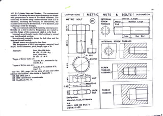
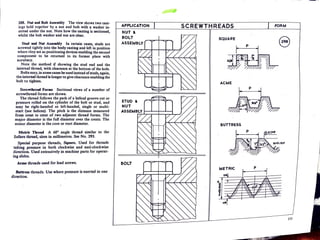
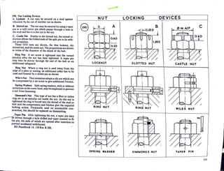
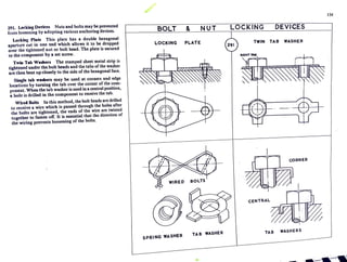
.......,., -
Part II
ENGINEERING DRAWING
RIVET AND SCR-EW
FASTENINGS
Rivets
Riveted Joints
Screwthreads
Bolts and Screws
Conventions
Locknuts
Locking Devices
- - - t t ~
r'
--
,
<I> RIVET HEADS
I
L2
-
1.6 v
2 11)
2.5 ;
>
3 a:
4
s !:;
"
8
10
12
SNAP HEAD
1.75 D
lo
~'
361s1NGLE LAP
0
ft1
I
I
I
I
tlD_:
I
I
I
I
I
II I I I•
I
I
0.60
-5
0
C
"
..J
COUNTERSUNK
FLAT HEAD
20
D
D =6 / thkkn«ss of plat«
DOUBLE FOW LAP
I
I
I
I
I
I
2D+ 6~ 1½_0 I
COUNTERSUNK
ROUNDED HEAD
I.SD
..
0.020
0-430
ZIG - ZAG LAP
$
_ _ I
l~D I
I
I
I
I
I
I
I
I
I
I
I
I
I
I
I
I
I
I
-
BUTT JOINTS
FLAT HEAD
20
1•0.25D •1 R0.6
I l I
UNIVERSAL HEAD
2 D
I. 25 D 0.40
I
•O D
STRAPS
DOUBLE
- COVER BUTT.
l
I
I
+ +
I I
I "'
I I z
QC.
l&J
I w
I I-
+ +
J
I <
I
I
+ +
I
I
I
+ + 8
I
I
I
___ , __ I. -
146
l
I
I
I
I
I
I
I
I
I
I
1 I
I
I ,
1
I
I
I
--... -------.
c:-
281. Ri-.ets A rivet is a permanent method offastening
two or more pieces of metal together. The head is pre-
formed by stamping, the second head closed by pneu-
matic hammer or hydraulically whilst red-hot. Small
rivets are closed by hammer and set. The shape and de-
tailed form ofcommon rivetheadsarcshown. Proportions
of rivets shown in terms of 0=0 of Shank.
Rivet Spacing A simple spacing based on the dia-
meter of the rivet is shown for single row lap riveting, for
double row chain riveting, for zig-zag riveting, and for
a butt joint with double cover straps, the outer row left
alte.rnate.
282. Seven riveted joints arc shown. Corner joints in
tanks may be made by bending the plate or by the use of
angle. Slides and box constructions can be built up from
standard sheet, strip, angle, channel and tee sections.
283. Joint Failures A rivet may fail by single or double
shear stress. A riveted joint may fail by the plate tearing
on the line of the rivets, or by marginal tearing, or by
elongation of the rivet holes.
Stresses in Rivets These may be calculated by using
the following formulae, where d=rivet dia, p=rivet
pitch, t = plate thickness,/,=safe tensile stress for plates,
f. = safe shear stress for rivets,.fc=safecrushing stress for
rivets or plates. (Rivets, 386 MNm- 2
to. 463 MNm- 2).
Single shear=V.=1ui2/J4.
Double shear= V~= nd2
/J2.
Crushing= Vc =dtfc-
Tea.ring resistance=(p-d)tl.
d may be found by equating f. and/C7
d = 4tfc
ef.
p may be found by equating tearing resistance and
shearing
nd2
J. d bcr f •
p = + x num o nvcts x rows.
_,,-
RIVETED
aox
FRAME
----
BOX
JOINTS
SHEET
CORNERS
FLUSH
SLIDES
-
JOINT FAILURES
-4
SINGLE SHEAR
DOUBLE SHEAR
HOLE
ELONGATION
Q
8
•
•
INAL
TING
147
286. Special Rivets for thin plates. Thin plates require
rivets which can be closed without distorting the sheet.
Aluminium and duralumin, extensively used in the air-
c.ran industry, not easy to solder and weld, a.re riveted
using rivets shown in the diagrams.
Tubular Short lengths of tube set by a shaped
plunger.
Mushroom Large head, second end closed to the flat
Snap
Flush
Mandrel
Type
shown.
Solid or part hollow. A smalJ explosive
charge detonated by a hot plu.nger enables
the rivet to be set in difficult positions.
Countersunk rivets giving a flush or level
surface. Where the sheet is stamped or
~dimpled' to form the countersinking a
strongerjoint results.
Where the plate is inaccessible from one
sid~, the hollow rivet is expanded by means
of a mandrel which is then cut off level.
(AvdeJ type).
The Chobert hollow rivet allows the
mandrel to be withdrawn after expanding
the rivet, a plug then sealing the hole if
required.
Two forms ofrivet spacinga.reshown in addition to those
previously given.. The first shows alternate spacing in the
outer row of rivets, the plate being Jess weakened. The
second shows a three, two, one arrangement for a strap
end which also tends to•weaken Jess.
See BS 641 and BS 4620 for further information on
rivets.
,,,.
THIN
~ -
TUBULAR
SNAP
•
I
PLATE
~7
1«ffi«*
MUSHROOM
'S
t•7SO
I
I
I
I
I
,.
T
FLAT
I
+ +
+ + + 4-
....... - - - - - - - - - - - - --~
+ + +
+ + j
ALTERNATE SPACING
•
RIVETING
p, I 7
~ .
OIMPtlED
AVDEL
I
FLUSH
MANDREL
$-:
@ I
I
$- t1t- $ !
©:
STRAP END
149
r
287. [SO Bolts Nuts and Washers Toe conventional
method ofdrawing the metric screw fastenings are shown
with proportions in terms of D =shank diameter. The
head may be drawn using a constructional circle 2 D in
diameter, enclosing the hexago~ or alternatively, the
chamfer circle may be drawn.first I.75 Din diameter, and
enclosing it with the hexagon.
The conventional method of rendering external screw-
threads on a stud is shown. Proportions are varied to
suit the design of the component which is to be fixed.
Internal screwthreads require the hatching to extend
over the threaded portion.
Screwtbreads assembly shows the bolt clear and the
internal thread batched.
Thread inserts are shown in clear lines.
The designation of ISO bolts require: material, head
shape, thread diameter, pitc~ length, type of fit.
Example: Steel, Hex Hd Bolts,
M 10 x 1.5 x 50- 6 g
_Steel, Hex Nuts,
M 1o·x 1.5-6 H
Types of fit for bolts are:
close fit, 4 h; medium fit 6 g;
free fit, 8 g.
Types of fit for nuts are: .
close fit, 5 H; medium 6 H;
free 7 H.
See No. 293, page 156 for table of sizes and other
relative information. Also tables in Appendix -1.
BS 3L8 1972 part 1.
8 S 1936 ISO Metric screwtbreads.
BS Handbook No. 18.
CONVENTIONS MET-RIC
METRIC BOLT
e
~CT IJJ_
+
0
N
D
s:
..a
C
"
_.
() 1.750
a
N
G
~'Ert=fJNUT
JL ....... ho1c ~0+1
I I I < 4
§CCI.. I l.-
Designation:
Material, Head, ISOdctai Is
C •CJ•
STEEL HEX HD BOLTS
M 20x 2.Sx 55
LOCK
NUT
NUTS
EXTERNAL
SCREW
THREADS
I
&
Metal
End
-
BOLTS DESIGNATION
------- - ---~---
0 II L .h
Nominal Lcnqth
-
. / ........
. .
....... /
~Plain • j.. Nut End
INTERNAL SCREW THREADS
SC-REW
THREADS
ASSE~BLY~•-
TH~EAD
INSERTS
I
,..._.
150
--~ .
- i - - , ; r ~ - •
288. Nut and Bolt Assembly The view shows two cast-
ings held together by a nut and bolt with a washer in-
serted under the nut. Note how the casting is sectioned,
whilst the bolt washer and nut arc clear.
Stud and Nut Assembly In·certain cases, studs are
screwed tightly into the body casting and left in position
where they act as positioning devices enabling the second
component to be returned to its former place with
accuracy.
Note the method if showing the stud end and the
internal thread, with clearance at the bottom of the hole.
Bolts may, in somecases be used insteadofstuds, again,
the internal thread is longer to giveclearance enabling the
bolt to tighten.
Screwthread Foram Sectional views of a number of
screwthread forms are·shown.
The thread follows the path of a helical groove cut or
pressure rolled on the cylinder of the bolt or stud, and
may be right-handed or left-handed, single or multi-
start (see helices). The pitch is the distance measured
from crest to crest of two adjacent thread forms. The
·major- diameter is the full diameter over the crests. The
minor diameter is the core or root diameter.
Mebic Thread A 60° angle thread similar to the
Sellers threa~ sizes in millimetres. See No. 293.
Special purpose threads, Square. Used for threads
taking ,pressure in both clockwise and anti-clockwise
direction. Used extensively in machine parts for operat-
ing slides.
Acme threads used for lead screws.
Battr~ threads. Use where pressure is exerted in one
direc-tion. •
APPLICATION
NUT &
BOLT
ASS.EMBLY
STUD &
NUT
ASSEMBLY I I I I I
BOLT
SCREWTHREADS FORM
SQUARE
e
r p 1
~t:l..._._...~'7
ACME
p 1
--
BUTTRESS
METRIC
~1
p
p
R•O.J'-P
,-,,.-
J
I
289. Machine Screws ISO machine screws take the
form shown in the diagrams. The proportions are given
in terms of the shank diameter.
Countersunk bead machine screws are used whena flush
finish is required on the outer surface. The head is either
slotted as shown, for use with a plain flat screwdriver or
recessed. A recessed head has a crossed closed slot're-
quiring the use of a Philips screwdriver.
Raised countersunk head screws give a small projection
of the head beyond the general surface.
Pao head screws require no countersinking and all the
head projects beyond the plate surface.
Cl!eese bead screws also give ahead projection beyond
the plate surface.
Square Head Set Screw is often used to fix collars,
gears and wheels to shafts, though the head can give·
imbalance~
Grub screws, slotted for screwdriver give a non-projec-
tion finish, and are useful for fixing collars, wheels, gib
strips.
Hexagon Socket screws have that shape recess in the
head, weakening the head less than the slot, and are
·tightened by the use of a hexagon socket key. This is a
piece of hexagonal sectioned rod with rightangled bend
to give torque.
Cap socket screws are the shape shown~ and are used
for securing covers and flanges which is counterbored to
take the caphead giving a 1lush finish.
COU11tersunk bead screws also have hexagonal sockets
for use with a key.
The ends ofmachine screws may be rolled, chamfcr~d,
radiuscd, ,coned, cup, w point, dog as suited to the special
purpose. h h
TabJes in Appendix I give the size A/F oft e exagon
socket relative to the head size of various socket.screws.
152
MACHINE SCREWS
COUNTERSUNK RAISED CSK PAN CHEESE e
20 20 20
1.75 D 1 1.75 D 0.'40 0.25D
1.60 ·i
r" .f ~0.25
0.25D-I 1.0-25D1 IJ_ I059._-<{ lo--0.25
J 0.3D
1
,1 I I 17 , . ~ - .7 r- I
I 0.6~
-'----- - - -
_.,,, ........,,...,. I'
VI 0 .ro IV I II 11 11 11
.:c
,
z
11 I I 11
l&J
D 11 I I 11 11 .J
SQ HP SET SCREW 1·1 GRUB SCREW
II CAP
SOCKET SCREWS
1.25D _1 SLOTTED I.SD
-1t: GRUB
I I I I
I I I I
~!> -}.7J
.&
o1 II o.;m 1 ~.2so II I
-R0:1SD11l']
rT'"' ~t_-_;;
I / 1.25D
SCREW
ENDS
D _11
45° II
IN
D-1
:t~
ROLLED
:c
t;
z
l&J
J
D
I II u y
CHAMFER
"
~, LV
z
l&J
_J
II u b ~up
RAOIUSED CONE
,_,,_... ·~-ti-'.""J~
290. Nut Locking Devices
A. Locknut A nut may be secured on a stud against
vibration by the use of another nut as shown.
B. Slotted not The nut may be secured by using a taper
pin 'or a split cotter pin which passes through a hole in
the stud and lies in a slot cut in the nut.
C. Castle Nat Similar to the slotted nut, the turned re-
duction allows the folded ends of the split pin to lie with-
out projection.
Three ISO nuts are shown, the thin locknut, the
slotted nut, and the castle nut. The proportions areshown
in terms of the diameter of the shank of the bolt.
Ring Nut A set screw is tightened into the turned
annulus after the nut has been tightened. A taper pin
may also be driven through the end of the bolt as an
additional safeguard.
Ring Nut Where a ring nut is used away from the
edge of a plate or casting, an additional collar has to be
used and located by a dowel pin as shown.
Wile's Nut This invention adopts a slit nut which can
be compressed by a set screw to give additional friction.
• Spring Washers Split spring washers, with or without
serrations on the outer faces, may beemployed to prevent
a nut from :Joosening.
.Simmond's Nut This type ofnut has a fibre or nylon
rii)g set in an annulus cut inside the nut. As the nut is
tightened the ring is forced into the thread of the stud or
bolt and the compression and friction give the required
locking action. Frequently used on automobile con-
struction, but should be replaced on dismantling.
)"-aper Pin After tightening the nut, a taper pin may
driven through a hole drilled and taper reamed to fit
the pin, the ends of which are opened after insertion to
prevent accidental withdrawal.
BS Handbook 16. 150Rec R 288.
-
NUT
A
a o,
V ~IJi,_l_
.,,,,, <
0.60
LOCKNUT
~--
SPRING WASHER
-
LOCKING DEVICES
B
0.2s~
..,.~--rtl-r'-<!!......._,/"Inn
-
~:>'"Ii
......... ,.-.i;:r
1.250
SLOTTED NUT
RING NUT
'/,
SIMMONDS NUT
t/) a~ A/F
CASTLE NUT
WILE J NUT
TAPER PIN
c·
. y o
PIN
153
Zit. Locking Devices Nuts and bolts may be prevented
from loosening by adopting various anchoring devices.
Locking Plate This plate has a double hexagonal
aperture cut in one end which allows it to be dropped
over the tightened nut or bolt head. The plate is secured
lo the component by a set screw.
Twin Tab Washers The stamped sheet metal strip is
tightened under the.bolt heads and the tabs of the washer
arc then bent up closely to the side ofthe hexagonal face.
Single tab washers may be used at comers and edge
locations by turning the tab over the comer of the com-
ponent. When the tab washer is used in a central position,
a hole is drilled in the component to receive the tab.
Wired Bolts In this method, the bolt heads are drilled
to receive a wire which is passed through the holes after
the bolts are tightened, the end~ of the wire are twisted
together to fasten off. lt is essential that the direction of
the wiring prevents loosening of the bolts.
BOLT & NUT
LOCKING PLATE
WIRED BOLTS
SPRING WASHER
TAB WASHER
•
154
LO-CK ING DEVICES
TWIN TAB WASHER
BENT TM
r-4-,
• I
I I ,. l i I . - • I I
CORNER
CENTRAL
TAB WASHERS
l .
-·~_,.~'-
294. Keys and Keyway.s Keys are used to fix shafts and
wheeb :ind collars together, either rigidly or with limited
o.xi::il move1nent.
Rectarrgular Key A rectangular recess is cut in both
wheel and shaft lo the proportions shown, and the key
fined.
Gfb I-lead Key This tapered key provides a rigid fixing
when driven into position. The gib head enables the key
robe withdrawn for dismantling.
Fe1rher Key The parallel-sided key is setscrewed into
:in end milled slot in the shaft. This key allows axial
movement of the wheel on the shaft while still trans-
niuing rotary movement. It also facilitates assembly of
J3 rts under difficuJt conditions.
Woodruff Key A segmental·shaped key which fits
1to o corresponding recess cut by a standard size cutter.
·his key is used on tapers and-other positions where self
ligning is required.
Saddle Keys Used for temporary fixing or light loads.
Round Keys These may either be screwed or tapered.
1e diagram shows a screwed pin, the head of which is
wn otfafter insertion to give a flush finish.
/
158
KEYS AND KEYWAYS
RECTANGULAR
¢32
GIB HEAD
simple
proportion
We ¼01A
, - iw-+6
-+--
FEATHER
8
~--+--
W up to 75 .f
I!~~ taper I: 100
Ll ~1 cp11tn 1¥1
WOODRUFF
l .- I
SADDLE
KEYS
'
W•4D
-r - .Q.
l9.
ROUND
'-T ,-E$-
HOLLOW FLAT
• i,.w
TAPER & SCREW TAPER PIN
'
I
SHAFT BEARINGS
Shafts and axles need supports lined with anti-friction
surfaces.and provision for lubrication.
The support is usually an iron casting or forging either
in one piece or split with inset bearing surfaces of bronze,
gunmetal, white metal, lead bronze, sintered metals, and
plastics, depending upon the use and conditions.
J12. Simple Bearing A simple bearing with a pressed
bronze bush, oil hole drilled in top surface.
313. Halved Bearing The support is made in two parts
bolted together, the 'brasses' are also split and located
by flanges.
314. Footstep Bearing Used for the lower end ofaver-
tical shaft. A hardened steel plate takes the weight of the
shaft. A ball thrust -race may alternatively be used, and
is shown in a later diagram.
.315. Ring Oiler Bearing A loose ring rolled by friction
from the shaft dips into an oil well and continually
lubricates the bearin·g.
Other me.thods of simple lubrication are by drip feed,
wick feed and felt oilsoaked pads.
SHAFT
SIMPLE 8
FOOTSTEP
e
BEARINGS·
8 HALVED
8
RING OILER
r·. 
·~, ..


164
_.~l Lo~1-~i-::_
,.-' . 
 •• t ·~·""
,I
•'
l
i
i
'.
I
,
I
i1
')
i
...
'
BALL BEARINGS
316. Single Row Ball Bearing The race is composed of
an inner and outer hardened grooved ring between which
run hardened steel balls carried and spaced in a cage. Ball
bearings are made in a wide range of sizes, the smallest
are found in watches whilst the largest are used in turrets
of heavy naval guns.
The simple type shown usually fits into a recess turned
in the housing and is retained by a collar or by shoulders
on the shaft. •
317. Self-aligning Ball Bearing The outer shell is
ground to the same spherical line as the housing enabling
the bearing to align itselfto the shaft line which may vary
as the load is applied. The bearing also adjusts itself to
small inexactitudes arising if the housing is incorrectly
laid.
_318. Thrust Race Ball bearings may be used to take end
thrust shown in the footstep bearing for a vertical
shaft. The axial thrust is taken by the balls carried in a
cage and moving in circular grooves ground in hardened
steel plates.
319. Spring-loaded Ball Bearing Where some axial
movement of the shaft may take place due to expansion
or load, the race may be held to the shaft by a screwed
collar and the bearing moves against a spring held in the
housing.
320. Ball Races require lubrication to avoid becoming
seized under load. The housing may be arranged to act
as an oil bath requiring sealing-shown later-or the
race may be packed with grease ~led in with spring fit
plates as shown, the lubricant lasting the life ofthe bear-
ing.
Ball races may be single or double row, designed to
take radial and/or axial thrust, and since the balls arc in
point contact with the shells much less friction is gener-
ated than with the simple journal bearing.
7 ··7
) r £- •
~Q- v-
BALL BEAR.INGS
e SINGLE ROW SELF -ALIGNING 8
THRUST RACE SPRING-LOADED
SEALED
e
8 8
165

TECHNICAL DRAWING CONVENTIONS LISTSS.pdf

  • 1.
    .......,., - Part II ENGINEERINGDRAWING RIVET AND SCR-EW FASTENINGS Rivets Riveted Joints Screwthreads Bolts and Screws Conventions Locknuts Locking Devices - - - t t ~
  • 2.
    r' -- , <I> RIVET HEADS I L2 - 1.6v 2 11) 2.5 ; > 3 a: 4 s !:; " 8 10 12 SNAP HEAD 1.75 D lo ~' 361s1NGLE LAP 0 ft1 I I I I tlD_: I I I I I II I I I• I I 0.60 -5 0 C " ..J COUNTERSUNK FLAT HEAD 20 D D =6 / thkkn«ss of plat« DOUBLE FOW LAP I I I I I I 2D+ 6~ 1½_0 I COUNTERSUNK ROUNDED HEAD I.SD .. 0.020 0-430 ZIG - ZAG LAP $ _ _ I l~D I I I I I I I I I I I I I I I I I I I - BUTT JOINTS FLAT HEAD 20 1•0.25D •1 R0.6 I l I UNIVERSAL HEAD 2 D I. 25 D 0.40 I •O D STRAPS DOUBLE - COVER BUTT. l I I + + I I I "' I I z QC. l&J I w I I- + + J I < I I + + I I I + + 8 I I I ___ , __ I. - 146 l I I I I I I I I I I 1 I I I , 1 I I I --... -------.
  • 3.
    c:- 281. Ri-.ets Arivet is a permanent method offastening two or more pieces of metal together. The head is pre- formed by stamping, the second head closed by pneu- matic hammer or hydraulically whilst red-hot. Small rivets are closed by hammer and set. The shape and de- tailed form ofcommon rivetheadsarcshown. Proportions of rivets shown in terms of 0=0 of Shank. Rivet Spacing A simple spacing based on the dia- meter of the rivet is shown for single row lap riveting, for double row chain riveting, for zig-zag riveting, and for a butt joint with double cover straps, the outer row left alte.rnate. 282. Seven riveted joints arc shown. Corner joints in tanks may be made by bending the plate or by the use of angle. Slides and box constructions can be built up from standard sheet, strip, angle, channel and tee sections. 283. Joint Failures A rivet may fail by single or double shear stress. A riveted joint may fail by the plate tearing on the line of the rivets, or by marginal tearing, or by elongation of the rivet holes. Stresses in Rivets These may be calculated by using the following formulae, where d=rivet dia, p=rivet pitch, t = plate thickness,/,=safe tensile stress for plates, f. = safe shear stress for rivets,.fc=safecrushing stress for rivets or plates. (Rivets, 386 MNm- 2 to. 463 MNm- 2). Single shear=V.=1ui2/J4. Double shear= V~= nd2 /J2. Crushing= Vc =dtfc- Tea.ring resistance=(p-d)tl. d may be found by equating f. and/C7 d = 4tfc ef. p may be found by equating tearing resistance and shearing nd2 J. d bcr f • p = + x num o nvcts x rows. _,,- RIVETED aox FRAME ---- BOX JOINTS SHEET CORNERS FLUSH SLIDES - JOINT FAILURES -4 SINGLE SHEAR DOUBLE SHEAR HOLE ELONGATION Q 8 • • INAL TING 147
  • 4.
    286. Special Rivetsfor thin plates. Thin plates require rivets which can be closed without distorting the sheet. Aluminium and duralumin, extensively used in the air- c.ran industry, not easy to solder and weld, a.re riveted using rivets shown in the diagrams. Tubular Short lengths of tube set by a shaped plunger. Mushroom Large head, second end closed to the flat Snap Flush Mandrel Type shown. Solid or part hollow. A smalJ explosive charge detonated by a hot plu.nger enables the rivet to be set in difficult positions. Countersunk rivets giving a flush or level surface. Where the sheet is stamped or ~dimpled' to form the countersinking a strongerjoint results. Where the plate is inaccessible from one sid~, the hollow rivet is expanded by means of a mandrel which is then cut off level. (AvdeJ type). The Chobert hollow rivet allows the mandrel to be withdrawn after expanding the rivet, a plug then sealing the hole if required. Two forms ofrivet spacinga.reshown in addition to those previously given.. The first shows alternate spacing in the outer row of rivets, the plate being Jess weakened. The second shows a three, two, one arrangement for a strap end which also tends to•weaken Jess. See BS 641 and BS 4620 for further information on rivets. ,,,. THIN ~ - TUBULAR SNAP • I PLATE ~7 1«ffi«* MUSHROOM 'S t•7SO I I I I I ,. T FLAT I + + + + + 4- ....... - - - - - - - - - - - - --~ + + + + + j ALTERNATE SPACING • RIVETING p, I 7 ~ . OIMPtlED AVDEL I FLUSH MANDREL $-: @ I I $- t1t- $ ! ©: STRAP END 149
  • 5.
    r 287. [SO BoltsNuts and Washers Toe conventional method ofdrawing the metric screw fastenings are shown with proportions in terms of D =shank diameter. The head may be drawn using a constructional circle 2 D in diameter, enclosing the hexago~ or alternatively, the chamfer circle may be drawn.first I.75 Din diameter, and enclosing it with the hexagon. The conventional method of rendering external screw- threads on a stud is shown. Proportions are varied to suit the design of the component which is to be fixed. Internal screwthreads require the hatching to extend over the threaded portion. Screwtbreads assembly shows the bolt clear and the internal thread batched. Thread inserts are shown in clear lines. The designation of ISO bolts require: material, head shape, thread diameter, pitc~ length, type of fit. Example: Steel, Hex Hd Bolts, M 10 x 1.5 x 50- 6 g _Steel, Hex Nuts, M 1o·x 1.5-6 H Types of fit for bolts are: close fit, 4 h; medium fit 6 g; free fit, 8 g. Types of fit for nuts are: . close fit, 5 H; medium 6 H; free 7 H. See No. 293, page 156 for table of sizes and other relative information. Also tables in Appendix -1. BS 3L8 1972 part 1. 8 S 1936 ISO Metric screwtbreads. BS Handbook No. 18. CONVENTIONS MET-RIC METRIC BOLT e ~CT IJJ_ + 0 N D s: ..a C " _. () 1.750 a N G ~'Ert=fJNUT JL ....... ho1c ~0+1 I I I < 4 §CCI.. I l.- Designation: Material, Head, ISOdctai Is C •CJ• STEEL HEX HD BOLTS M 20x 2.Sx 55 LOCK NUT NUTS EXTERNAL SCREW THREADS I & Metal End - BOLTS DESIGNATION ------- - ---~--- 0 II L .h Nominal Lcnqth - . / ........ . . ....... / ~Plain • j.. Nut End INTERNAL SCREW THREADS SC-REW THREADS ASSE~BLY~•- TH~EAD INSERTS I ,..._. 150 --~ . - i - - , ; r ~ - •
  • 6.
    288. Nut andBolt Assembly The view shows two cast- ings held together by a nut and bolt with a washer in- serted under the nut. Note how the casting is sectioned, whilst the bolt washer and nut arc clear. Stud and Nut Assembly In·certain cases, studs are screwed tightly into the body casting and left in position where they act as positioning devices enabling the second component to be returned to its former place with accuracy. Note the method if showing the stud end and the internal thread, with clearance at the bottom of the hole. Bolts may, in somecases be used insteadofstuds, again, the internal thread is longer to giveclearance enabling the bolt to tighten. Screwthread Foram Sectional views of a number of screwthread forms are·shown. The thread follows the path of a helical groove cut or pressure rolled on the cylinder of the bolt or stud, and may be right-handed or left-handed, single or multi- start (see helices). The pitch is the distance measured from crest to crest of two adjacent thread forms. The ·major- diameter is the full diameter over the crests. The minor diameter is the core or root diameter. Mebic Thread A 60° angle thread similar to the Sellers threa~ sizes in millimetres. See No. 293. Special purpose threads, Square. Used for threads taking ,pressure in both clockwise and anti-clockwise direction. Used extensively in machine parts for operat- ing slides. Acme threads used for lead screws. Battr~ threads. Use where pressure is exerted in one direc-tion. • APPLICATION NUT & BOLT ASS.EMBLY STUD & NUT ASSEMBLY I I I I I BOLT SCREWTHREADS FORM SQUARE e r p 1 ~t:l..._._...~'7 ACME p 1 -- BUTTRESS METRIC ~1 p p R•O.J'-P ,-,,.- J
  • 7.
    I 289. Machine ScrewsISO machine screws take the form shown in the diagrams. The proportions are given in terms of the shank diameter. Countersunk bead machine screws are used whena flush finish is required on the outer surface. The head is either slotted as shown, for use with a plain flat screwdriver or recessed. A recessed head has a crossed closed slot're- quiring the use of a Philips screwdriver. Raised countersunk head screws give a small projection of the head beyond the general surface. Pao head screws require no countersinking and all the head projects beyond the plate surface. Cl!eese bead screws also give ahead projection beyond the plate surface. Square Head Set Screw is often used to fix collars, gears and wheels to shafts, though the head can give· imbalance~ Grub screws, slotted for screwdriver give a non-projec- tion finish, and are useful for fixing collars, wheels, gib strips. Hexagon Socket screws have that shape recess in the head, weakening the head less than the slot, and are ·tightened by the use of a hexagon socket key. This is a piece of hexagonal sectioned rod with rightangled bend to give torque. Cap socket screws are the shape shown~ and are used for securing covers and flanges which is counterbored to take the caphead giving a 1lush finish. COU11tersunk bead screws also have hexagonal sockets for use with a key. The ends ofmachine screws may be rolled, chamfcr~d, radiuscd, ,coned, cup, w point, dog as suited to the special purpose. h h TabJes in Appendix I give the size A/F oft e exagon socket relative to the head size of various socket.screws. 152 MACHINE SCREWS COUNTERSUNK RAISED CSK PAN CHEESE e 20 20 20 1.75 D 1 1.75 D 0.'40 0.25D 1.60 ·i r" .f ~0.25 0.25D-I 1.0-25D1 IJ_ I059._-<{ lo--0.25 J 0.3D 1 ,1 I I 17 , . ~ - .7 r- I I 0.6~ -'----- - - - _.,,, ........,,...,. I' VI 0 .ro IV I II 11 11 11 .:c , z 11 I I 11 l&J D 11 I I 11 11 .J SQ HP SET SCREW 1·1 GRUB SCREW II CAP SOCKET SCREWS 1.25D _1 SLOTTED I.SD -1t: GRUB I I I I I I I I ~!> -}.7J .& o1 II o.;m 1 ~.2so II I -R0:1SD11l'] rT'"' ~t_-_;; I / 1.25D SCREW ENDS D _11 45° II IN D-1 :t~ ROLLED :c t; z l&J J D I II u y CHAMFER " ~, LV z l&J _J II u b ~up RAOIUSED CONE ,_,,_... ·~-ti-'.""J~
  • 8.
    290. Nut LockingDevices A. Locknut A nut may be secured on a stud against vibration by the use of another nut as shown. B. Slotted not The nut may be secured by using a taper pin 'or a split cotter pin which passes through a hole in the stud and lies in a slot cut in the nut. C. Castle Nat Similar to the slotted nut, the turned re- duction allows the folded ends of the split pin to lie with- out projection. Three ISO nuts are shown, the thin locknut, the slotted nut, and the castle nut. The proportions areshown in terms of the diameter of the shank of the bolt. Ring Nut A set screw is tightened into the turned annulus after the nut has been tightened. A taper pin may also be driven through the end of the bolt as an additional safeguard. Ring Nut Where a ring nut is used away from the edge of a plate or casting, an additional collar has to be used and located by a dowel pin as shown. Wile's Nut This invention adopts a slit nut which can be compressed by a set screw to give additional friction. • Spring Washers Split spring washers, with or without serrations on the outer faces, may beemployed to prevent a nut from :Joosening. .Simmond's Nut This type ofnut has a fibre or nylon rii)g set in an annulus cut inside the nut. As the nut is tightened the ring is forced into the thread of the stud or bolt and the compression and friction give the required locking action. Frequently used on automobile con- struction, but should be replaced on dismantling. )"-aper Pin After tightening the nut, a taper pin may driven through a hole drilled and taper reamed to fit the pin, the ends of which are opened after insertion to prevent accidental withdrawal. BS Handbook 16. 150Rec R 288. - NUT A a o, V ~IJi,_l_ .,,,,, < 0.60 LOCKNUT ~-- SPRING WASHER - LOCKING DEVICES B 0.2s~ ..,.~--rtl-r'-<!!......._,/"Inn - ~:>'"Ii ......... ,.-.i;:r 1.250 SLOTTED NUT RING NUT '/, SIMMONDS NUT t/) a~ A/F CASTLE NUT WILE J NUT TAPER PIN c· . y o PIN 153
  • 9.
    Zit. Locking DevicesNuts and bolts may be prevented from loosening by adopting various anchoring devices. Locking Plate This plate has a double hexagonal aperture cut in one end which allows it to be dropped over the tightened nut or bolt head. The plate is secured lo the component by a set screw. Twin Tab Washers The stamped sheet metal strip is tightened under the.bolt heads and the tabs of the washer arc then bent up closely to the side ofthe hexagonal face. Single tab washers may be used at comers and edge locations by turning the tab over the comer of the com- ponent. When the tab washer is used in a central position, a hole is drilled in the component to receive the tab. Wired Bolts In this method, the bolt heads are drilled to receive a wire which is passed through the holes after the bolts are tightened, the end~ of the wire are twisted together to fasten off. lt is essential that the direction of the wiring prevents loosening of the bolts. BOLT & NUT LOCKING PLATE WIRED BOLTS SPRING WASHER TAB WASHER • 154 LO-CK ING DEVICES TWIN TAB WASHER BENT TM r-4-, • I I I ,. l i I . - • I I CORNER CENTRAL TAB WASHERS l . -·~_,.~'-
  • 10.
    294. Keys andKeyway.s Keys are used to fix shafts and wheeb :ind collars together, either rigidly or with limited o.xi::il move1nent. Rectarrgular Key A rectangular recess is cut in both wheel and shaft lo the proportions shown, and the key fined. Gfb I-lead Key This tapered key provides a rigid fixing when driven into position. The gib head enables the key robe withdrawn for dismantling. Fe1rher Key The parallel-sided key is setscrewed into :in end milled slot in the shaft. This key allows axial movement of the wheel on the shaft while still trans- niuing rotary movement. It also facilitates assembly of J3 rts under difficuJt conditions. Woodruff Key A segmental·shaped key which fits 1to o corresponding recess cut by a standard size cutter. ·his key is used on tapers and-other positions where self ligning is required. Saddle Keys Used for temporary fixing or light loads. Round Keys These may either be screwed or tapered. 1e diagram shows a screwed pin, the head of which is wn otfafter insertion to give a flush finish. / 158 KEYS AND KEYWAYS RECTANGULAR ¢32 GIB HEAD simple proportion We ¼01A , - iw-+6 -+-- FEATHER 8 ~--+-- W up to 75 .f I!~~ taper I: 100 Ll ~1 cp11tn 1¥1 WOODRUFF l .- I SADDLE KEYS ' W•4D -r - .Q. l9. ROUND '-T ,-E$- HOLLOW FLAT • i,.w TAPER & SCREW TAPER PIN '
  • 11.
    I SHAFT BEARINGS Shafts andaxles need supports lined with anti-friction surfaces.and provision for lubrication. The support is usually an iron casting or forging either in one piece or split with inset bearing surfaces of bronze, gunmetal, white metal, lead bronze, sintered metals, and plastics, depending upon the use and conditions. J12. Simple Bearing A simple bearing with a pressed bronze bush, oil hole drilled in top surface. 313. Halved Bearing The support is made in two parts bolted together, the 'brasses' are also split and located by flanges. 314. Footstep Bearing Used for the lower end ofaver- tical shaft. A hardened steel plate takes the weight of the shaft. A ball thrust -race may alternatively be used, and is shown in a later diagram. .315. Ring Oiler Bearing A loose ring rolled by friction from the shaft dips into an oil well and continually lubricates the bearin·g. Other me.thods of simple lubrication are by drip feed, wick feed and felt oilsoaked pads. SHAFT SIMPLE 8 FOOTSTEP e BEARINGS· 8 HALVED 8 RING OILER r·. ·~, .. 164 _.~l Lo~1-~i-::_ ,.-' . •• t ·~·"" ,I •'
  • 12.
    l i i '. I , I i1 ') i ... ' BALL BEARINGS 316. SingleRow Ball Bearing The race is composed of an inner and outer hardened grooved ring between which run hardened steel balls carried and spaced in a cage. Ball bearings are made in a wide range of sizes, the smallest are found in watches whilst the largest are used in turrets of heavy naval guns. The simple type shown usually fits into a recess turned in the housing and is retained by a collar or by shoulders on the shaft. • 317. Self-aligning Ball Bearing The outer shell is ground to the same spherical line as the housing enabling the bearing to align itselfto the shaft line which may vary as the load is applied. The bearing also adjusts itself to small inexactitudes arising if the housing is incorrectly laid. _318. Thrust Race Ball bearings may be used to take end thrust shown in the footstep bearing for a vertical shaft. The axial thrust is taken by the balls carried in a cage and moving in circular grooves ground in hardened steel plates. 319. Spring-loaded Ball Bearing Where some axial movement of the shaft may take place due to expansion or load, the race may be held to the shaft by a screwed collar and the bearing moves against a spring held in the housing. 320. Ball Races require lubrication to avoid becoming seized under load. The housing may be arranged to act as an oil bath requiring sealing-shown later-or the race may be packed with grease ~led in with spring fit plates as shown, the lubricant lasting the life ofthe bear- ing. Ball races may be single or double row, designed to take radial and/or axial thrust, and since the balls arc in point contact with the shells much less friction is gener- ated than with the simple journal bearing. 7 ··7 ) r £- • ~Q- v- BALL BEAR.INGS e SINGLE ROW SELF -ALIGNING 8 THRUST RACE SPRING-LOADED SEALED e 8 8 165