Downloaded 15 times


![11
E-ClassData
Drive Pulley Shaft Detail Worksheet
Pulley Identification_ ____________________________________
Belt Width____________________________________________
Pulley Diameter Dimension OD____________________________
Pulley Face Width Dimension FW___________________________
Crown Face or Flat Face__________________________________
Hub Type_____________________________________________
Lagging Thickness & Type_________________________________
Drive Side (Right or Left)__________________________________
[Standing at Tail Looking to Head]
Pulley Offset Dimension O________________________________
Number of Keyseats_____________________________________
Pulley Keyseat Size_____________________________________
Shaft Material_ ________________________________________
Major Shaft Diameter Dimension D_________________________
Overall Shaft Length Dimension OAL________________________
Shaft Diameter at Hubs___________________________________
Shaft Diameter at Bearings________________________________
Shaft Diameter at Reducer Dimension R______________________
Drive Key Size x Length Dimension DK_______________________
Reducer Journal Length Dimension JL_______________________
Shaft Diameter at Backstop Dimension B_____________________
Key Size x Length Dimension BK_ __________________________
Bearing Centers Dimension BC____________________________
Bearing Type__________________________________________
Shaft Drill and Tap (Size & Qty)_ ____________________________
JL
D
O
DK
OD
FW
RB
BK
OAL
BC
Components Division
P.O. Box 654
Highway 28 East
Morris, MN 56267
DATEDRAWN BY ASSEMBLY NO.
DRAWING NUMBER REV
2d pulley
FILE
SCALE (UNO) CHECKED SIZE
B
THIS DRAWING IS THE PROPERTY
OF SUPERIOR INDUSTRIES. IT IS
NOT TO BE REPRODUCED IN ANY
MANNER WITHOUT PERMISSION.
ALL DIMENSIONS IN INCHES (UNO)
TOLERANCES UNLESS
OTHERWISE NOTED:
FRACTIONAL: 1/32
ANGULAR: .1
DECIMAL: 0.0 .1
0.00 .05
0.000 .005
0.0000 .0020
HOLE : 1/32
SYTELINE PART NO.WEIGHT
MATERIAL
NTSFORMAT
SOLIDWORKS
THIRD
ANGLE
PROJECTION
Non-Drive Pulley Assembly Details
Pulley Identification____________________________________
Belt Width____________________________________________
Drum Pulley or Wing Pulley________________________________
Pulley Diameter Dimension OD____________________________
Pulley Face Width Dimension FW___________________________
Crown Face or Flat Face _________________________________
Hub Type_____________________________________________
Lagging Thickness and Type_______________________________
Pulley Offset Dimension O________________________________
Shaft Material_ ________________________________________
Major Shaft Diameter Dimension D_________________________
Overall Shaft Length Dimension OAL________________________
Number of Keyseats_____________________________________
Keyseat Size__________________________________________
Shaft Material_ ________________________________________
Shaft Diameter at Hubs___________________________________
Shaft Diameter at Bearings________________________________
Shaft Diameter on Ends (if stub shaft)_ _______________________
Bearing Centers Dimension BC____________________________
Bearing Type__________________________________________
Shaft Drill and Tap (Size & Qty)_ ____________________________
OAL
DOD
FW O
BC
Components Division
P.O. Box 654
Highway 28 East
Morris, MN 56267
DATEDRAWN BY ASSEMBLY NO.
DRAWING NUMBER REV
2d.idler puleey
FILE
SCALE (UNO) CHECKED SIZE
B
THIS DRAWING IS THE PROPERTY
OF SUPERIOR INDUSTRIES. IT IS
NOT TO BE REPRODUCED IN ANY
MANNER WITHOUT PERMISSION.
ALL DIMENSIONS IN INCHES (UNO)
TOLERANCES UNLESS
OTHERWISE NOTED:
FRACTIONAL: 1/32
ANGULAR: .1
DECIMAL: 0.0 .1
0.00 .05
0.000 .005
0.0000 .0020
HOLE : 1/32
SYTELINE PART NO.WEIGHT
MATERIAL
NTSFORMAT
SOLIDWORKS
THIRD
ANGLE
PROJECTION
Figure 2.2
Figure 2.1](https://image.slidesharecdn.com/pulley-catalog-11-05-low-180629052109/85/Pulley-catalog-11-05-low-11-320.jpg)


![A-33
Lagging Weights
Weight Information – Vulcanized Rubber Lagging Weights
Chart continued...
DIA. LAGGING THICKNESS
WEIGHTS / FACE WIDTH (INCHES)
10 12 14 16 18 20 22 24 26 30 32
6"
1/4
3/8
1/2
3
4
5
3
5
6
4
6
8
4
7
9
5
7
10
6
8
11
7
9
12
7
10
14
8
11
15
10
13
17
10
14
19
8"
1/4
3/8
1/2
4
5
7
4
6
8
5
7
10
6
9
11
7
10
13
8
11
14
9
12
16
10
14
18
11
15
19
13
18
23
14
19
25
10"
1/4
3/8
1/2
4
6
8
5
8
10
6
9
12
7
11
14
8
12
16
10
14
18
11
15
20
12
17
22
13
18
24
16
22
28
17
23
30
12"
1/4
3/8
1/2
5
8
10
6
9
12
8
11
14
9
13
17
10
14
19
11
16
21
13
18
26
14
20
26
16
22
28
19
26
33
20
28
36
14"
1/4
3/8
1/2
6
9
12
7
11
14
9
13
17
10
15
19
12
17
22
13
19
25
15
21
27
16
23
30
18
25
33
22
30
39
23
32
42
16"
1/4
3/8
1/2
7
10
13
8
12
16
10
14
19
12
17
22
13
19
25
15
21
28
17
24
31
19
26
34
21
29
37
25
34
44
27
37
47
18"
1/4
3/8
1/2
8
11
15
9
14
18
11
16
21
13
19
25
15
21
28
17
24
31
19
27
35
21
30
38
23
33
42
28
38
49
30
44
53
20"
1/4
3/8
1/2
9
13
17
10
15
20
12
18
24
15
21
27
17
24
31
19
27
35
21
30
39
23
33
43
26
36
46
31
43
55
33
46
59
24"
1/4
3/8
1/2
10
15
20
13
18
24
15
22
29
17
25
33
20
28
37
22
32
42
25
36
46
28
40
51
31
43
56
37
51
65
40
55
70
30"
1/4
3/8
1/2
13
19
25
16
23
30
19
27
35
22
31
41
25
35
46
28
40
52
31
44
57
35
49
63
38
54
69
46
63
81
50
68
87
36"
1/4
3/8
1/2
15
22
29
19
27
36
22
32
42
26
37
49
28
42
55
34
48
62
38
53
69
42
59
76
46
64
83
55
76
97
59
82
105
DIA. LAGGING THICKNESS
WEIGHTS / FACE WIDTH (INCHES)
36 38 40 44 46 51 54 57 60 63 66
6"
1/4
3/8
1/2
12
17
22
13
18
23
14
19
24
16
21
27
17
23
29
19
26
33
21
28
35
22
30
38
24
32
40
26
34
43
27
36
45
8"
1/4
3/8
1/2
16
22
28
17
23
30
18
25
32
21
28
36
22
30
38
25
34
43
27
36
46
29
39
49
31
42
52
34
44
55
36
47
59
10"
1/4
3/8
1/2
20
27
35
21
29
37
22
31
39
25
35
44
27
37
46
31
42
52
34
45
56
36
48
60
39
51
64
42
55
68
44
58
72
12"
1/4
3/8
1/2
23
32
41
25
34
44
27
37
47
30
41
52
32
44
55
37
50
62
40
53
67
43
57
72
46
61
76
50
65
81
53
69
86
14"
1/4
3/8
1/2
27
37
48
29
40
51
31
42
54
35
48
60
37
50
64
43
57
72
46
62
77
50
66
83
54
71
88
58
76
94
61
80
100
16"
1/4
3/8
1/2
31
43
54
33
45
58
35
48
61
40
54
69
43
57
73
49
65
82
53
70
88
57
75
94
61
81
100
66
86
107
70
91
113
18"
1/4
3/8
1/2
35
48
61
37
51
65
40
54
69
45
61
77
48
64
81
55
73
92
59
79
99
64
85
105
69
90
112
73
96
119
78
102
127
20"
1/4
3/8
1/2
39
53
67
41
56
72
44
60
76
50
68
85
53
71
90
61
81
102
66
87
110
71
94
117
76
100
124
81
107
132
87
113
140
24"
1/4
3/8
1/2
46
63
80
49
67
86
53
72
91
60
81
102
63
85
107
73
97
122
79
104
130
85
112
140
91
120
149
97
128
158
104
136
167
30"
1/4
3/8
1/2
57
79
100
62
84
107
66
90
113
75
101
127
79
106
134
91
121
151
98
130
162
106
140
174
113
149
185
121
159
196
130
169
208
36"
1/4
3/8
1/2
69
94
118
74
101
128
79
107
135
89
120
152
95
127
160
109
145
181
118
156
194
127
167
207
136
178
221
145
190
235
155
202
249
LaggingWeights
If grooved pulley (for 3/8” or 1/2” thickness) - take weight in chart and [Multiply by 0.95]
Table 10.1 Crowned Drum](https://image.slidesharecdn.com/pulley-catalog-11-05-low-180629052109/85/Pulley-catalog-11-05-low-33-320.jpg)


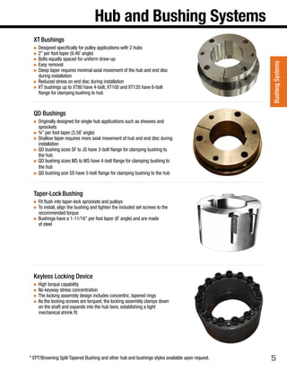
This document provides technical specifications and details for various pulley products, including: 1. An overview of Superior's product range including CEMA, mine duty, super duty, and Chevron wing pulleys in various duty classes. 2. Dimensions for XT and QD bushing systems used with pulleys. 3. Tables and figures with pulley specifications such as bushing locations, pulley assemblies, pulley classes, pulley drawings, torque values, weights, formulas, and other technical information. The document serves as a reference guide for pulley specifications, components, and technical details. It includes specifications for different pulley types, duty classes, components, and formulas.


