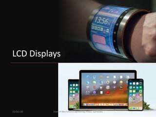
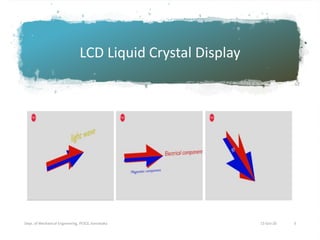
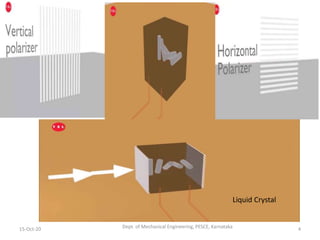
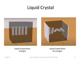
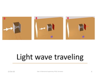
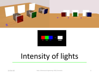
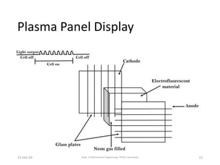
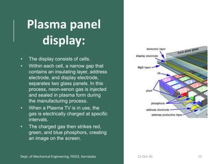
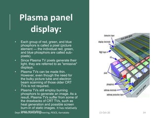
by
Mr. Siddesh Kumar N M
Assistant Professor
Department of Mechanical Engg.
P. E. S. College of Engineering
Mandya, Karnataka, India.
Dept. of Mechanical Engineering, PESCE. 1
CAD/CAM
P18ME551
15-Oct-20
LCD Displays
15-Oct-20 Dept. of Mechanical Engineering, PESCE, Karnataka 2
LCD Liquid Crystal Display
15-Oct-20Dept. of Mechanical Engineering, PESCE, Karnataka 3
15-Oct-20 Dept. of Mechanical Engineering, PESCE, Karnataka 4
Liquid Crystal
Liquid Crystal
15-Oct-20 Dept. of Mechanical Engineering, PESCE, Karnataka 5
Liquid Crystal when
energies
Liquid Crystal when
de-energies
Light wave traveling
15-Oct-20 Dept. of Mechanical Engineering, PESCE, Karnataka 6
Intensity of lights
15-Oct-20 Dept. of Mechanical Engineering, PESCE, Karnataka 7
LCD Display
15-Oct-20 Dept. of Mechanical Engineering, PESCE, Karnataka 8
Dept. of Mechanical Engineering, PESCE. 9 15-Oct-20
Fig: Liquid crystal display (LCD)
Liquid crystal display (LCD):
• Solids act the way they do because their molecules always
maintain their orientation and stay in the same position with
respect to one another.
• The molecules in liquids are just the opposite: They can
change their orientation and move anywhere in the liquid. But
there are some substances that can exist in an odd state that
is sort of like a liquid and sort of like a solid.
• When they are in this state, their molecules tend to maintain
their orientation, like the molecules in a solid, but also move
around to different positions, like the molecules in a liquid.
• This means that liquid crystals are neither a solid nor a liquid.
• Each of the pixels is an LCD panel, is a multi-layer sandwich
supported by a fluorescent backlight.
15-Oct-20 Dept. of Mechanical Engineering, PESCE, Karnataka 10
Liquid crystal display (LCD):
• At the two far ends of the LCD panel are non-alkaline, transparent glass
substrates.
• The glass substrates are attached to polarizer film that transmits or
absorbs a specific component of polarized light.
• In between the two glass substrates is layer of the nematic phase liquid
crystals. There is also a color filter containing the three primary colors
(red, green and blue).
• Each of the polarized glass is arranged at right angles to each other, so
when electric current was passed through the LCD panel, the liquid
crystals are aligned with the first polarized glass encountered and will
make a 90o twist when approaching the other polarized glass at the end.
When this happens, the light from the fluorescent backlight is able to pass
through and thus giving us a lighted pixel on the monitor.
• When there is no electric current, the liquid crystals will not twist and thus
the light will not pass through and a black pixel will be shown
15-Oct-20 Dept. of Mechanical Engineering, PESCE, Karnataka 11
Plasma Panel Display
15-Oct-20 Dept. of Mechanical Engineering, PESCE, Karnataka 12
Plasma panel
display:
• The display consists of cells.
• Within each cell, a narrow gap that
contains an insulating layer, address
electrode, and display electrode,
separates two glass panels. In this
process, neon-xenon gas is injected
and sealed in plasma form during
the manufacturing process.
• When a Plasma TV is in use, the
gas is electrically charged at specific
intervals.
• The charged gas then strikes red,
green, and blue phosphors, creating
an image on the screen.
Dept. of Mechanical Engineering, PESCE, Karnataka 15-Oct-20 13
Plasma panel
display:
• Each group of red, green, and blue
phosphors is called a pixel (picture
element — the individual red, green,
and blue phosphors are called sub-
pixels).
• Since Plasma TV pixels generate their
light, they are referred to as "emissive"
displays.
• Plasma TVs can be made thin.
However, even though the need for
the bulky picture tube and electron
beam scanning of those older CRT
TVs is not required,
• Plasma TVs still employ burning
phosphors to generate an image. As a
result, Plasma TVs suffer from some of
the drawbacks of CRT TVs, such as
heat generation and possible screen
burn-in of static images. It has relatively
poor resolution.Dept. of Mechanical Engineering, PESCE, Karnataka 15-Oct-20 14
Dept. of Mechanical Engineering, PESCE. 15 15-Oct-20
Light Emitting Diode (LED) display Working principle is same as LCD monitor and only
difference is instead of fluorescent backlight LEDs are used. Resolution is high, images are
sharp and clear.
Storage Devices: Permanent storage of programs and of Data generated during various
sessions of CAD/CAM require a large amount of storage space.
The various devices used are
1. Floppy disks 2. Hard disks 3. Magnetic tape cartridges 4. Compact disks 5. DVD 6. Blue
Ray disks 7. Pen drives 8. External hard disks 9. Solid-state device 10. Microchips

Lcd and plasma

  • 1.
    by Mr. Siddesh KumarN M Assistant Professor Department of Mechanical Engg. P. E. S. College of Engineering Mandya, Karnataka, India. Dept. of Mechanical Engineering, PESCE. 1 CAD/CAM P18ME551 15-Oct-20
  • 2.
    LCD Displays 15-Oct-20 Dept.of Mechanical Engineering, PESCE, Karnataka 2
  • 3.
    LCD Liquid CrystalDisplay 15-Oct-20Dept. of Mechanical Engineering, PESCE, Karnataka 3
  • 4.
    15-Oct-20 Dept. ofMechanical Engineering, PESCE, Karnataka 4 Liquid Crystal
  • 5.
    Liquid Crystal 15-Oct-20 Dept.of Mechanical Engineering, PESCE, Karnataka 5 Liquid Crystal when energies Liquid Crystal when de-energies
  • 6.
    Light wave traveling 15-Oct-20Dept. of Mechanical Engineering, PESCE, Karnataka 6
  • 7.
    Intensity of lights 15-Oct-20Dept. of Mechanical Engineering, PESCE, Karnataka 7
  • 8.
    LCD Display 15-Oct-20 Dept.of Mechanical Engineering, PESCE, Karnataka 8
  • 9.
    Dept. of MechanicalEngineering, PESCE. 9 15-Oct-20 Fig: Liquid crystal display (LCD)
  • 10.
    Liquid crystal display(LCD): • Solids act the way they do because their molecules always maintain their orientation and stay in the same position with respect to one another. • The molecules in liquids are just the opposite: They can change their orientation and move anywhere in the liquid. But there are some substances that can exist in an odd state that is sort of like a liquid and sort of like a solid. • When they are in this state, their molecules tend to maintain their orientation, like the molecules in a solid, but also move around to different positions, like the molecules in a liquid. • This means that liquid crystals are neither a solid nor a liquid. • Each of the pixels is an LCD panel, is a multi-layer sandwich supported by a fluorescent backlight. 15-Oct-20 Dept. of Mechanical Engineering, PESCE, Karnataka 10
  • 11.
    Liquid crystal display(LCD): • At the two far ends of the LCD panel are non-alkaline, transparent glass substrates. • The glass substrates are attached to polarizer film that transmits or absorbs a specific component of polarized light. • In between the two glass substrates is layer of the nematic phase liquid crystals. There is also a color filter containing the three primary colors (red, green and blue). • Each of the polarized glass is arranged at right angles to each other, so when electric current was passed through the LCD panel, the liquid crystals are aligned with the first polarized glass encountered and will make a 90o twist when approaching the other polarized glass at the end. When this happens, the light from the fluorescent backlight is able to pass through and thus giving us a lighted pixel on the monitor. • When there is no electric current, the liquid crystals will not twist and thus the light will not pass through and a black pixel will be shown 15-Oct-20 Dept. of Mechanical Engineering, PESCE, Karnataka 11
  • 12.
    Plasma Panel Display 15-Oct-20Dept. of Mechanical Engineering, PESCE, Karnataka 12
  • 13.
    Plasma panel display: • Thedisplay consists of cells. • Within each cell, a narrow gap that contains an insulating layer, address electrode, and display electrode, separates two glass panels. In this process, neon-xenon gas is injected and sealed in plasma form during the manufacturing process. • When a Plasma TV is in use, the gas is electrically charged at specific intervals. • The charged gas then strikes red, green, and blue phosphors, creating an image on the screen. Dept. of Mechanical Engineering, PESCE, Karnataka 15-Oct-20 13
  • 14.
    Plasma panel display: • Eachgroup of red, green, and blue phosphors is called a pixel (picture element — the individual red, green, and blue phosphors are called sub- pixels). • Since Plasma TV pixels generate their light, they are referred to as "emissive" displays. • Plasma TVs can be made thin. However, even though the need for the bulky picture tube and electron beam scanning of those older CRT TVs is not required, • Plasma TVs still employ burning phosphors to generate an image. As a result, Plasma TVs suffer from some of the drawbacks of CRT TVs, such as heat generation and possible screen burn-in of static images. It has relatively poor resolution.Dept. of Mechanical Engineering, PESCE, Karnataka 15-Oct-20 14
  • 15.
    Dept. of MechanicalEngineering, PESCE. 15 15-Oct-20 Light Emitting Diode (LED) display Working principle is same as LCD monitor and only difference is instead of fluorescent backlight LEDs are used. Resolution is high, images are sharp and clear. Storage Devices: Permanent storage of programs and of Data generated during various sessions of CAD/CAM require a large amount of storage space. The various devices used are 1. Floppy disks 2. Hard disks 3. Magnetic tape cartridges 4. Compact disks 5. DVD 6. Blue Ray disks 7. Pen drives 8. External hard disks 9. Solid-state device 10. Microchips