Downloaded 470 times
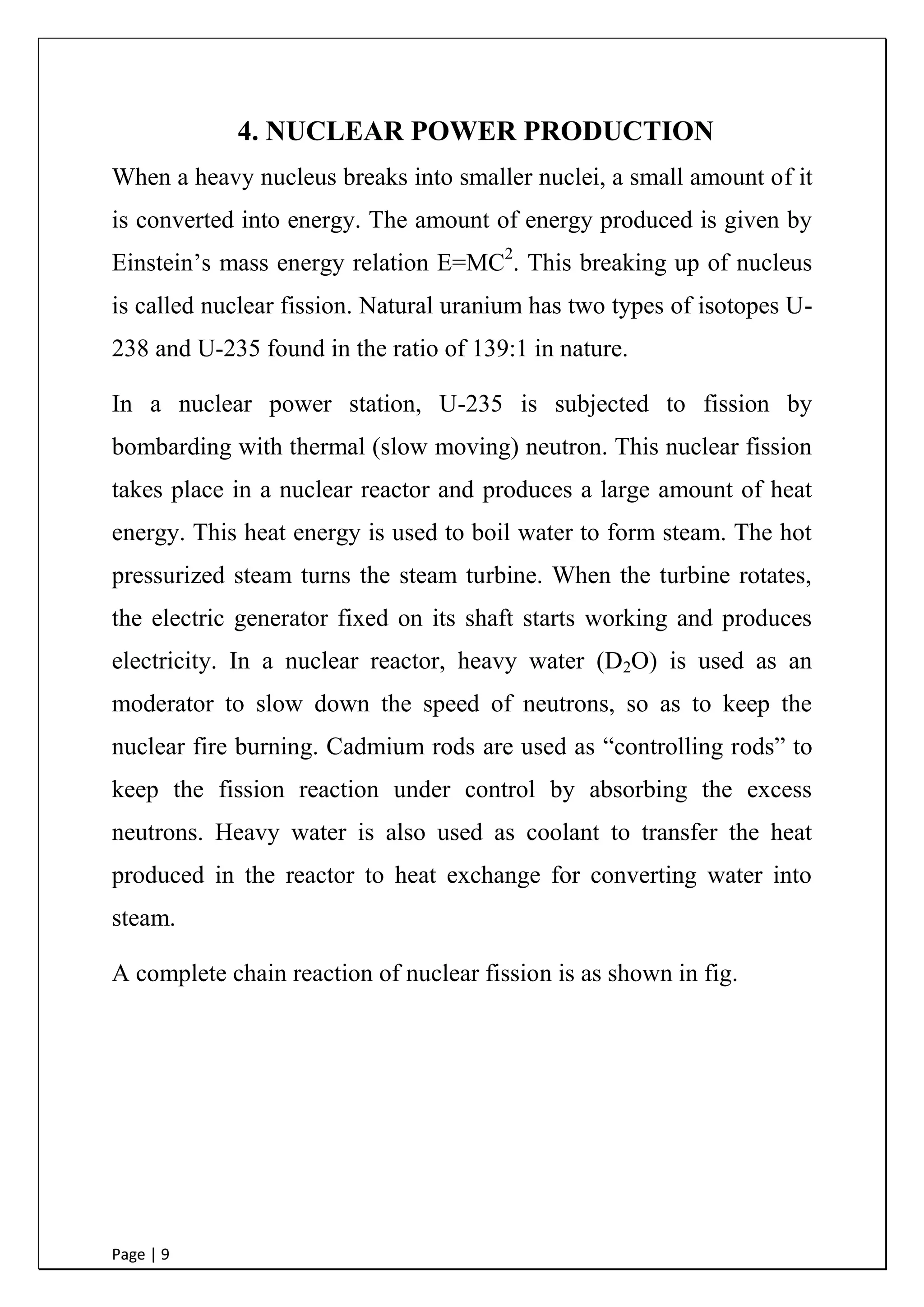
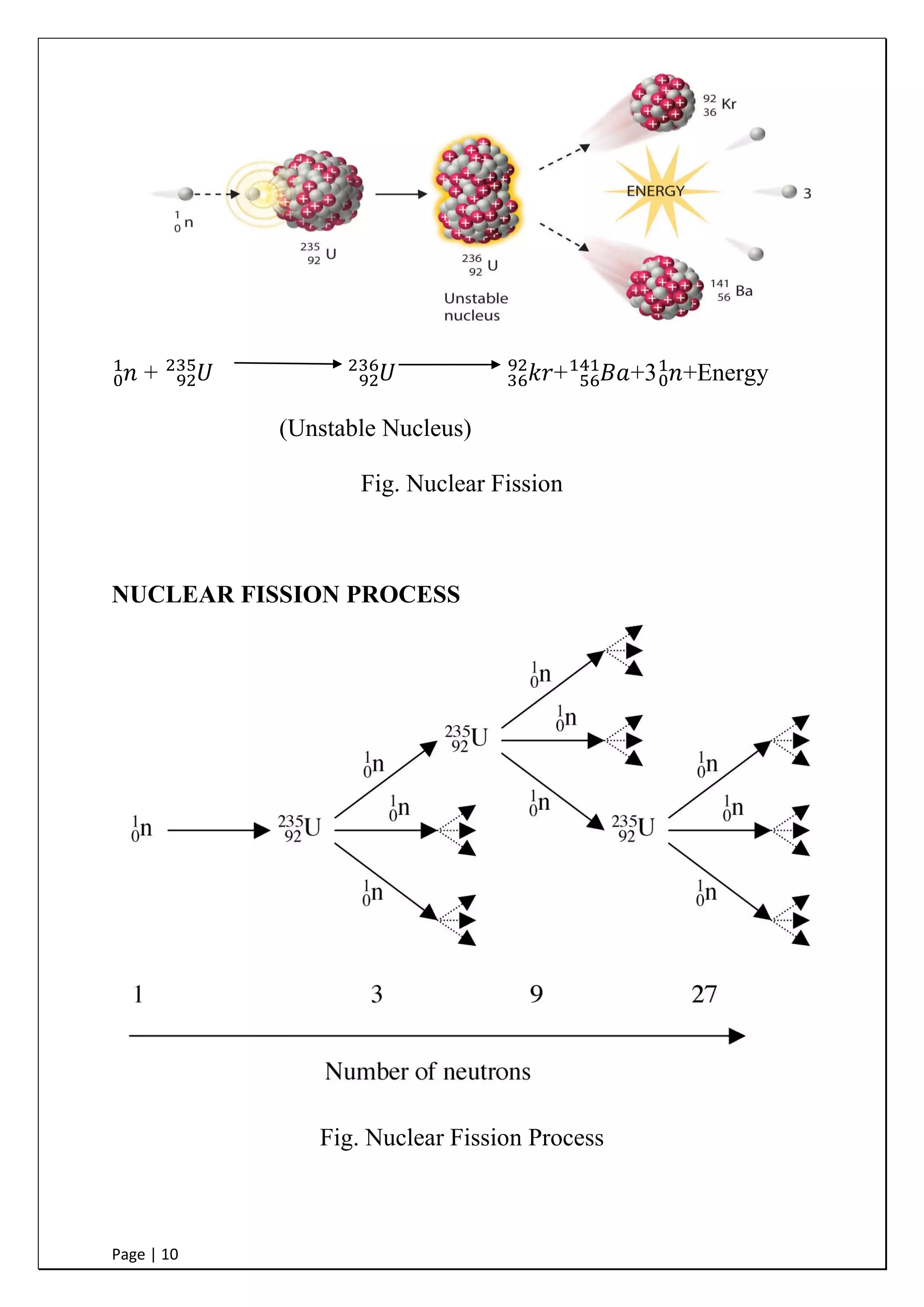
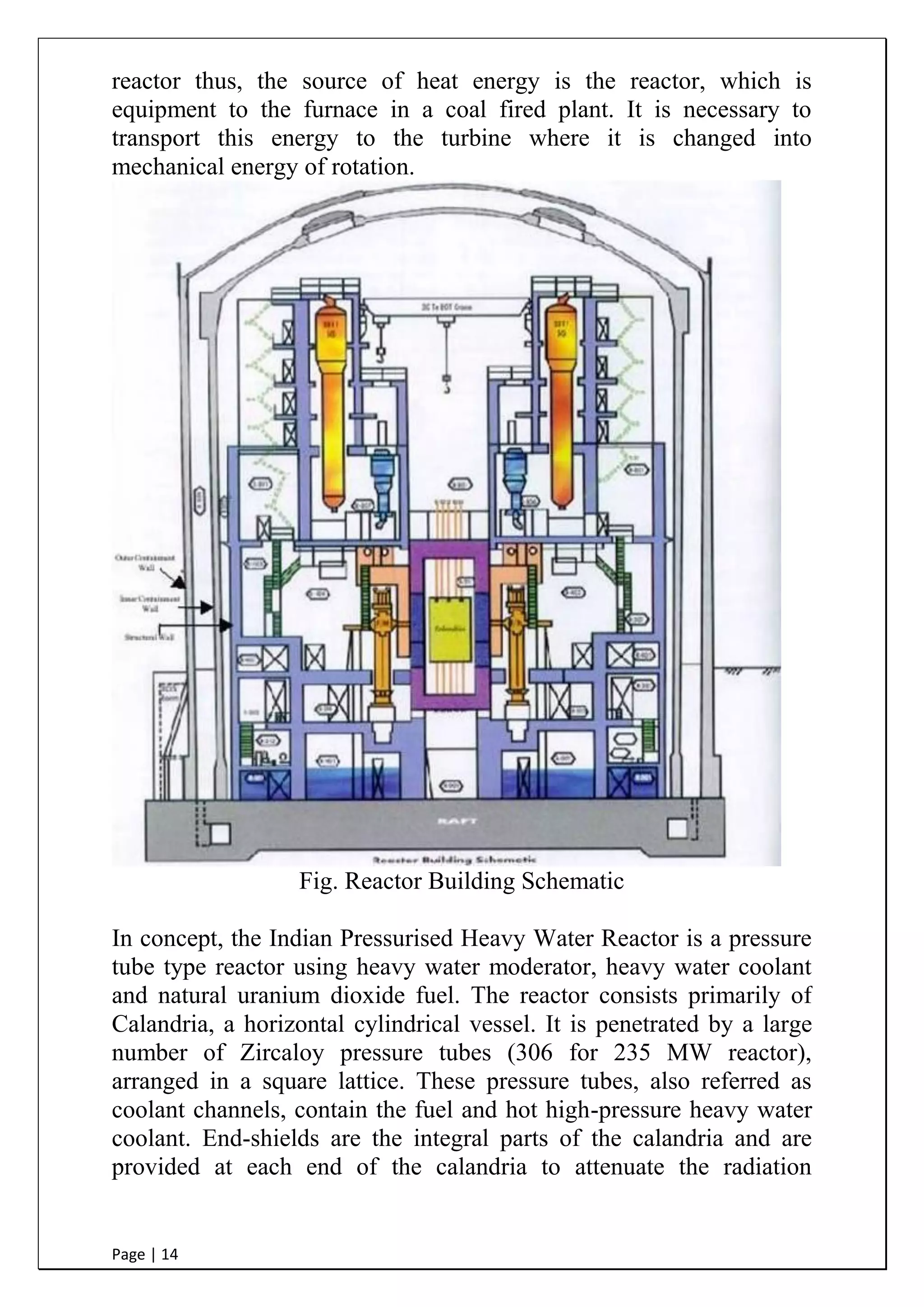

This document is a summer training report submitted by Lekha Raj Meena, a final year electrical engineering student, after completing a 60 day training program at the Nuclear Power Corporation of India Limited (NPCIL) facility in Rawatbhata, Rajasthan. It provides an overview of NPCIL and the Rajasthan Atomic Power Station, where the student received hands-on experience observing the various systems and equipment used in nuclear power generation, helping to understand concepts studied in textbooks. The report includes sections on nuclear power production processes, India's nuclear power program, the main components of a nuclear power plant, different reactor types, site selection criteria, waste management, safety, and an environmental survey lab.


![industry 4.0-Revolution-PowerPoint-Templates [Autosaved].pptx](https://cdn.slidesharecdn.com/ss_thumbnails/industry4-240910061852-d49188b5-thumbnail.jpg?width=640&height=640&fit=bounds)


