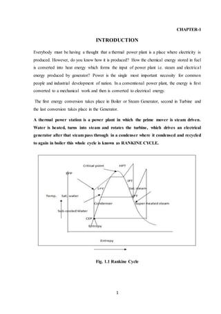
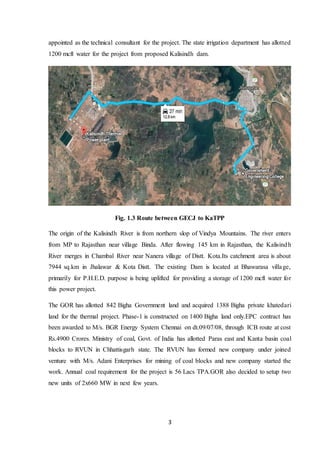
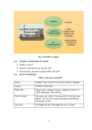
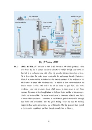
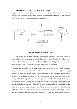
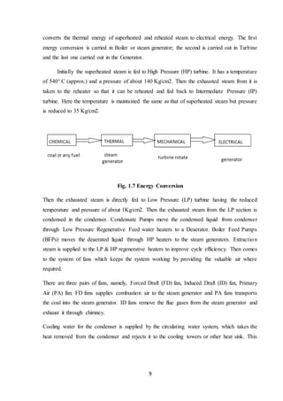
This document provides a summary of Naval Kishor's summer training at the Kalisindh Super Thermal Power Plant (KaTPP) in Jhalawar, Rajasthan. It begins with an introduction to KaTPP, including its location, capacity of 1200MW from 2 units of 600MW each, and annual coal requirements of 56 lakh tonnes. It then describes the basic working of a thermal power plant based on the Rankine cycle, involving converting chemical energy from coal to heat energy in steam, then to mechanical energy via a turbine, and finally electrical energy using a generator. The document covers various sections of KaTPP including the coal handling plant, important plant components like the boiler, turbine,
training report NTPC Muzaffarpur Bihar Dilip kumar
This document provides an industrial training report on the generation system of the National Thermal Power Corporation Ltd. (NTPC). It discusses the key components of a thermal power plant that use the modified Rankine cycle to convert the chemical energy of coal into electrical energy. These include the boiler, turbine, condenser, and other auxiliary components. The report also provides an overview of the processes involved in coal handling, steam generation, power generation using steam turbines, and electricity distribution at NTPC power plants. It aims to provide an understanding of the technical aspects and management of thermal power generation.
KALISINDH THARMAL POWER PLANT report by Neeraj PatidarNeeraj Patidar
This document provides an overview of the Kalisindh Thermal Power Project located in Jhalawar, Rajasthan, India. The 1200 MW project uses coal as its primary fuel and has 2 units, each capable of generating 600 MW of electricity. It obtains water from the Kalisindh dam and uses a Rankine cycle to convert the chemical energy in coal into thermal energy and then electrical energy through the boiler, turbine, and generator.
Ntpc (national thermal power corporation) sipat mechanical vocational trainin...haxxo24
This document is a summer training project report submitted by Dinesh Kumar, a mechanical engineering student, on his vocational training at the National Thermal Power Corporation Sipat power plant in Chhattisgarh, India. The report provides an overview of NTPC Sipat, including its location, installed capacity, use of supercritical technology, and environmental management practices. It also describes the basic Rankine cycle used in thermal power plants, the major sub-systems of a power plant such as the coal handling plant, mills, water treatment plant and boiler, and includes diagrams of a typical power plant layout and the interior of a bowl mill.
The document provides a report on vocational training at the Barh Super Thermal Power Station (BSTPS) in Bihar, India. It discusses the power station's 3,330 MW capacity and describes the process by which coal is transported and converted into electricity. Coal is first unloaded and crushed, then pulverized and blown into boilers to produce steam. The steam powers turbines that generate electricity, which is sent to the grid after increasing the voltage. The report also outlines the power station's layout and components involved in generating, transmitting, and distributing electricity from coal to end users.
This training report provides an overview of the 2x600 MW Kalisindh Thermal Power Project located in Jhalawar, Rajasthan. The report discusses the plant layout and various systems involved in power generation including the coal handling system, raw water and cooling systems, steam generation train, transformers, ash handling plant, switchyard and control room. It also includes the objectives, methodology adopted and conclusions from the training. Single line diagrams and technical specifications of major equipment are provided.
This document provides an overview of the National Thermal Power Plant in Kahalgaon, Bihar, India. It discusses that NTPC Kahalgaon has an installed capacity of 2340 MW and is fueled by coal sourced from nearby mines. The document outlines the key areas and systems within the plant including the coal handling plant, boiler and its auxiliaries, turbine auxiliaries, generator and switchyard. It also provides background on NTPC as the largest power company in India and describes the general layout of a thermal power plant's four main circuits for coal/ash, air/gas, feedwater/steam, and cooling water.
The document is a vocational training report submitted by three electrical engineering students from the University Institute of Technology, Burdwan University after completing an internship at the Farakka Super Thermal Power Station from June 25 to July 24, 2018. It includes an introduction to NTPC, details about the Farakka power plant, an explanation of the process from coal to electricity, and descriptions of the key components and systems within the power plant such as the coal handling plant, 400kV switchyard, boiler and its auxiliaries, turbine components, and electrical equipment.
The document provides details about Sachin Verma's vocational summer training at the NTPC Tanda thermal power plant. It includes acknowledgements, an introduction to NTPC and the Tanda plant, descriptions of the plant's location and features, and explanations of the power generation process using the Rankine cycle and the various systems involved such as the boiler, steam turbine, and electrical equipment. It also outlines the goals and expected benefits of Sachin's training experience at the NTPC Tanda facility.
Nikhil kumar project report ON NTPC KANTINikhil Singh
This document provides an overview of a summer vocational training project completed by Nikhil Kumar at the Kanti Bijlee Utpadan Nigam Limited power plant in Muzaffarpur, Bihar, India from June 16th to July 15th 2013. The 3-page report acknowledges those who supported and guided the training, and declares that the report was submitted to fulfill degree requirements. It also includes an abstract that briefly outlines the key components and processes involved in a coal-fired thermal power plant.
This document is a summer training project report submitted by Emam Raza, a student of mechanical engineering at KIET School of Engineering & Technology. The report details Raza's training at the NTPC Dadri power plant. It includes declarations by Raza, acknowledgements of those who assisted him, and sections on India's power sector, the National Thermal Power Corporation, and details about the NTPC Dadri plant such as its location, capacity, layout, and descriptions of the coal handling plant and mill sub-systems.
This document provides an overview and report on a vocational training project conducted by Tarun Kumar at the Kanti Thermal Power Station. It includes sections on acknowledging those who supported the training, an abstract describing the thermal power generation process, a table of contents, and sections covering topics like the power plant overview, generation process, boiler components, turbines, and control systems. The document aims to provide insight gained from Tarun Kumar's month-long industrial training placement at the thermal power facility.
The document is an internship report submitted by Aditya Aryan about his four-week internship at the National Thermal Power Corporation (NTPC) power plant in Chennai, India. It provides an overview of NTPC, describes the key components and operations of a thermal power plant including the boiler, turbine, generator and cooling towers. It also includes figures and diagrams to illustrate the power plant layout and components. The report aims to document Aditya's experience and learnings during his internship at the NTPC power plant.
kota super thermal Power station training reportEr. Aman Agrawal
it is a practical training report on kota super thermal power station
For any other enquiry u can contact me on +919540278218....
and can join my Page www.facebook.com/engineeringindia
Industrial Training Report on NTPC FaridabadPawan Agrawal
This industrial training report provides an overview of NTPC Faridabad power plant. The report discusses the plant's location, installed capacity, production inputs such as natural gas and naphtha fuels, and key mechanical systems including the gas turbine, waste heat recovery steam generator (WHRSG), and steam turbine. It also describes electrical systems like the switchyard, generator, transformers, and switchgear. In summary, the report details the major components and operations of the combined cycle gas and steam turbine power plant located in Faridabad, Haryana, India.
This document provides an overview of a practical training seminar presented to the CompuCom Institute of Information Technology & Management Jaipur on NTPC Kahalgaon power station. It discusses the history and setup of NTPC as India's largest power company. The summary describes the three step process of generating electricity through: 1) converting coal to steam, 2) using steam to power turbines for mechanical energy, and 3) generating electricity through power stations and distributing it via transmission lines. Key electrical equipment at the power station like alternators and transformers are also outlined.
kalisindh thermal report by hariom nagar hariom nagar
The document provides information about the Kalisindh Thermal Power Project (KaTPP) located in Jhalawar, Rajasthan, India. Some key details:
- The 1200 MW coal-based thermal power project is located 12 km from Jhalawar. Land and water resources have been allotted for the project.
- The plant uses pulverized coal as its primary fuel. Coal is supplied from captive coal blocks allotted in Chhattisgarh and transported via rail.
- The plant employs a Rankine cycle to generate power. Coal is burned to produce high pressure steam which drives turbines connected to generators, producing electricity.
Summer training report on NTPC Badarpur ,DELHI
This Report includes the following department
1. Turbine Maintenance Department
2. Boiler Maintenance Department
3. Plant Auxiliary Maintenance
4. Coal Handling Department
The document is a report on a gas turbine power station submitted as part of an industrial training program. It provides background on the power company and details specifications of various power stations under its operation. It then describes the components, working, and types of gas turbine power plants as well as combined cycle power plants in detail across several chapters.
NTPC was established in 1975 by the Government of India to address growing power demand. It is now the largest power generating company in India with over 30 GW of installed capacity from coal, gas, hydro, and renewable sources. NTPC started with thermal power plants and has expanded into various power generation technologies and business areas. The document provides details on NTPC's thermal power plants across India, including their locations and installed capacities.
This industrial training report summarizes Rajan Kumar Choudhary's internship at the National Thermal Power Corporation plant in Korba, Chhattisgarh, India. It includes declarations of original work, descriptions of the basic processes in coal-fired thermal power generation including combustion of coal to produce steam, expansion of steam in turbines, and the Rankine cycle of heating water to produce pressurized steam. It also provides an overview of the National Thermal Power Corporation as the largest thermal power producer in India, with descriptions of its coal-fired power stations.
The document provides information about Anil Jadon's industrial training at the NTPC power plant in Faridabad. It discusses the company NTPC, describes the Faridabad plant and its 432 MW capacity powered by natural gas. It explains the basic working of the power plant, from burning natural gas in the gas turbine to generating electricity. It also discusses the electrical systems, distribution of electricity, control and instrumentation, advantages of natural gas, and precautions taken at the plant. The training helped clear Anil's concepts and understand how electricity is generated at the large scale, efficient Faridabad plant.
Project report of kota super thermal power plantHîmãńshu Mêęńä
This document provides a summary of a practical training report submitted by Himanshu Derwal at the Kota Super Thermal Power Station from June 1-30, 2013. The report describes the power station's layout and key components including the coal handling plant, ash handling plant, boiler, steam turbine, turbo generator, cooling system, water treatment plant, and control room. It provides technical details and specifications of the various units and aims to document the practical experience and knowledge gained during the training.
National Thermal Power Corporation (NTPC) was established in 1975 to supplement India's efforts in increasing thermal power generation. It has since grown to become the largest power company in India and one of the largest in Asia, with over 34,000 MW of generation capacity across coal and gas plants. NTPC aims to increase capacity to 56,000 MW by 2012 and 75,000 MW by 2017. It has diversified into areas like hydro power, coal mining, oil and gas, power trading and distribution. NTPC's Anta gas power plant began operations in 1990 and generates 419 MW of power for states in northern India. The plant strives for excellence through various quality certifications and corporate social responsibility initiatives in local
Project Report on Industrial Summer Training at NTPC SimhadriAshish Uppu
The following pdf is a Project Report about my Industrial Training at NTPC Limited Simhadri, Visakhapatnam, Andhra Pradesh, India. It includes all the fundamentals of a Thermal Power Plant: its layout, various departments, principal components etc. It also contains a brief profile about the company.
Training Report on Barauni Thermal Power StationGulshan Singh
This document provides details about a training report submitted by Gulshan Kumar Nirala at the Barauni Thermal Power Station in Begusarai, Bihar, India from July 2-31, 2014. It includes an introduction to the power station, which has a total generation capacity of 865 MW across various units commissioned between 1977-2013. It also discusses the site selection criteria for the power station including its location on the banks of the Ganga River near key transportation routes, the land acquired, and planned coal linkage. The report further describes the various systems at the power station including the coal handling plant, ash handling plant, boiler, steam turbine, turbo generator, cooling system, and main control room.
This training report summarizes Pratik Gupta's vocational training at the SIPAT Super Thermal Power Project. It provides details on the production of electricity at a thermal power plant. Coal is ground and blown into boilers where it burns, heating water in tubes to produce high pressure steam. The steam powers turbines connected to generators, producing electricity. The steam is then condensed back into water in condensers to be reused in the cycle. The report outlines the key components and processes involved in electricity generation at a coal-fired thermal power station.
Steam turbines and its associated systems(ntpc ramagundam)abdul mohammad
Steam turbine is an excellent prime mover to convert heat energy of steam to mechanical energy. Of all heat engines and prime movers the steam turbine is nearest to the ideal and it is widely used in power plants and in all industries where power is needed for process.
In power generation mostly steam turbine is used because of its greater thermal efficiency and higher power-to-weight ratio. Because the turbine generates rotary motion, it is particularly suited to be used to drive an electrical generator – about 80% of all electricity generation in the world is by use of steam turbines.
Rotor is the heart of the steam turbine and it affects the efficiency of the steam turbine. In this project we have mainly discussed about the working process of a steam turbine. The thermal efficiency of a steam turbine is much higher than that of a steam engine.
The document provides a training report on the Kalisindh Thermal Power Project in Jhalawar, Rajasthan. It discusses that the power plant has two units that generate 600 MW each for a total output of 1200 MW. It then describes the various processes involved in coal-fired thermal power generation including the coal handling plant, boiler, turbine, generator and other key components. The report also discusses the plant overview, principle of operation, efficiency and concludes with references.
Sagar mehta summer training thermal power station full reportSagar Mehta
This document provides a practical training report submitted by Sagar Mehta to Rajasthan Technical University in partial fulfillment of the requirements for a Bachelor of Technology degree. The report details Mehta's summer training at the Nashik Thermal Power Station in Maharashtra, India. It includes sections on the history of the power sector and thermal power generation in India, an overview of the Nashik Thermal Power Station, descriptions of the key components and operations of a steam power plant, and summaries of Mehta's experiences working in various parts of the plant during the training.
This document provides an industrial training report on the generation system of the National Thermal Power Corporation Ltd. (NTPC). It discusses the key components of a thermal power plant that use the modified Rankine cycle to convert the chemical energy of coal into electrical energy. These include the boiler, turbine, condenser, and other auxiliary components. The report also provides an overview of the processes involved in coal handling, steam generation, power generation using steam turbines, and electricity distribution at NTPC power plants. It aims to provide an understanding of the technical aspects and management of thermal power generation.
training report on thermal power plant & thermal power generation by sagar me...Sagar Mehta
This document provides a practical training report submitted by Sagar Mehta to Rajasthan Technical University in partial fulfillment of the requirements for a Bachelor of Technology degree. The report details Mehta's summer training at the Nashik Thermal Power Station in Maharashtra, India. It includes sections on the history of the power sector and thermal power generation in India, an overview of the Nashik Thermal Power Station, descriptions of the various systems and processes within a thermal power plant including the steam power plant, coal handling plant, water treatment plant, boilers, turbines, generators, condensers and ash handling plant. The report concludes with discussions on energy conservation, auditing, and suggestions.
training reportON Thermal power plantt (nashik tps)pdfSagar Mehta
This document provides a practical training report submitted by Sagar Mehta to Rajasthan Technical University in partial fulfillment of the requirements for a Bachelor of Technology degree. The report details Mehta's summer training at the Nashik Thermal Power Station in Maharashtra, India. It includes sections on the history of the power sector and thermal power generation in India, an overview of the Nashik Thermal Power Station, descriptions of the various systems and processes within a thermal power plant including the steam power plant, coal handling plant, water treatment plant, boilers, turbines, generators, condensers and ash handling plant. The report concludes with discussions on energy conservation, auditing, and suggestions.
The document provides details about a power plant familiarization training carried out at NTPC Ltd Ramagundam Super Thermal Power Station from January 16-31, 2015. It includes an introduction to NTPC, an overview of the energy conversion process at the power plant from coal to steam to electricity, and descriptions of various power plant equipment involved such as coal handling equipment, fans, air preheaters, the boiler and its auxiliaries, the turbine, condenser, heaters, deaerator, boiler feed pump, generator and cooling tower.
The document provides details about Anant Narayan Sharma's 60-day practical training report at the Kota Super Thermal Power Station (KSTPS) in Kota, Rajasthan, which was submitted in partial fulfillment of his Bachelor of Technology degree in Electrical Engineering. It consists of 16 chapters that describe the layout, components, and operations of the KSTPS including the coal handling plant, ash handling plant, electrostatic precipitator, boiler, steam turbine, turbo generator, cooling system, excitation system, water treatment plant, control room, protections, and salient features of the power station. The report aims to provide an understanding of the practical implementation and functioning of a thermal power plant based on the knowledge and
This document is a project report submitted by Sushant Kumar summarizing his one month vocational training at the Kanti Bijlee Utpadan Nigam Limited power plant. The report provides an overview of the plant's operations including the processes of generating electricity from coal, the main boiler and turbine components, and control systems used. It also describes the milling system for pulverizing coal and the light up process for initially igniting the coal furnace.
This document provides an overview of the internship experience of Sagar Chand at Rajghat Power Station from May 5, 2014 to June 9, 2014. It begins with an acknowledgment of those who supported and guided him. It then includes sections on power plant basics, the components and processes involved in thermal power generation including steam, the Rankine cycle, steam turbines, and the various circuits. It also covers control and instrumentation systems used in power plants. The document is intended to provide knowledge gained from the internship that will be valuable for Sagar's career as an electrical engineer.
The document is a training report submitted by Amit Kumar describing his one month training at the Kanti Bijlee Utpadan Nigam Limited power plant in Muzaffarpur, Bihar, India. It provides an overview of the plant, describing that it has two 110MW coal-fired generating units. It then summarizes the key components and processes involved in thermal power generation, including converting coal to steam in the boiler, using steam to power the turbine for mechanical energy, and generating electricity through the generator. It concludes by outlining the sections to be covered in the full report.
This document is an industrial training report submitted by Pawan Agrawal for his Bachelor of Technology degree in Electrical Engineering. The report provides details about Pawan's summer training at the NTPC Faridabad power plant. It begins with an acknowledgment section thanking various NTPC officials who helped with the training. The report then provides information about NTPC as a company, an introduction to the NTPC Faridabad plant including its location, capacity and key features. It describes the basic working of the combined cycle power generation process used at the plant. It also provides details about the fuels used, various mechanical systems including the gas turbine, steam turbine and generator. Other sections cover the switchyard, transformers, DC system, switch
The document is a report on a vocational training completed by Debokti Ghosh at the Titagarh Generating Station of CESC Ltd from July 4-16, 2016. It provides an overview of CESC and the Titagarh Generating Station, describing the basic cycles and processes involved in thermal power generation including the coal handling plant, water treatment plant, and boiler operations. The report acknowledges those who assisted and supported the training.
This document is a summer training report submitted by Awnish Anand, a 3rd year mechanical engineering student at SMIC Hyderabad, after completing a 4-week internship at the National Thermal Power Corporation (NTPC) plant in Barh, Bihar from June 1-31, 2016. The report provides an overview of NTPC, details about the Barh Super Thermal Power Plant where the training took place, and describes the basic steps of electricity generation from coal as observed during the internship. It also includes sections on maintenance departments at the plant and the Rankine cycle of thermal power generation.
This ppt is on summer internship at NTPC Badarpur also known as BTPS. NTPC is India's largest power provider and a Maharatna Company, while Badarpur Plant is a thermal coal fired power plant. It is one of the Asia's oldest one. This ppt highlight's working and utilization of various facilities at plant and the explanation of modified rankine cycle.
Performance Evaluation of Small Hydro Power PlantGirish Gupta
This is a project on the study of small hydro power plant of Khairana, Ramgarh, Uttrakhand which is of the capacity 100 KW. This project is done under Center of Excellence, Technical Educational Quality Improvement Programme - II (COE, TEQIP-II) funded by Ministry of Human Resource and Developement, Government of India
- The document provides an overview of the Mejia Thermal Power Plant located in West Bengal, India.
- It discusses the plant's various mechanical and electrical systems including the coal handling plant, boiler system, steam turbine, generator, and switchyard.
- The summary focuses on key components like the boiler that generates high pressure steam, the steam turbine that converts the steam's energy to rotate the generator and produce electricity, and the switchyard that increases the voltage for transmission.
This document is a summer training report submitted by Lekha Raj Meena, a final year electrical engineering student, after completing a 60 day training program at the Nuclear Power Corporation of India Limited (NPCIL) facility in Rawatbhata, Rajasthan. It provides an overview of NPCIL and the Rajasthan Atomic Power Station, where the student received hands-on experience observing the various systems and equipment used in nuclear power generation, helping to understand concepts studied in textbooks. The report includes sections on nuclear power production processes, India's nuclear power program, the main components of a nuclear power plant, different reactor types, site selection criteria, waste management, safety, and an environmental survey lab.
This document provides a summary report of a 15-day summer training program at a Hindustan Zinc Limited Captive Power Plant. It discusses the key components and processes involved in generating electricity from coal at a thermal power plant, including the boiler, turbine, condenser, and feed pump. The report also provides overviews of the coal handling process, basic instrumentation systems, programmable logic controllers, and concludes with references.
Ntpc (national thermal power corporation) sipat mechanical vocational trainin...haxxo24
This document is a report submitted by Khagesh Kumar Chandra detailing his vocational training project at the NTPC Limited Sipat Super Thermal Power Station from June 21, 2012 to June 18, 2012. The project involved gaining an overview of the power plant including topics like super critical technology, basic power plant equipment and operations, boilers, turbines and their maintenance. Khagesh thanks the guides and HR department for organizing the training program and declares the report contains his original work.
Similar to Training reporton ka tpp by naval kishor (20)
Literature Review Basics and Understanding Reference Management.pptxDr Ramhari Poudyal
Three-day training on academic research focuses on analytical tools at United Technical College, supported by the University Grant Commission, Nepal. 24-26 May 2024
Low power architecture of logic gates using adiabatic techniquesnooriasukmaningtyas
The growing significance of portable systems to limit power consumption in ultra-large-scale-integration chips of very high density, has recently led to rapid and inventive progresses in low-power design. The most effective technique is adiabatic logic circuit design in energy-efficient hardware. This paper presents two adiabatic approaches for the design of low power circuits, modified positive feedback adiabatic logic (modified PFAL) and the other is direct current diode based positive feedback adiabatic logic (DC-DB PFAL). Logic gates are the preliminary components in any digital circuit design. By improving the performance of basic gates, one can improvise the whole system performance. In this paper proposed circuit design of the low power architecture of OR/NOR, AND/NAND, and XOR/XNOR gates are presented using the said approaches and their results are analyzed for powerdissipation, delay, power-delay-product and rise time and compared with the other adiabatic techniques along with the conventional complementary metal oxide semiconductor (CMOS) designs reported in the literature. It has been found that the designs with DC-DB PFAL technique outperform with the percentage improvement of 65% for NOR gate and 7% for NAND gate and 34% for XNOR gate over the modified PFAL techniques at 10 MHz respectively.
CHINA’S GEO-ECONOMIC OUTREACH IN CENTRAL ASIAN COUNTRIES AND FUTURE PROSPECTjpsjournal1
The rivalry between prominent international actors for dominance over Central Asia's hydrocarbon
reserves and the ancient silk trade route, along with China's diplomatic endeavours in the area, has been
referred to as the "New Great Game." This research centres on the power struggle, considering
geopolitical, geostrategic, and geoeconomic variables. Topics including trade, political hegemony, oil
politics, and conventional and nontraditional security are all explored and explained by the researcher.
Using Mackinder's Heartland, Spykman Rimland, and Hegemonic Stability theories, examines China's role
in Central Asia. This study adheres to the empirical epistemological method and has taken care of
objectivity. This study analyze primary and secondary research documents critically to elaborate role of
china’s geo economic outreach in central Asian countries and its future prospect. China is thriving in trade,
pipeline politics, and winning states, according to this study, thanks to important instruments like the
Shanghai Cooperation Organisation and the Belt and Road Economic Initiative. According to this study,
China is seeing significant success in commerce, pipeline politics, and gaining influence on other
governments. This success may be attributed to the effective utilisation of key tools such as the Shanghai
Cooperation Organisation and the Belt and Road Economic Initiative.
International Conference on NLP, Artificial Intelligence, Machine Learning an...gerogepatton
International Conference on NLP, Artificial Intelligence, Machine Learning and Applications (NLAIM 2024) offers a premier global platform for exchanging insights and findings in the theory, methodology, and applications of NLP, Artificial Intelligence, Machine Learning, and their applications. The conference seeks substantial contributions across all key domains of NLP, Artificial Intelligence, Machine Learning, and their practical applications, aiming to foster both theoretical advancements and real-world implementations. With a focus on facilitating collaboration between researchers and practitioners from academia and industry, the conference serves as a nexus for sharing the latest developments in the field.
Harnessing WebAssembly for Real-time Stateless Streaming PipelinesChristina Lin
Traditionally, dealing with real-time data pipelines has involved significant overhead, even for straightforward tasks like data transformation or masking. However, in this talk, we’ll venture into the dynamic realm of WebAssembly (WASM) and discover how it can revolutionize the creation of stateless streaming pipelines within a Kafka (Redpanda) broker. These pipelines are adept at managing low-latency, high-data-volume scenarios.
A review on techniques and modelling methodologies used for checking electrom...nooriasukmaningtyas
The proper function of the integrated circuit (IC) in an inhibiting electromagnetic environment has always been a serious concern throughout the decades of revolution in the world of electronics, from disjunct devices to today’s integrated circuit technology, where billions of transistors are combined on a single chip. The automotive industry and smart vehicles in particular, are confronting design issues such as being prone to electromagnetic interference (EMI). Electronic control devices calculate incorrect outputs because of EMI and sensors give misleading values which can prove fatal in case of automotives. In this paper, the authors have non exhaustively tried to review research work concerned with the investigation of EMI in ICs and prediction of this EMI using various modelling methodologies and measurement setups.
Presentation of IEEE Slovenia CIS (Computational Intelligence Society) Chapte...University of Maribor
Slides from talk presenting:
Aleš Zamuda: Presentation of IEEE Slovenia CIS (Computational Intelligence Society) Chapter and Networking.
Presentation at IcETRAN 2024 session:
"Inter-Society Networking Panel GRSS/MTT-S/CIS
Panel Session: Promoting Connection and Cooperation"
IEEE Slovenia GRSS
IEEE Serbia and Montenegro MTT-S
IEEE Slovenia CIS
11TH INTERNATIONAL CONFERENCE ON ELECTRICAL, ELECTRONIC AND COMPUTING ENGINEERING
3-6 June 2024, Niš, Serbia
Introduction- e - waste – definition - sources of e-waste– hazardous substances in e-waste - effects of e-waste on environment and human health- need for e-waste management– e-waste handling rules - waste minimization techniques for managing e-waste – recycling of e-waste - disposal treatment methods of e- waste – mechanism of extraction of precious metal from leaching solution-global Scenario of E-waste – E-waste in India- case studies.
Embedded machine learning-based road conditions and driving behavior monitoringIJECEIAES
Car accident rates have increased in recent years, resulting in losses in human lives, properties, and other financial costs. An embedded machine learning-based system is developed to address this critical issue. The system can monitor road conditions, detect driving patterns, and identify aggressive driving behaviors. The system is based on neural networks trained on a comprehensive dataset of driving events, driving styles, and road conditions. The system effectively detects potential risks and helps mitigate the frequency and impact of accidents. The primary goal is to ensure the safety of drivers and vehicles. Collecting data involved gathering information on three key road events: normal street and normal drive, speed bumps, circular yellow speed bumps, and three aggressive driving actions: sudden start, sudden stop, and sudden entry. The gathered data is processed and analyzed using a machine learning system designed for limited power and memory devices. The developed system resulted in 91.9% accuracy, 93.6% precision, and 92% recall. The achieved inference time on an Arduino Nano 33 BLE Sense with a 32-bit CPU running at 64 MHz is 34 ms and requires 2.6 kB peak RAM and 139.9 kB program flash memory, making it suitable for resource-constrained embedded systems.
Understanding Inductive Bias in Machine LearningSUTEJAS
This presentation explores the concept of inductive bias in machine learning. It explains how algorithms come with built-in assumptions and preferences that guide the learning process. You'll learn about the different types of inductive bias and how they can impact the performance and generalizability of machine learning models.
The presentation also covers the positive and negative aspects of inductive bias, along with strategies for mitigating potential drawbacks. We'll explore examples of how bias manifests in algorithms like neural networks and decision trees.
By understanding inductive bias, you can gain valuable insights into how machine learning models work and make informed decisions when building and deploying them.
1. A
SEMINAR REPORT
ON
PRACTICAL TRAINING
AT
KALISINDH SUPER THERMAL POWER PLANT
In partial fulfilment for the award of the degree
Of
BACHELOR OF TECHNOLOGY
In
ELECTRICAL ENGINEERING
GOVT ENGINEERING COLLEGE JHALAWAR
SUBMITTED TO: SUBMITTED BY:
Mr Ashish Khandelwal Naval Kishor
Head of Department B. Tech. 4th Year
Department of Electrical Engineering Roll No. 2013UEE033
2. i
ACKNOWLEDGEMENT
I oblige to acknowledge my heartiest gratitude to all honourable people who helped me during
my summer training at KALISINDH THERMAL POWER PROJECT-JHALAWAR,
(RVUNL) RAJASTHAN.
I want to express my thanks to Mr. S. S. Meena (Chief Engineer of KaTPP), S. P. Meena
(Training Co-ordinator) for granting me the permission for doing summer training at this
project and to give their valuable time and kind co-operation.
I also thank a lot to other staff members of RRVUNL, BGR & TCE for their further co-
operation to gain the better knowledge about the excellent power plant project in Distt. –
Jhalawar, Rajasthan.
NAVAL KISHOR
B. Tech 4th Year
Electrical Engineering
3. ii
PREFACE
The rise in civilization is closely related to improvement in transportation and requirement of
energy that is not readily available in large quantities but is also readily transportable. A very
peculiar fact about electrical energy is that neither it is directly available in nature nor it is
finally used in this form, yet it is so widely produced and is the most popular high-grade energy.
The purpose behind this training is to understand the difficult concepts in a better way with
gain of knowledge. Report starts with a brief introduction about KALISINDH SUPER
THERMAL POWER PLANT followed by Lighting Arresters, Bus Bars, Insulators and Circuit
Breakers etc. While writing the report and while I was on my training, I was wondering that
science is ever expanding field and engineers are working hard day and night and makes the
life a gift for us.
4. iii
LIST OF CONTENTS
S. NO. NAME PAGE NO.
CHAPTER-1 INTRODUCTION 1-10
1.1 Contribution of TPP in India
1.2 Introduction to KaTPP
1.3 Energy generated in KaTPP
1.4 Plant Overview
1.5 Principle of Operation
1.6 Thermal plant operation procedure
1.7 Pulverised Coal Fuelled power plant
CHAPTER-2 COAL HANDLING PLANT 11-15
2.1 Introduction
2.1 Stages of CHP
CHAPTER-3 IMPORTANT PARS OF TPP 16-26
3.1 Boiler
3.2 Turbine
3.3 Generator
3.4 Condenser
3.5 Cooling Tower
3.6 Water treatment plant
CHAPTER-4 ESP & AHP SYSTEM 27-32
4.1 ESP System
4.2 AHP System
CHAPTER-5 CONTROL ROOM 33-34
5.1 Control & instrumentation system
CHAPTER-6 SWITCHING & TRANSMISSION SYSTEM 35-45
6.1 INTRODUCTION
6.2 Bus bars
6.3 Isolators
6.4 Insulators
6.5 Protective relays
6.6 Circuit Breakers
6.7 Lightening arresters
6.8 Current transformer
6.9 Potential transformer
6.10 CVT
6.11 Single line diagram
CHAPTER-7 EFFICIENCY 46
7.1 Efficiency
7.2 Cycle efficiency
6. v
LIST OF TABLES
S. NO. TABLE NAME PAGE NO.
1.1 Overview of KaTPP 4-5
2.1 Classification of coal 11
2.2 Wagon tippler 12
2.3 Crusher rating 12
3.1 15KW motor rating at KaTPP 16
3.2 Turbine specification 21
3.3 Generator specification 23
3.4 DG set parameters 24
6.1 Isolator rating 37
6.2 CB parameters 41
6.3 LA Parameters 42
6.4 CVT parameters 44
7. vi
LIST OF FIGURES
S. NO. FIGURE NAME PAGE NO.
1.1 Rankine cycle 1
1.2 Contribution of different power sectors in India 2
1.3 Route between GECJ and KaTPP 3
1.4 KaTPP at a glance 4
1.5 Working of KaTPP 6
1.6 Working by rankine cycle 8
1.7 Energy conversion 9
2.1 Coal handling plant 14
3.1 Water tube boiler 17
3.2 Turbine 20
3.3 Internal structure of turbine 21
3.4 Outview of generator 23
3.5 Cooling tower 25
4.1 ESP unit 30
4.2 Working of AHP 32
4.3 AHP at KaTPP 32
5.1 Control & instrumentation 34
6.1 Switchyard of KaTPP 36
6.2 Basic relay circuit 39
6.3 Buchholz relay 40
6.4 Current transformer 42
6.5 Potential transformer 43
6.6 Single line diagram of KaTPP Switchyard 45
8. 1
CHAPTER-1
INTRODUCTION
Everybody must be having a thought that a thermal power plant is a place where electricity is
produced. However, do you know how it is produced? How the chemical energy stored in fuel
is converted into heat energy which forms the input of power plant i.e. steam and electrical
energy produced by generator? Power is the single most important necessity for common
people and industrial development of nation. In a conventional power plant, the energy is first
converted to a mechanical work and then is converted to electrical energy.
The first energy conversion takes place in Boiler or Steam Generator, second in Turbine and
the last conversion takes place in the Generator.
A thermal power station is a power plant in which the prime mover is steam driven.
Water is heated, turns into steam and rotates the turbine, which drives an electrical
generator after that steam pass through in a condenser where it condensed and recycled
to again in boiler this whole cycle is known as RANKINE CYCLE.
Fig. 1.1 Rankine Cycle
9. 2
1.1) CONTRIBUTATION OF THERMAL POWER PLANT IN INDIA
In India, Thermal Power Plants contribute about 60% of the total electricity produced.
Pie chart shows the electricity production percentage by different sectors-
Fig. 1.2 Contribution of different sectors of power supply in India
1.2) INTRODUCATION OF KaTPP
Kalisindh Super Thermal Power Project is located in Jhalawar, Rajasthan. The project site is
about 12 km from Jhalawar Distt. Headquarter and 13 km from Govt. Engineering College
Jhalawar. Site comprises of five villages viz. Nimoda, Undal, Motipura, Singharia, and Devri.
It is 2 km from state highway no. 19 and 8 km from Ramganj Mandi-Bhopal broad gauge rail
line.
The site selection committee of Central Electricity Authority has visited the Nimoda and its
adjoining villages of Jhalawar Distt. In addition, site was found techno- economical feasible
for setting up of a Power Project. The Govt. of Raj. have included this project in 11th five-year
plan. The estimated revised cost of the project is Rs.9479 Crores. M/s. TCE Bangalore has been
10. 3
appointed as the technical consultant for the project. The state irrigation department has allotted
1200 mcft water for the project from proposed Kalisindh dam.
Fig. 1.3 Route between GECJ to KaTPP
The origin of the Kalisindh River is from northern slop of Vindya Mountains. The river enters
from MP to Rajasthan near village Binda. After flowing 145 km in Rajasthan, the Kalisindh
River merges in Chambal River near Nanera village of Distt. Kota.Its catchment area is about
7944 sq.km in Jhalawar & Kota Distt. The existing Dam is located at Bhawarasa village,
primarily for P.H.E.D. purpose is being uplifted for providing a storage of 1200 mcft water for
this power project.
The GOR has allotted 842 Bigha Government land and acquired 1388 Bigha private khatedari
land for the thermal project. Phase-1 is constructed on 1400 Bigha land only.EPC contract has
been awarded to M/s. BGR Energy System Chennai on dt.09/07/08, through ICB route at cost
Rs.4900 Crores. Ministry of coal, Govt. of India has allotted Paras east and Kanta basin coal
blocks to RVUN in Chhattisgarh state. The RVUN has formed new company under joined
venture with M/s. Adani Enterprises for mining of coal blocks and new company started the
work. Annual coal requirement for the project is 56 Lacs TPA.GOR also decided to setup two
new units of 2x660 MW in next few years.
11. 4
Fig. 1.4 KaTPP at a glance
1.3) ENERGY GENERATED IN KaTPP
Number of units=2
Electricity generated by one unit=600 MW
Total electricity generated by plant=2x600=1200 MW
1.4) PLANT OVERVIEW
Table 1.1 Overview of KaTPP
Project Kalisindh Super Thermal Power Project Jhalawar Rajasthan
Capacity 1200MW (2x600 MW)
Project Site Village-Undel, Motipura, Nimoda, Singhania & Deveri of
Tehsil Jhalarapatan, Distt-Jhalawar
Project Location The project site is about 12 km from NH-12, 2km from state
highway and 8 km from proposed Ramganj Mandi-Bhopal
broad gauge rail line.
Land Area 2230 Bigha/564 Hq. (1400 Bigha/350 Hq. in I stage)
12. 5
Water Source and
quantity
Dam on Kalisindh river and 3400 CuM/Hrs.
Fuel Source Main Fuel-Coal from captive coal blocks (Paras east and kanta
Basin in Chhattisgarh state) Secondary Fuel-FO/HSD
Quantity of fuel (at 80%
PLF)
Coal-56 Lacs TPA FO/HSD-13000-14000 KL/A
Electrostatic Precipator 99.9 % Capacity
Stack Height 275 Mtr
Estimated revised cost Rs.9479 Crores
1.5) PRINCIPLE OF OPERATION
For each process in a vapour power cycle, it is possible to assume a hypothetical or ideal
process which represents the basis intended operation and do not produce any extraneous effect
like heat loss.
1. For steam boiler, this would be a reversible constant pressure heating process of water
to form steam.
2. For turbine, the ideal process would be a reversible adiabatic expansion of steam.
3. For condenser, it would be a reversible constant pressure heat rejection as the steam
condenser until it becomes saturated liquid.
4. For pump, the ideal process would be the reversible adiabatic compression of liquid
ending at the initial pressure.
When all the above four cycles are combined, the cycle achieved is called RANKINE
CYCLE. Hence, the working of a thermal power plant is based upon Rankine Cycle with some
modification.
1.6) THERMAL PLANT OPERATION PROCEDURE
The basic understanding of the modern thermal power station in terms of major systems
involved can be done under three basic heads viz. generating steam from coal, conversion of
thermal energy to mechanical power and generation & load dispatch of electric power.
13. 6
Fig. 1.5 Working of TPP
1.6.1) COAL TO STEAM- The coal is burnt at the rate up to 200 tonnes per hour. From
coal stores, the fuel is carried on convey or belts to bunkers through coal tipper. It
then falls in to coal pulverizing mill, where it is grounded into powder as fine as flour.
Air is drawn into the boiler house by drought fan and passed through Preheaters.
Some air is passed directly to bunker and rest, through primary air fan, to pulverizing
mill where it is mixed with powdered coal. The mixture is then carried to bunker of
furnace where it mixes with rest of the air and burns to great heat. This heats
circulating water and produces steam, which passes to steam drum at very high
pressure. The steam is then heated further in the Super heater and fed to high pressure
cylinder of steam turbine. The spent steam is sent to condenser, where it turns back
to water called condensate. Condensate is sent to lower part of steam drum through
feed heater and economizer. The flue gases leaving boiler are used for heating
purpose in feed heater, economizer, and air Preheater. The flue gases are then passed
to electro-static precipitator and then, through draught fan, to chimney.
14. 7
1.6.2) STEAM TO MECHANICAL POWER- Steam first enters the high-pressure
cylinder of turbine where it passes over a ring of stationary/fixed blades, which acts
as nozzle and directs steam onto a ring of moving blades. Steam passes to the other
cylinders through reheater and the process is repeated repeatedly. This rotates the
turbine shaft up to 3000rpm. At each stage, steam expands, pressure decreases and
velocity increases.
1.6.3) MECHANICAL POWER TO ELECTRICAL POWER- To obtained the
electrical power from mechanical power we connect the shaft to an alternator’s
armature. When the armature is rotated and electric, current is produced in the stator’s
windings. The generated electricity is of order 25,000 volts.
1.6.4) SWITCHING AND TRANSMISSION-The produced electricity is cannot to
transmitted as this state so It is passed to a series of three switches called an isolator,
a circuit-breaker, and another isolator. From circuit breaker, current is taken to bus
bars and then to another circuit breaker with its associated isolator before being fed
to the main Grid. Each generator has its own switching and transmission arrangement.
Three-phase system is used for power transmission.
1.6.5) CONTROL AND INSTRUMENTATION- Control and Instrumentation (C & I)
systems are provided to enable the power station to be operated in a safe and efficient
manner while responding to the demands of the national grid system. These demands
have to be met without violating the safety or operational constraints of the plants.
For example, metallurgical limitations are important as they set limits on the
maximum permissible boiler metal temperature and the chemical constituents of the
Feed water. The control and Instrumentation system provides the means of the manual
and automatic control of plant operating conditions to maintain an adequate margin
from the safety and operational constraints. Monitor these margins and the plant
conditions, and provide immediate indications and permanent records. Draw the
attention of the operator by an alarm system to any unacceptable reduction in the
margins. Shut down the plant if the operating constraints are violated.
15. 8
1.7) PULVERIZED COAL FUELED POWER PLANT
A typical pulverized coal fuelled power plant is based on Rankine Thermodynamic cycle. “A
Rankine cycle is a vapour cycle Furnace that relies on the isentropic expansion of high pressure
gas to produce work”. Let us see a super heat Rankine cycle:
Fig. 1.6 Working by Rankine Cycle
This facility first produces steam in a boiler (steam generator). This steam is used to
rotate turbine, which is connected to a shaft of generator. Hence, electricity is produced here.
The used steam is then condensed in a condenser and the condensed liquid is used again in the
steam generator. This is a simple phenomenon, understood by everybody.
For all this, we need a fuel. As the name suggest here coal is used as fuel. Coal is one of the
cheapest and most preferred fossil fuel used as a key to most of the power plants. Usually
delivered by train from Mines to the Coal Handing Plant (CHP). The CHP unloads this it
become more economical to unload the coal. Then the coal stacked, reclaimed, crushed, and
conveyed it to the storage silos near the steam generator. Then it is fed through the Feeder to
the Pulveriser. Feeder is mainly used to weight the amount of coal going to the Pulveriser per
hour. From the Feeder, the coal is fed to the Pulveriser, which powders it, and then it is carried
to the steam generator using pressurized air. Within the steam generator, the coal is atomized
and burned and the heat energy produced is used for producing steam. Here two types of steam
namely superheated & reheated steam are produced in a cycle. The steam turbine generator
16. 9
converts the thermal energy of superheated and reheated steam to electrical energy. The first
energy conversion is carried in Boiler or steam generator; the second is carried out in Turbine
and the last one carried out in the Generator.
Initially the superheated steam is fed to High Pressure (HP) turbine. It has a temperature
of 540° C (approx.) and a pressure of about 140 Kg/cm2. Then the exhausted steam from it is
taken to the reheater so that it can be reheated and fed back to Intermediate Pressure (IP)
turbine. Here the temperature is maintained the same as that of superheated steam but pressure
is reduced to 35 Kg/cm2.
Fig. 1.7 Energy Conversion
Then the exhausted steam is directly fed to Low Pressure (LP) turbine having the reduced
temperature and pressure of about 1Kg/cm2. Then the exhausted steam from the LP section is
condensed in the condenser. Condensate Pumps move the condensed liquid from condenser
through Low Pressure Regenerative Feed water heaters to a Deaerator. Boiler Feed Pumps
(BFPs) moves the deaerated liquid through HP heaters to the steam generators. Extraction
steam is supplied to the LP & HP regenerative heaters to improve cycle efficiency. Then comes
to the system of fans which keeps the system working by providing the valuable air where
required.
There are three pairs of fans, namely, Forced Draft (FD) fan, Induced Draft (ID) fan, Primary
Air (PA) fan. FD fans supplies combustion air to the steam generator and PA fans transports
the coal into the steam generator. ID fans remove the flue gases from the steam generator and
exhaust it through chimney.
Cooling water for the condenser is supplied by the circulating water system, which takes the
heat removed from the condenser and rejects it to the cooling towers or other heat sink. This
17. 10
all working is controlled from a single place called control room. It enables the operator to
direct the plant operation for reliable and efficient production of electrical energy. This is
achieved by the control system installed by the C & I group. These are DAS (Data Acquisition
System), ACS (Analog Control System), FSSS (Furnace Safeguard Supervisory System), and
other relays governing numerous activities.
Last but not the least is the switching and transmission methods used here. The generated power
cannot be transmitted as such. It is stepped up to 132 KV or 400 KV then passed through a
series of three switches an insulator, a circuit breaker and an isolator. Three-phase system is
used for the power transmission. Each generator has its own switchyard and transmission
arrangement.
18. 11
CHAPTER-2
COAL HANDLING PLANT
2.1) INTRODUCTION
Every thermal power plant is based on steam produced on the expanse of heat
energy produced on combustion of fuel. Coal is categorized as follows depending upon fixed
carbon, volatile matter and moisture content:
Table 2.1 Classification of Coal
S. NO. NAME OF COAL % CARBON
1 Anthracite 86%
2 Bituminous 46 to 86%
3 Lignite 30%
4 Peat 5 to 10%
Coal from mines is transported to CHP in railway wagons. It is unloaded in track
hoppers. Each project requires transportation of large quantity of coal mines to the power
station site. Each project is established near coalmine, which meets the coal requirements for
the span of its entire operational life. For the purpose each plant has Merry Go-Round (MGR)
rail transportation system. The loading operation of the coal rake takes place while it is moving
under the silo at a present speed of 0.8 Km/hr. that the loading time for each wagon is one
minute. For unloading of coal from the wagons, an underground track hopper is provided at
the power station.
The term coal handling plant means to store and to handle the coal, which is transported
by the train, and convey to the bunkers with the help of belt conveyers. Through the bunkers,
coal is transferred to the coal mill and drifted to the furnace. The coal handling plant includes
wagon tippler, conveyer belt, crusher house, stacker & reclaimer, bunkers & coal mill.
COAL SUPPLY IN KaTPP-Ministry of coal, Govt. of India has allotted Paras east and
Kanta basin coal blocks to RVUN in Chhattisgarh state.
2.2) STAGES OF COAL HANDLING PLANT
2.2.1) WAGON TIPPLER-The term Wagon Tippler contains two words WAGON &
TIPPLER. Wagon means the compartment of train, which is just like a container,
which is used to carry the coal from mines to generating stations, & the word Tippler
19. 12
means a machine, which is used to unload the wagon into the hopper. Hopper is just
like a vessel, which is made of concrete, & it is covered with a thick iron net on its
top. Here big size coal pieces are hammered by the labors to dispose it into the hopper.
Table 2.2 Wagon Tippler
Capacity 90 tonnes
Types of Tipplers 1. Weighing type, 2. Non weighing type
Angle of Tip 30 ‘to 35’
Wire Ropes 1. Hoisting Ropes, 2. Counter Weight Ropes
Drive unit Motor 37.3 KW
Operating Cycle 10 wagons/Hour on 1 wagon Tippler
Time consume for one
cycle
6 minutes
2.2.2) FEEDER- It is used to control the supply of crushed coal to the mill depending upon
load condition. It is installed under wagon tippler and hopper. In KaTPP there are
four-unbalanced Motor Vibrating Feeder installed in unit 1st.
2.2.3) CHRUSHER/RING GRANULATOR-In ring granulator the material is fed in to
the crushing chamber and is crushed by the rind hammers with impact and rolling
action across the feed, with concentrated pressure. This cracks the coal producing a
granulator product with a minimum of fines upto 20 mm square.
Table 2.3 Crusher Rating
Capacity 500 Tonnes/hr.
Machine Weight 30 Tonnes(approx.)
Max Feed Rate 500 Tonnes/hr.
Rotor Speed 720 r.p.m.
Motor 550 HP
Volts 606 Kv
Phase 3 Phase motor
20. 13
2.2.4) CONVEYORS-Conveyor belt is used to send the coal from coal storage yard and
used to send crushed coal from store to mill bunkers. The carrying capacity of
conveyors belt is 750 tonnes/hrs. that are installed in KaTPP.
Conveyor belt used in coal handling plant (CHP) are of two types
1. Five ply x1000 mm width with 5 mm rubber top side and 5 mm rubber bottom side.
Total thickness of belt: -17 to 18 mm
Power: -1000 KN/m2
2. Four Ply x1000 mm width with 5mm rubber top side and 5 mm rubber bottom side.
Total thickness of belt: -17mm
Power: -800KN/m2
Cold joints are used in joining the conveyor, conveyor belts run with the help of electric
motor, gearbox, fluid coupling geared coupling are installed at head of all conveyors.
2.2.4.1) PARTS OF CONVEYORS:
1) Flap Gate-it provide under coal transfer chutes for replacements of
crusher/conveyors.
2) Deflector Plate-Deflector plates are installed in the chutes coming on conveyors to
keep the coal direction in the centre of the conveyors.
3) Skirt board and Skirt Rubber-These are provided on tail end chutes to avoid
spillages of coal from Conveyors.
4) Stone Picker-Stone picker pick the stones from the running belt manually.
5) Metal Detector-Electromagnets are provided on conveyors to avoid and to save
crusher parts and entry of iron pieces in crusher. It also stops the entry of iron pieces
in coalbunker to save damage of coal mills.
6) Guide Idlers-These idlers help to train/guide the conveyors.
7) Return Idlers-These idlers carries the conveyors belts in return side.
8) R.T.I (Return Training Idler)-These idlers are provided on return side to guide
the conveyors.
21. 14
9) Impact Idler-These Rubber idlers are provided under chutes through which coal
falls on conveyors.
10) Carrying Idlers-These are installed to run the conveyor.
Fig. 2.1 Coal Handling Plant
2.2.5) BUNKERS-Bunkers are fabricated to store the coal before sending to coal mills.
Coal is fed in the bunkers with the help of tripper trolleys installed at 37 m height for
unit 1st and 2nd.There are 20 bunkers for unit 1st and 2nd.
Capacity of a bunker=500 tonne/bunker.
2.2.6) COAL BUNKERS-These are in process storage used for storing crushed coal from
the handling system. Generally, these are made up of the welded steel plates with
vibrating arrangement of the outlet to avoid chocking of coal; normally there are six-
bunker supply coal to the corresponding mills. These are located on the top of mills
to add gravity feeding of coal.
2.2.7) RECLAIM YARD-After filing the coalbunkers extra coal is taken to reclaim yard
after crushing of coal to storage.
2.2.8) COAL CIRCULATION-Coal is transported from the coalmine with the help of
train. Train wagons are emptied with the help of wagon tipplers and sent to the
crusher for crushing. From coal crusher it goes to the bunker through conveyor belt
22. 15
and from coalbunker, it moves to R.C feeder feeds coal to the coal mill, where the
coal is grinded in to powder form.
23. 16
CHAPTER-3
IMPORTANT PARTS OF THERMAL POWER PLANT
3.1) BOILER
Boiler can simply be defined as the device where any liquid is boiled or Boiler may be
defined as a device that is used to transfer heat energy being produced by burning of fuel to
liquid, generally water, contended in it to cause its vaporization. Boiler, in simple terms, can
be called “Steam Generator”.
In simple way, boiler is a device used for producing steam. There are two types of boiler
(depending upon tube content):
a) Fire tube boiler
b) Water tube boiler
Here, boiler used is of water type. In the boiler, heat energy transfer takes place through tube
walls and drum. The gases lose their heat to water in the boiler or superheated. The escape heat
is used to heat the water through economizer.
ID and FD fans are used to produce artificial draught. The fuel oil is used to ignite the boiler
and pulverized coal is lifted from the coal mills by PA fans.
WATER TUBE BOILER USED IN KaTPP WITH 97M HIGHT.
Various motors used in boiler are of different rating and parameters 32KW, 15KW, 11KW, &
3.3KW.
Parameter in 15KW motor
Table 3.1 15KW Motor Rating of KaTPP
Manufacturing CQ. GEAR BOX LTD.CHINA
Motor rating 15 KW
Speed 970 r.p.m
Rated voltage 416 V
25. 18
Rated current 28.4 A
Impedance voltage 80.0 %
Oil weight 20 Kg
Core winding weight 224 Kg
Total weight 600 Kg
Temp rise 50-55°C
3.1.1) BOILER AUXILIARIES-Efficiency of a system is of most concerned. Thus, it is
very important to maintain a system as efficient as possible. Therefore, Boiler
auxiliaries help in improving boiler’s efficiency. Following are the important
auxiliaries used
ECONOMISER: Its purpose is to preheat feed water before it is introduced into
boiler drum by recovering heat from flue gases leaving the furnace.
SUPER HEATER: It increase the temperature of steam to super-heated region.
REHEATER: It is used for heat addition and increase the temperature of steam
coming from high-pressure turbine to 540°C.
DRAFT FANS: They handle the supply of air and the pressure of furnace.
3.1.2) BOILER MOUNTINGS-These are used for the safe operation of boiler. Some
example of mountings used are water level indicator in drum, furnace temperature
probe, reheat release valve, pressure gauges indicating steam pressure etc.
3.2) TURBINE
Turbine is an m/c in which a shaft is rotated steadily by the impact of reaction of steam
of working substance upon blades of a wheel. It converts the potential energy or heat energy
of the working substance into mechanical energy. When working substance is steam, it is called
‘Steam Turbine’.
In the steam turbine, the pressure of the steam is utilized to overcome external
resistance and the dynamic action of the steam is negligibly small.
Working principle of the steam turbine depends wholly upon the dynamic action of
steam. The steam is caused to fall with pressure in a passage of nozzle, due to this fall
in pressure, a whole amount of heat energy is converted into mechanical energy &
26. 19
steam is set moving with the reactor velocity. The rapidly moving particle of steam
enter the moving part of turbine and here suffers a change in the direction of motion
which gives rise to change of momentum and therefore to a force. This constitutes a
driving force to a turbine.
The passage of them/through the moving part of the turbine commonly called the blade,
may take place in such a manner that the pressure at the outlet sides of the blade is equal to that
of the inlet side. Such a turbine is broadly termed as outlet turbine or Impulse type.
On the other hand, the pressure of the steam at outlet from the moving blade may be less
than that at type inlet side of the blade. The drop of pressure suffered by the steam during its
flow through the moving blades causes a further generation of kinetic energy within the blades
and adds to the propelling force, which is applied to the turbine rotor, such a turbine is broadly
termed as Reaction Turbine.
Here in Kalisindh Thermal Power Project N600-16.7/587/537, Re-Het, Three Casing,
Four Exhaust, Tandem Compound Condenser Type Turbine Used.
The turbine is of tandem compound design with separate High Pressure (HP),
Intermediate Pressure (IP) and Low Pressure (LP) cylinders. The HP turbine is of Single Flow
type while IP and LP turbines are of Double Flow type. The turbine is condensing type with
single reheat. It is engineered on reaction principle with throttle governing. The stages are
arranged in HP, IP AND LP turbines driving alternating current full capacity turbo generator.
The readily designed HP, IP and LP turbines are combined and sized to required power
output, steam parameters and cycle configuration to give most economical turbine set. The
design and constructional feature prove their reliability in service and ensure trouble free
operation over long operating periods and at the same time ensuring high thermal efficiencies.
28. 21
Fig. 3.3 Internal structure of Turbine
Table 3.2 Turbine Specification
Rated output with extraction flow 600 MW
Speed 3000 r.p.m
Main steam throttle flow at HP Inlet 1848.5 TPH
Main steam pressure to HP turbine inlet 167 kg/sq.cm
Main steam temperature. to HP turbine inlet 538°C
Re-heater steam flow at IP inlet 1587.942 TPH
Re-heater steam temperature. at IP inlet 538°C
Steam pressure at LP inlet 35.12 kg/sq.cm
Steam flow at LP inlet 1353.7 TPH
Rotation Direction (view from turbine) anticlock wise
Number of stages 42
29. 22
High pressure turbine-
a) Intermediate pressure
b) Low pressure turbine
c) Governing system
1 governing and 8 pressure
5 pressure stage
28 pressure stage
DEH (digital electro hydraulic)
Inlet steam flow governing type Nozzle+throttle
Rated exhaust pressure 0.09 kg/sq.cm
Type of bearing turbine 6 journal +1 thrust
Turbine allowable frequency 47.5 to 51.5 Hz
Turning gear rotation speed 1.5 r.p.m
Ist critical speed of HP & LP rotor 1722 r.p.m
Ist critical speed of LP-A rotor 1839 r.p.m
Ist critical speed of LP-B rotor 1903 r.p.m
Heat regenerative extraction system
3 HP heater +1 Deaerator +4 LP
heater
Final feed water temperature 274.9°C
Maximum bearing vibration 0.076 m
Maximum allowable exhaust temperature. 80°C
Cooling water design flow at condenser 70200 TPH
3.3) GENERATOR
Generator is the important part of thermal power plant. It is a device, which converts
the mechanical energy into electrical energy. Generator is driven by coupled steam turbine at
a speed of 3000 r.p.m. Due to rotation at high speed it gets heated. Therefore, there is cooling
construction enclosing the winding core of the generator. Therefore, during the operation is
being in normal temperature.
In KaTPP, each of the 2 units have been provided with 3-phase turbo generator rated
output 706MVA, 18.525KA, 22KV, 0.85 lagging p.f., 984 rpm and 50 cycles/sec. The
generator has closed loop of hydrogen gas system for cooling of the stator and rotor at a
pressure of 4.5kg/sq.-cm (g).
30. 23
Fig. 3.4 Out view of Generator
Table 3.3 Generator Specification
Made By CQ. GEAR BOX LTD. CHINA
Type QFSN
Apparent output 706 MVA
Active output 600 MW
Power factor 0.85 lagging
Rated voltage 22 KV
Rated current 18525 Amp
Rated speed 3000 r.p.m
Frequency 50 Hz
Phase connections Double gen. star
Cooling mode H20-H2-H2
Rated H2 pressure 4.5 Kg/sq.-cm
Terminal in generator 6
31. 24
3.3.1) DIESEL GENERATOR SET
It is used to emergency purpose to supply auxiliary system of power plant.3 Set Diesel
generator are use in which one is standby.
Table 3.4 DG Set Parameters
Made BY STAMFOARD MAHARASTRA INDIA
Rating 1900 KVA
Speed 1500 R.P.M
Rated Current 2643.37 A
Rated Temp 40°C
AMPS 3.6 A
3.4) CONDENSER
In condenser, the water passes through various tubes and steam passes through a chamber
containing a large number of water tubes (about 20000).
The steam is converted into water droplets, when steam meets water tubes. The
condensate is used again in boiler as it is dematerialized water and 5-6 heats the water, which
was in tubes, during the process of condensation. This water is sent to cooling tower.
Condenser is installed below the LP exhaust. The condenser is of surface type made of
fabricated construction in single shell. The tube is of divided type double pass arrangement,
having two independent cooling water inlet, outlet and reverse and water boxes. This
arrangement facilitates the operation of one-half of condenser when the other half is under
maintenance. The condenser is provided with integral air-cooling zone at the centre from where
air and non-condensable gases are continuously drawn out with the help of mechanical vacuum
pump.
Area of condenser = 9655 sq. m
Cooling water flow rate = 2400 cubic m/Hr.
3.5) COOLING TOWER
It is a structure of height 202 m (tallest in the world) designed to cool the water (coming
from condenser) by natural draught. The cross sectional area is less at the centre just to create
32. 25
low pressure so that ate air can lift up due to natural draught and can carry heat from spherical
drops. The upper portion is also diverging for increasing the efficiency of cooling tower. Hence,
it is named as natural draught cooling tower.
In KaTPP two natural draught cooling towers (2 NDCT) is present with height 202 m each
for each unit.
Fig. 3.5 Cooling Tower
3.6) WATER TREATMENT PLANT
As everyone, know that the cost of any thermal power plant is cores of rupees. So major
problem of any thermal power plant is that how to prevent the corrosion. The water available
cannot be used in boilers as such. The objective of water treatment plant is to produce the boiler
feed water so that there shall be.
33. 26
No scale formation ·
No corrosion ·
No priming or forming problems
Water used in thermal power plant is called ‘Dematerialized Water’ or DM Water.
34. 27
CHAPTER-4
ESP AND AHP SYSTEM
4.1) ELECTROSTATIC PRECIPITATOR (ESP)
Electrostatic Precipitator (ESP) is equipment, which utilizes an intense electric force to
separate the suspended particle from the gases. In India, coal is widely used to generate power.
The exhaust gases are emitted directly into the atmosphere; it will cause great environmental
problems. Therefore, it is necessary to extract this dust and smoke before emitted the exhaust
gases into atmosphere. There are various methods of extracting dust but electrostatic
precipitator is the most widely used. It involves electric changing of suspended particle,
collection of charge particles and removal of charge particles from collecting electrode. Its
various other advantages are as follows:
It has high efficiency i.e. about 99%
Ability to treat large volume of gases at high temperature
Ability to cope with the corrosive atmosphere.
It offers low resistance to the flow of gases.
It requires less maintenance.
4.1.1) WORKING PRINCIPLE- The electrostatic precipitator utilizes electrostatic forces
to separate dust particles from the gases to be cleaned. The gas is passed through a
chamber, which contains steel plates (vertical) curtains. Theses steel curtains divide
the chamber into number of parallel paths. The framework is held in place by four
insulators, which insulate it electrically from all parts, which are grounded. A high
voltage direct current is connected between the framework and the ground, thereby
creating strong electric field between the wires in the framework curtains.
Strong electric field develops near the surface of the wire creates Corona Discharge
along the wire. Thus ionized gas produces +ve and –ve ions. In the chamber plates are
positively charged whereas the wire is negatively charged. Positive ions are attracted towards
the wire whereas the negative ions are attracted towards the plates. On their way towards the
curtains, negative ions strike the dust particle and make them negatively charged. Thus is
collected on the steel curtains.
The whole process is divided into the following parts:
35. 28
Corona Generation
Particle Charging
Particle Collection
Particle Removal
Details of the following are given below-
Corona Generation- Corona is a gas discharge phenomenon associated with the
ionization of gas molecules by electron collision in regions of high electric field
strength. This process requires non-uniform electric field, which is obtained by the use
of small diameter wire as one electrode and a plate or cylinder as the other electrode.
The corona process is initiated by the presence of electron in strong electric field near
the wire. In this region of corona discharge, there are free electrons and positive ions.
Both positive and negative coronas are used in industrial gas cleaning.
In case of negative corona, positive ions generated are attracted towards the negative
electrode or wire electrons towards collecting plates. On impact of negative and serve
as principle means of charging dust.
Particle Charging- These are two physical mechanisms by which gas ions impact
charge to dust particles in the ESP. Particles in an electric fields causes localized
distortion in an electric filed so that electric field lines intersect with the particles of
maximum voltage gradient, which is along electric field lines. Thus, ions will be
intercepted by the dust particles resulting in a net charge flow to the dust particles. The
ions will be held to the dust particles by an induced image charge force between the ion
and dust particle and become charged to a value sufficient to divert the electric field
lines from particles such that they do not intercept.
o Particle Collection- The forces acting on the charged particles are
Gravitational, Inertial, Electrostatic and Aerodynamically. The flow of gas
stream is turbulent flow because it causes the particles to flow in random path
through ESP. Particles will be collected at boundary layers of collector pates.
However, if flow is laminar, charge will act on particles in the direction of
collecting electrode. This force is opposite to viscous drag force and thus in the
short time, particle would achieve Terminal (Migration) velocity at which
36. 29
electrical; and viscous forces are equal. Thus the flow of the charged particle is
decided by the vector sum of these forces i.e. Turbulent.
Particle Removal- In dry removal of dust collected on plates, Rapping Mechanism is
used. It considers of a geared motor, which moves along shaft paced near the support
collector electrode and is provided with cylindrical hammer. On rotating of shaft these
hammers, strike the supports causes’ plate to vibrate and dust is removed from plates.
Removed dust is collected in the Hoppers below the precipitator. At the time of starting
of precipitation of dust from flue gases, the hoppers are at normal temperature but the
ash collected is very hot. So there is a chance of ash deposit at the exit of the hopper
thus causing problem of removing the ash. To avoid this, heaters are provided which
increase the temperature at the exit point of the hopper thus avoiding any undue
accumulation of ash at starting. In other method, the water is allowed to flow down the
collector electrode and hence dust is collected in hoppers below.
4.1.2) GENERAL DESCRIPTION-
The whole ESP is divided into two parts-
Mechanical System
Electrical System
Here we will discuss only Mechanical System (i.e. Precipitator Casing, Emitting and
Collecting System and Hopper).
Precipitator Casing-Precipitator Casing is made of 6mm mild steel plates with
required stiffness. The precipitator casing is all welded construction comprising of pre-
fabricated walls and proof-panels. The roof carries the precipitator internals, insulator
housing, transformer etc. Both emitting and collecting systems are hung from the top
of the casing.
Emitting and Collecting System- Emitting System is the most important part of ESP.
Emitting system consists of rigid emitting frame suspended from four points on the top
of rigid emitting electrodes in the form of open spiral. The four suspension points are
supported on support insulators to give electrical insulation to the emitting frame. The
frame is designed to take up the retention forces of the emitting electrode. The emitting
electrode consists of hard drawn spiral wires and are fastened with hooks to the
discharge frame.
37. 30
Collecting system mainly consists of collecting suspension frame, collection electrodes
and shock bars. Collecting electrode are made of 1.6 mm thick Mild Steel sheets formed
in ‘G’ Profile of 400mm width. Hook and guide are welded on one end and shock iron
on the dipped in rust preventive oil tank. Collecting electrodes bundles are properly
bundled in order to avoid any damage to electrode.
Hoppers- Hoppers are seized to hold the ash for 8-hour collection and is provided under
the casing of ESP. It is of Pyramidal Shape and is 56 in number. It is preferred to
evacuate the hoppers at the earliest as long storage of dust in hopper leads to clogging
of hopper. Also at the bottom of hopper, electrical heating is provided to avoid any
condensation, which could also lead to clogging of hopper. Baffle plates are provided
in each hopper to avoid gas leakage.
Fig. 4.1 Electrostatic Precipitation Unit
4.1.3) RAPPING MECAHISM FOR COLLECTING SYSTEM- During electrostatic
precipitation a fraction of dust will be collected on the discharge on the discharge
electrodes and the corona will be suppressed as the dust layer grows. So rapping is
done in order to remove this dust by hammering the electrodes.
38. 31
As the shaft rotates, the hammer tumbles on to the shock bar that transmits the blow to the
electrode. The completely rapping mechanism is mounted on a single shaft, which is collection
of ash on the collecting electrode.
4.2) ASH HANDLING PLANT (AHP)
ESP collects the ash produced on the combustion of coal. This ash is now required to
dispose off. Ash Handling Plant (AHP) solves this purpose of ash disposal. There are two types
of ash handling process undertaken by AHP.
Dry Ash System
Ash Slurry System
4.2.1) DRY ASH SYSTEM- Dry ash is required in cement factories as it can be directly
added to cement. Hence, the dry ash collected in the ESP hopper is directly disposed
to silos using pressure pumps. The dry ash from these silos is transported to the
required destination.
4.2.2) ASH SLURRY SYSTEM- Ash from boiler is transported to ash dump areas by
means of sluicing type hydraulic system, which consists of two types of system-
Bottom Ash System
Ash Water System
BOTTOM ASH SYSTEM- In this system, the ash slag discharged from the furnace is
collected in water-impounded scraper installed below bottom ash hopper. The ash
collected is transported to clinkers by chain conveyors. The clinker grinders churn ash,
which is then mixed with water to form slurry.
ASH WATER SYSTEM-In this system, the ash collected in ESP hopper is passed to
flushing system. Here low pressure water is applied through nozzle directing
tangentially to the section of pipe to create turbulence and proper mixing of ash with
water to form slurry. Slurry formed in above processes is transported to ash slurry sump.
Here extra water is added to slurry if required and then is pumped to the dump area.
4.2.3) FLY ASH SYSTEM-Even though ESP is very efficient, there is still some ash, about
0.2%, left in flue gases. It is disposed to the atmosphere along with flue gases through
chimney.
39. 32
Fig. 4.2 Working of Ash Handling Plant
Fig. 4.3 Ash Handling Plant at KaTPP
40. 33
CHAPTER-5
CONTROL ROOM
5.1) CONTROL AND INSTRUMENTATION SYSTEM
Control and Instrumentation (C & I) systems are provided to enable the power station to
be operated in a safe and efficient manner while responding to the demands of the national grid
system. These demands have to be met without violating the safety or operational constraints
of the plants.
For example, metallurgical limitations are important as they set limits on the maximum
permissible boiler metal temperature and the chemical constituents of the Feed water. The
control and Instrumentation system provides the means of the manual and automatic control of
plant operating conditions to maintain an adequate margin from the safety and operational
constraints. Monitor these margins and the plant conditions, and provide immediate indications
and permanent records. Draw the attention of the operator by an alarm system to any
unacceptable reduction in the margins. Shut down the plant if the operating constraints are
violated.
Most of the power plant operational controls are automatic. However, at times, manual
intervention may be required. Thus, the plant is provided with monitors and alarm systems that
alert the plant operators when certain operating parameters are seriously deviating from their
normal range.
.
42. 35
CHAPTER-6
SWITCHING AND TRANSMISSION
6.1) INTRODUCTION
The electricity is usually produced in the stator winding of the large modern generators
at about 22,000 volts and is fed through terminal connections to one side of a generator
transformer that steps up the voltage 132000, 220000 or 400000 volts. From here conductors
carry it to a series of three switches comprising an insulator, a circuit breaker and another
isolator.
The circuit breaker, which is a heavy-duty switch capable of operating in a fraction of a
second, is used to switch off the current flowing to the transmission lines. Once the current has
been interrupted, the isolators can be opened. These isolate the circuit breaker from all outside
electrical sources.
From the circuit breaker, the current is taken to the bus bars-conductors, which run the length
of the switching compound and then to another circuit breaker with its associated isolates
before feeding to the grid.
Three wires are used in a ‘three=phase’ system for large power transmission. The centre of the
power station is the control room. Here engineers monitor the output of electricity, supervising
and controlling the operation of the generation plant and high voltage switchgear and directing
power to the grid system as required.
6.2) BUS BARS
Bus Bars are the common electrical component through which a large no. of feeders
operating at same voltage have to be connected.
If the bus bars are of rigid type (Aluminium types), the structure heights are low and
minimum clearance is required. While in case of strain type of bus bars suitable ACSR
conductors are strung / tensioned by tension insulator discs according to system voltages. In
the widely used strain type bus bars, stringing tension is about 500 - 900 kg depending upon
the size of conductor used.
43. 36
Fig. 6.1 Switchyard of KaTPP
6.2.1) BUS BAR ARRANGEMENT MAY BE OF FOLLOWING TYPES, WHICH
ARE BEING USED IN KaTPP
1.) Single bus bar arrangement.
2.) Double bus bar arrangement.
a) Main bus with transformer bus.
b.) Main bus-I with Main bus-II.
3.) Double bus bar arrangement with auxiliary bus.
6.3) ISOLATORS
Isolators which are also called disconnect switches or air break switches after the
assembly as per drawings on the leveled structures the adjustment of connecting pipes, moving
and fixed contacts is done so that all the three phase of the isolator close and open
simultaneously and there is a full surface contact between moving and fixed contacts. Such
switches are generally used on both sides of equipment in order that repairs and replacement
44. 37
of the equipment can be made without any danger. They should never be opened until the
equipment in the same circuit has been turned off and should always be closed before the
equipment is turned on.
The adjustment of the tendon pipes levelling of post insulator, stop holts in the fixed contacts
etc. is done for smooth operation of insulator. Following type of insulator are being used in
KaTPP-
a) Isolator without earth blades.
b) Isolator with earth blade.
c) Tendon isolator.
Table 6.1 Isolator Ratings
Type VB
Manufacturing by GR-power switchgear ltd Hyderabad
Rated voltage 420/245 KV
Rating 400/200A
Impulse voltage 1050KVp
Total weight 1300/950kg
Short time current 40KA for 3 sec
Control voltage 220V DC
6.4) INSULATORS
The insulators for the overhead lines provide insulation to the power conductors from
the ground so that currents from conductors do not flow to earth through supports. The
insulators are connected to the cross arm of supporting structure and the power conductors
passes through the clamp of the insulator. The insulators provide necessary insulation between
line conductors and supports and thus prevent any leakage current from conductors to earth. In
general, the insulators should have the following desirable properties:
45. 38
1 High mechanical strength in order to withstand conductor load, wind load etc.
2 High electrical resistance of insulator material in order to avoid leakage currents to earth.
3 High relative permittivity of insulator material in order that dielectric strength is high.
4 The insulator material should be non-porous; free from impurities and cracks otherwise the
permittivity will be lowered.
5 High ratio of puncture strength to flash over.
6.4.1) TYPE OF INSULATORS
There are three types of insulators used for overhead lines:
Pin Type
Strain Type
Suspension Type
6.5) PROTECTIVE RELAYS
A Protective relay is a device that detects the fault and initiates the operation of the circuit
breaker to isolate the defective element from the rest of the system.
The relays detect the abnormal condition in the electrical circuits by constantly measuring the
electrical quantities i.e. voltage, current, frequency, phase angle which are different under
normal and fault conditions. Having detected the fault, the relay operates to close the trip circuit
of the breaker, which results in opening of the breaker and disconnection of the faulty circuit.
Relay circuit connections can be divided in three parts:
1.) Primary winding of a C.T. that is connected in series with the line to be protected.
2.) Secondary winding of C.T. and the relay operating coil.
3.) Third part is the tripping circuit, which may be either a.c. or d.c... It consists of a source of
a supply, the trip coil of a circuit breaker and the relays stationary contacts.
When a short circuit occurs at point F on the transmission line the current increases to enormous
value. This results in a heavy current flow through the relay coil, causing the relay to operate
by closing its contacts. This in turn closes the trip circuit of the breaker, making the C.B. open
and isolating the family section from the rest of the system. In this way, the relay ensures the
safety of the circuit equipment from damage and normal working of the healthy portion of the
system.
46. 39
Fig. 6.2 Basic Relay Circuit
Basic qualities that a protective relay must possess are:
1.) Selectivity
2.) Speed
3.) Sensitivity
4.) Reliability
5.) Simplicity
6.) Economy
6.5.1) BUCHHOLZ RELAY
It is a gas-actuated relay installed in oil-immersed transformers for protection against
all kinds of faults. It is used to give an alarm in case of incipient (i.e. slow developing) faults
in the transformer and to disconnect the transformer from the supply in the event of severe
47. 40
internal faults. It is usually installed in the pipe connecting the conservator to the main tank. It
is a universal practice to use BUCHHOLZ relay on all such oil-immersed transformers having
ratings in excess of 750kVA.
Fig. 6.3 Buchholz Relay
6.6) CIRCUIT BREAKER
Circuit breakers are used for switching & protection of various parts of power
system. Circuit breaker is a piece of equipment, which can
1) Make or break a circuit manually or automatically under normal condition.
2) Break a circuit automatically under fault condition.
3) Make a circuit either manually or by remote control under fault conditions.
6.6.1) CLASSIFICATION OF CIRCUIT BREAKERS
They are generally classified based on the medium used for arc elimination
(i) Oil circuit breakers, which employ some insulating oil for arc extinction.
(ii) Air-blast circuit breakers in which high-pressure air blast is used for extinguishing the arc.
(iii) Sulphur hexa fluoride C.B. in which SF6 gas is used for arc extinction.
(iv) Vacuum C.B. in which vacuum is used for arc extinction.
Here in KaTPP 3AP1FI/3AP2FI type CB are used for 400KV &220KV Switchyard.
48. 41
Table 6.2 Parameter of CB
Parameters 400KV yard For 220KV yard
Type 3AP2FI 3AP1FI
Rated voltage 420KV 245KV
Rated lighting impulse
withstand voltage
1425KVp 1050KVp
Rated power frequency
withstand voltage
610KV 460KV
Frequency 50Hz 50Hz
Rated nominal current 3150A 3150A
Rated short circuit breaking
current
50KA 40KA
Rated short circuit time
duration
3 sec 3 sec
Rated out of phase breaking
current
12.5A 10KA
First pole to clear factor 1.3 1.3
Rated single capacitor bank
break current
400A 125A
Rated line charging break
current
600A 400A
DC component 46% 25%
Rated operation sequence o-.3s-co- 0-.3S-CO-3M-CO
Weight of SF6 6.0 bar rel 6.0bar rel
49. 42
Total weight 39kg 22kg
Control voltage 5400kg 3000kg
Operation
mechanism/heating voltage
220V DC
240V AC
220V DC
240V AC
6.7) LIGHTENING ARRESTORS
An electric discharge between cloud and earth, between clouds or between the charge
of the same cloud is known is as Lightening.
A Lightening Arrester or a surge diverter is a protective device, which conducts the high
voltage surges on the power system to the ground.
Table 6.3 Parameters of LA
Type A
Maximum Voltage 245KV
MAX Current 2000A
RELAY Maximum Current 40A
Rating 165KW
Total weight 215kg
6.8) CURRENT TRANSFORMER
Fig. 6.4 Current Transformer
50. 43
Current transformer is used for monitoring the current for the purpose of measuring and
protection. The dead tank current transformer accommodate the secondary cores inside the
tank, which is at ground potential. CT used current ratio 1000:1 and range is 1A-5A.CT
connected in series while PT in parallel.
6.9) POTENTIAL TRANSFORMER
These transformers are extremely accurate ratio step down transformers and are used
in conjunction with standard low range voltmeter (usually 150 volt) whose deflection when
divided by voltage transformation ratio, gives the true voltage on the high voltage side. In
general, they are of the shell type and do not differ much from the ordinary two winding
transformer, except that their power rating is extremely small.
Fig. 6.5 Potential Transformer
Up to voltage of 5000 potential transformers are usually of dry type, between 5000 and 13800
volts, they may be either dry type or oil immersed type, although for voltage above 13800 they
are oil type. Since their secondary windings are required to operate instruments, relays or pilot
lights, their ratings are usually 42 to 100 watts.
6.10) CAPACITIVE VOLTAGE TRANSFORMER
Capacitive voltage transformers are special kind of power transformers using
capacitors to step down the voltage.
51. 44
APPLICATION
1. Capacitive voltage transformers can be effectively as potential sources for measuring,
metering, protection, carrier communication and other vital functions of an electrical
network.
2. CVT are constructed in single or multi-unit porcelain housing with their associated
magnetic units. For EHV system cuts are always supplied in multi-unit construction.
3. In case of EHV cuts, the multi-unit system has many advantage easy to transport and
storing, convenience in handling.
Table 6.4 CVT Specification
Type 10SK-245/460/1050
Rated voltage 245KV
Frequency 50Hz
Current 40KA for 3 sec
Rated primary current 2000A
Continues current 2400A
Insulation class A
Secondary terminal rating 2A
Oil weight 210kg
Total weight 850 kg
6.11) SINGLE LINE DIAGRAM
53. 46
CHAPTER-7
EFFICIENCY
7.1) EFFICIENCY
Efficiency is defined as the ratio of output to input. Efficiency of any thermal power
plant can be divided into four parts-
1) Cycle Efficiency
2) Boiler Efficiency
3) Generator Efficiency
4) Turbine Efficiency
Efficiency of thermal power plant is defined as in the term of overall efficiency i.e.
Overall efficiency = cycle × boiler × generator × turbine efficiency
7.2) CYCLE EFFICIENCY- Cycle efficiency is defined as the ration of energy available
for conversion in work to the heat supplied to the boiler.
7.3) BOILER EFFICIENCY- Efficiency of boiler depends upon the following factors:
a) Dry flue gas loss: Increase by excess air in boiler.
b) Wet flue gas loss: Moisture in coal.
c) Moisture in combustion loss: Hydrogen loss.
7.4) GENERATOR EFFICIENCY- Efficiency of generator is about 98% also its
efficiency depends upon:
a) Copper and iron loss
b) Windage losses
7.5) TURBINE EFFICIENCY-It means the efficiency of steam turbine in converting the
heat energy made available in the cycle into actual mechanical work.
54. 47
CONCLUSION
This is my first practical training in which I learned lot of things and seen lot of huge
machine like Turbine, Boiler, Generator, cooling tower and many other things.
The architecture of the power plant, the way various units are linked and the way
working of whole plant is controlled make the student realize that engineering is not just
learning the structure description and working of various machine but the great part is of
planning proper and management.
I think training has essential for any student. It has allowed an opportunity to get an
exposure of the practical implementation to theoretical fundamentals.