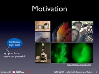
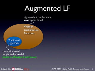
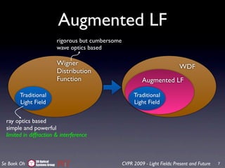
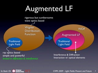
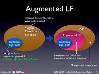
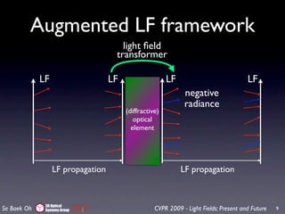
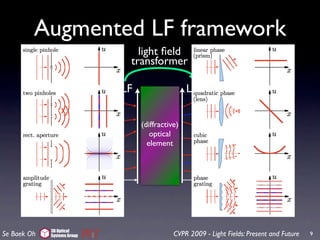
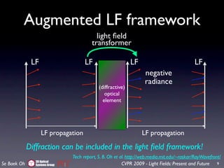
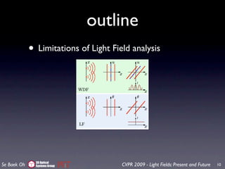
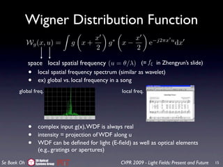
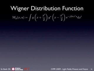
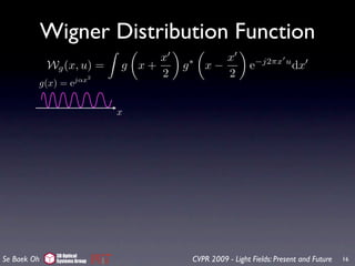
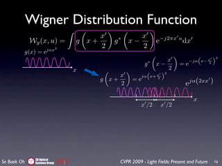
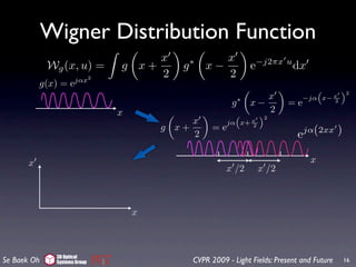
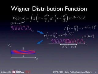
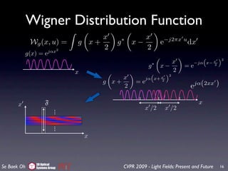
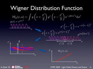
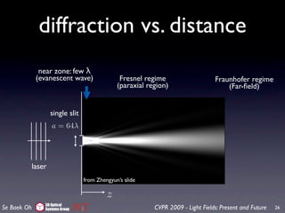
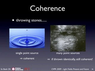
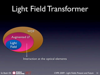
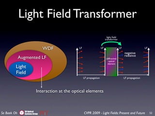
The document summarizes a presentation on light fields and the Wigner distribution function. It begins with introducing traditional light fields and their limitations in modeling diffraction and interference effects. It then describes how augmenting light fields can address these limitations by incorporating wave optics concepts like the Wigner distribution function. The presentation provides examples of how augmented light fields can model interference patterns from experiments like Young's double slit experiment. It concludes by discussing properties of the Wigner distribution function and how it relates to modeling light fields.

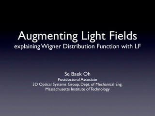

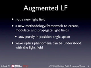
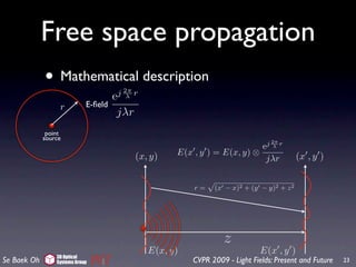
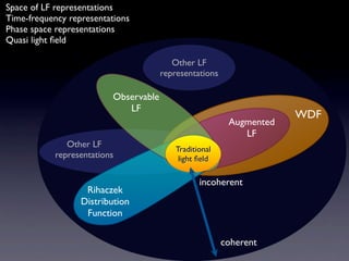
![Free space propagation
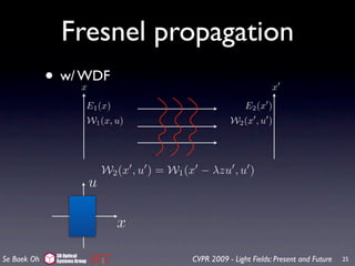
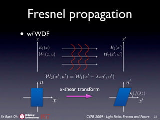
• with the paraxial approximation
spherical
wavefront 1
quadratic (x − x)2 + (y − y)2 + z2 ≈z+ (x − x)2 + (y − y)2
wavefront 2z
z
point
source
exp j 2π
λ (x − x)2 + (y − y)2 + z 2
E(x , y ) = E(x, y) dxdy
jλ (x − x)2 + (y − y)2 + z 2
j 2π z
e λ π
≈ E(x, y) exp j [(x − x)2 + (y − y)2 ] dxdy
jλz λz
Fresnel diffraction formula
3D Optical
Se Baek Oh Systems Group CVPR 2009 - Light Fields: Present and Future 24](https://image.slidesharecdn.com/alfwdf-090708133459-phpapp01/85/Augmenting-Light-Field-53-320.jpg)
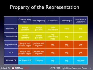
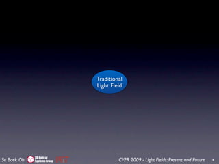
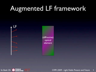
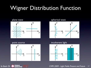
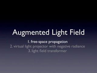
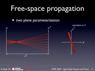
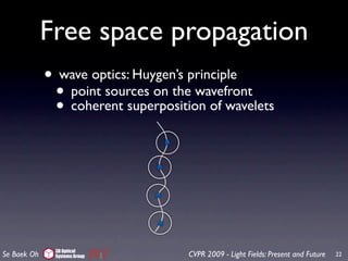
![Free space propagation
• with the paraxial approximation
spherical
wavefront 1
quadratic (x − x)2 + (y − y)2 + z2 ≈z+ (x − x)2 + (y − y)2
wavefront 2z
source & aperture size << z
z
point
source
exp j 2π
λ (x − x)2 + (y − y)2 + z 2
E(x , y ) = E(x, y) dxdy
jλ (x − x)2 + (y − y)2 + z 2
j 2π z
e λ π
≈ E(x, y) exp j [(x − x)2 + (y − y)2 ] dxdy
jλz λz
Fresnel diffraction formula
3D Optical
Se Baek Oh Systems Group CVPR 2009 - Light Fields: Present and Future 24](https://image.slidesharecdn.com/alfwdf-090708133459-phpapp01/85/Augmenting-Light-Field-54-320.jpg)
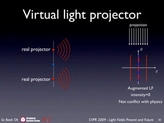
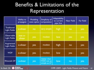
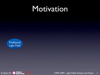
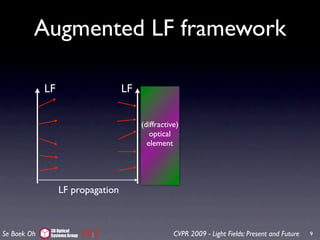
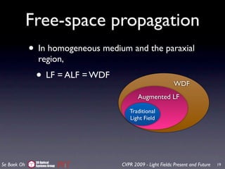
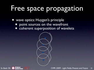
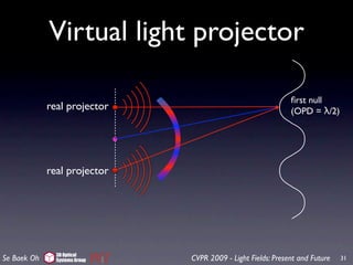
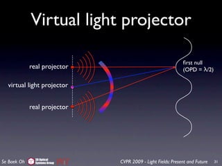
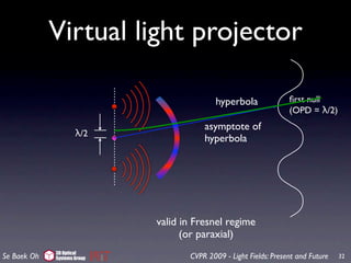
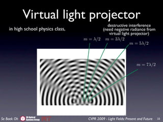
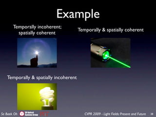
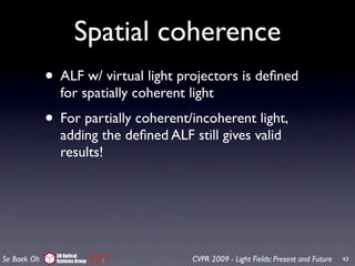
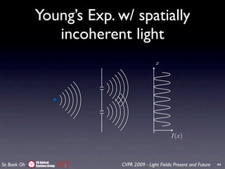
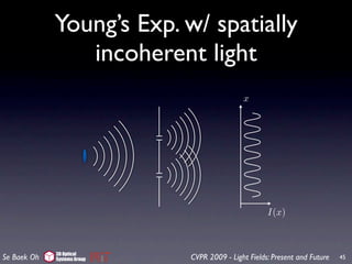
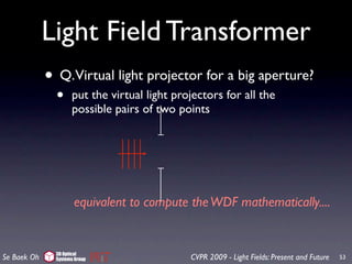
![Virtual light projector
projection
2π
real projector cos
λ
[a − b]θ θ
negative
virtual light projector positive
at the mid point
x
real projector
Augmented LF
intensity=0
Not conflict with physics
3D Optical
Se Baek Oh Systems Group CVPR 2009 - Light Fields: Present and Future 30](https://image.slidesharecdn.com/alfwdf-090708133459-phpapp01/85/Augmenting-Light-Field-70-320.jpg)
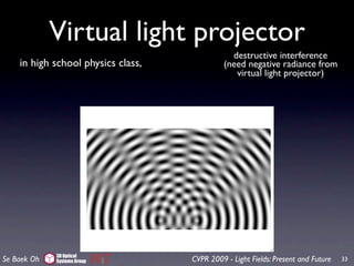
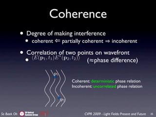
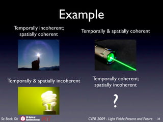
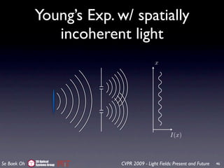


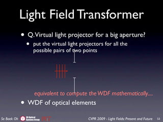
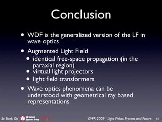
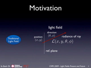
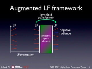
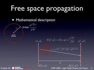
![er of times with
ference terms are
tood with the in-
the two pinholes
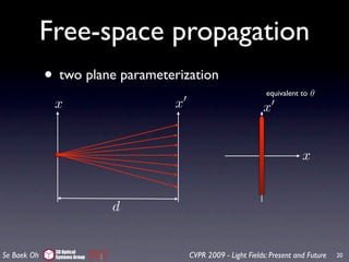
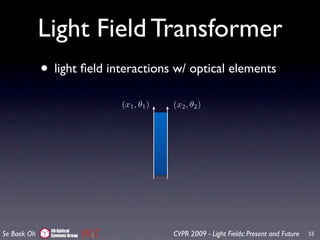
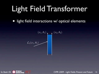
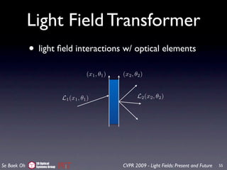
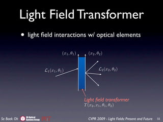
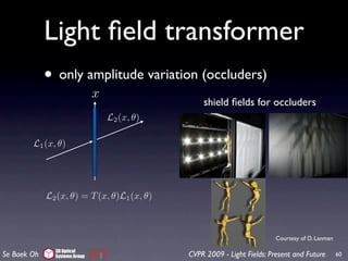
4D LF Transformer
•
Figure 7: Concept of virtual light sources for coherent light.
w/ anglethe LF representation, no interference is predicted. By
In shift invariant elements (in the
paraxial region) virtual light sources, the LF propagation still
including the
n for diffraction
• can be used.
ould be included. e.g. aperture, lens, thin grating, etc
oducing the con-
have negative ra-
es at a and b as
al light source is
π[a − b] λ along
θ
by integrating the
l light sources do
ne, which agrees
Once the virtual L2 (x, θ) = T (x, θ − θ)L1 (x, θ )dθ
propagation still Figure 8: Angle shift invariance in a thin transparency. In
erly modeled3Dby Group (a) and (b), the output rays rotate in the same fashion 59
Se Baek Oh Optical
Systems CVPR 2009 - Light Fields: Present and Future as](https://image.slidesharecdn.com/alfwdf-090708133459-phpapp01/85/Augmenting-Light-Field-132-320.jpg)
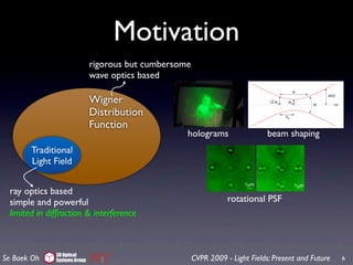
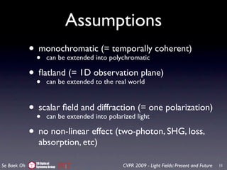
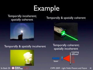
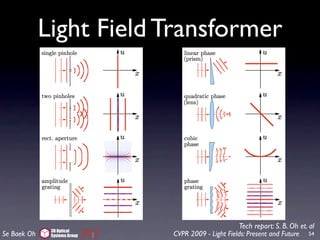
![Applications
On
wavefront coding holography 315
rendering
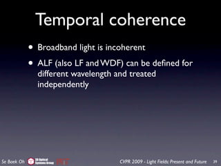
the screen was very large. As expected, we see (Fig. 9) th
Fraunhofer diffraction pattern.
1.1. Double-helix point spread function (DH-PSF)
A DH-PSF system can be implemented by introducing a phase mask in the Fourier plane of an
otherwise standard imaging system. The phase mask is designed such that its transmittance
function generates a rotating pattern in the focal region of a Fourier transform lens [15-18].
Specifically, the DH-PSF exhibits two lobes that spin around the opticalaperture. An animate
Figure 9: Diffraction from a square axis as shown in Fig.
1(a). Note that DH-PSF displays this experiment with of orientation with defocusappears in
of a significant change varying the aperture size over an
gaussian beam rotating PSF
extended depth. In contrast, the standard PSF presents a slowly changing and expanding
plementary material as a video. The distance from the ap
symmetrical pattern throughout the same region [Fig. 1(b)].
the screen is 1 m.
316
317 Double rectangular apertures: Next we created two r
lar apertures and probe them with the AMP. Note that we
3D Optical Fig. 1. Comparison of the (a) DH-PSF and the (b) standard PSF at different axial planes for a
Se Baek Oh Systems Group CVPR 2009 - Light Fields: Present and Future
system with 0.45 numerical aperture (NA) and 633nm wavelength. 61](https://image.slidesharecdn.com/alfwdf-090708133459-phpapp01/85/Augmenting-Light-Field-134-320.jpg)