Download as PDF, PPTX

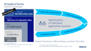

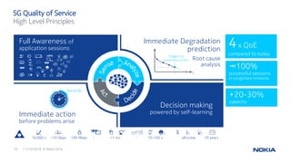

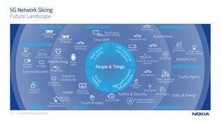


The document discusses the advancements and architecture of 5G technology, highlighting its enhanced quality of service, network slicing, and reduced latency compared to LTE. It details the need for dynamic and adaptive QoS management to support a wide variety of applications with differing requirements, as well as the expected evolution of 5G network capabilities. The importance of a flexible architecture to efficiently support new business needs and the increasing complexity of network environments is also addressed.