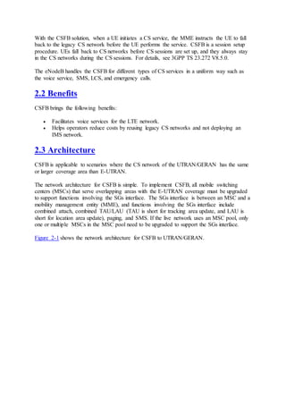
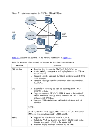
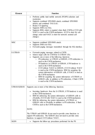
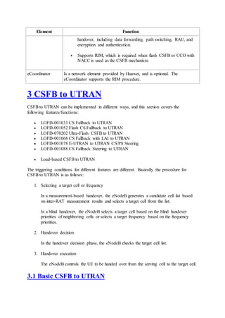
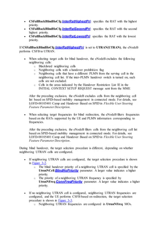
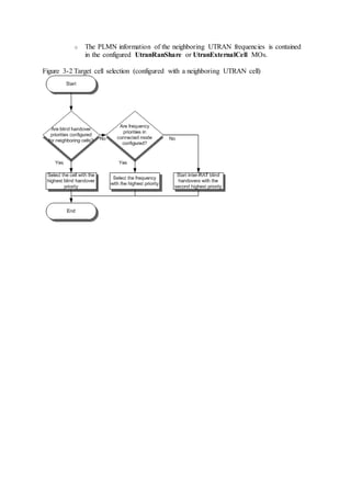
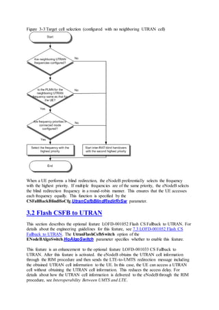
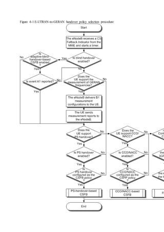
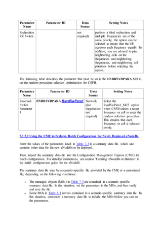
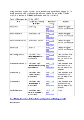
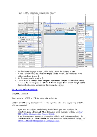
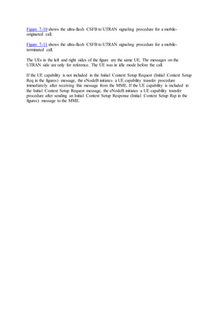
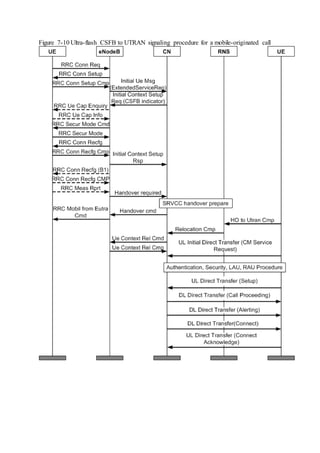
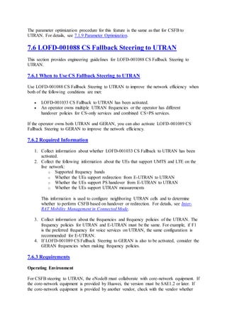
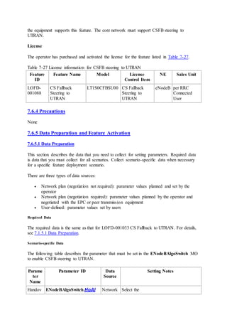
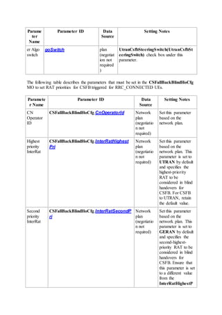
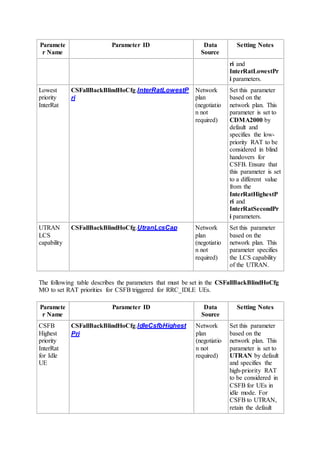
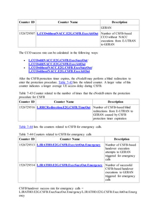
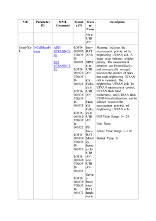
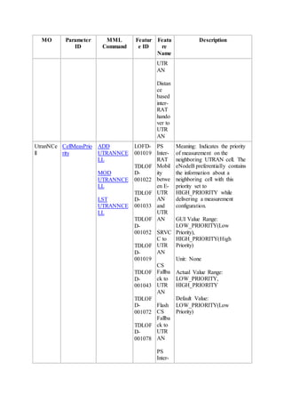
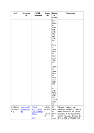
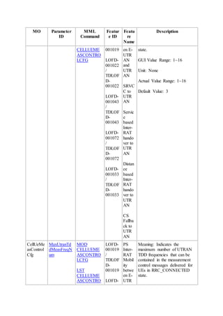
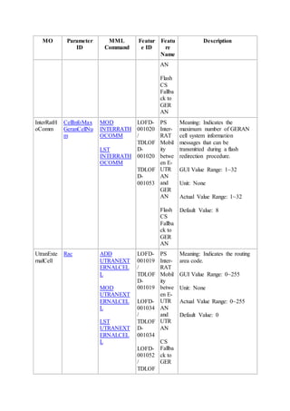
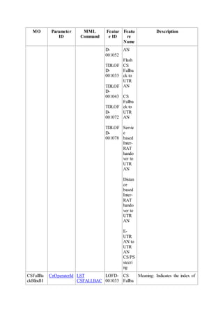
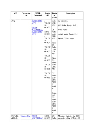
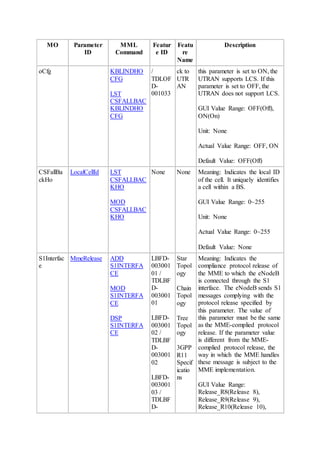
Downloaded 470 times

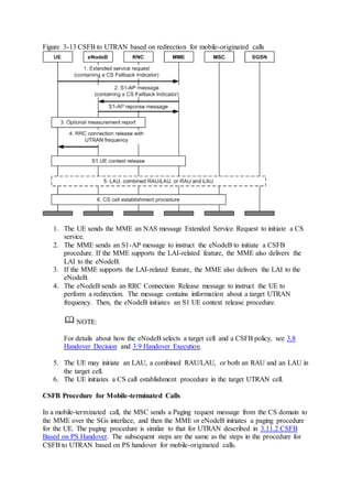
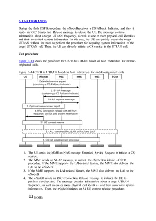
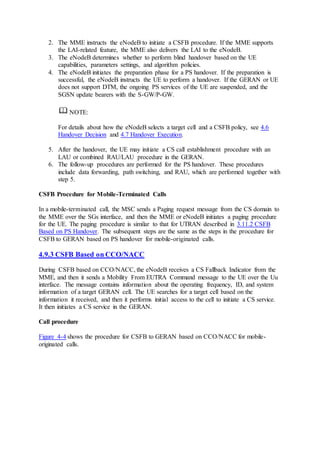
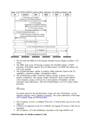
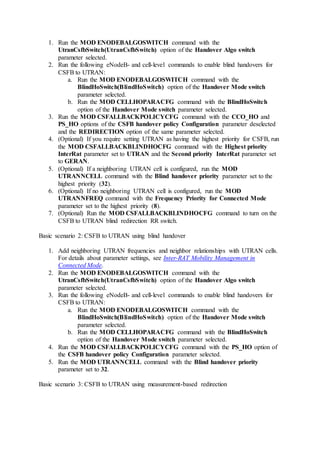
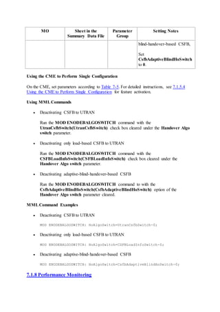
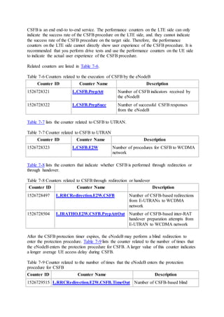
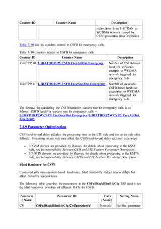
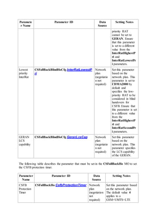
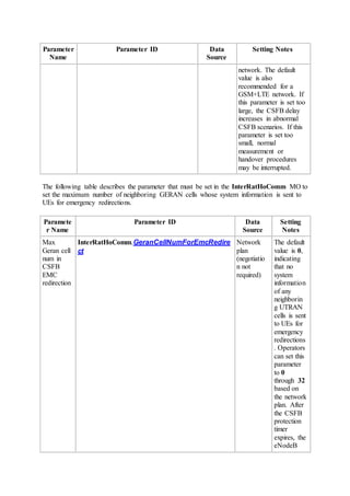
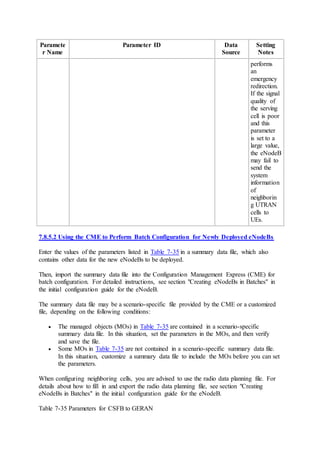
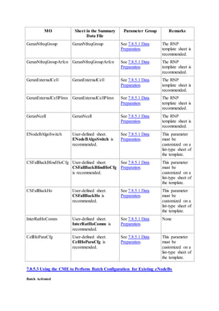
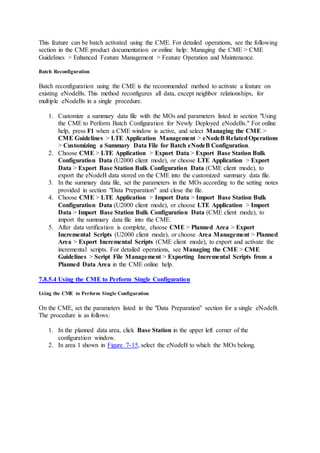
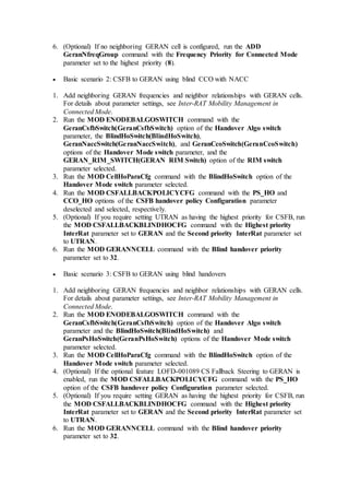
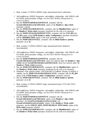
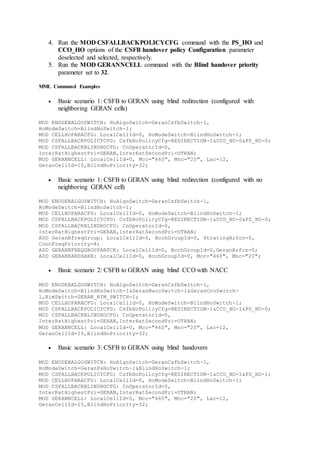
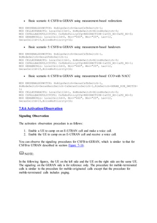
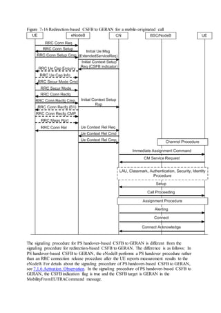
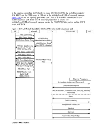
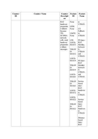
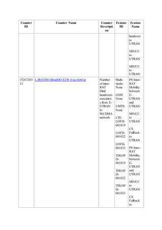
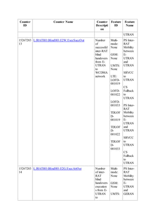
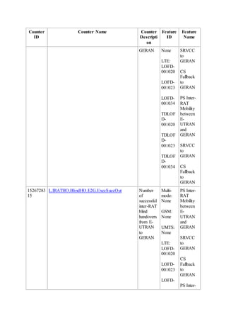
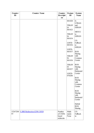
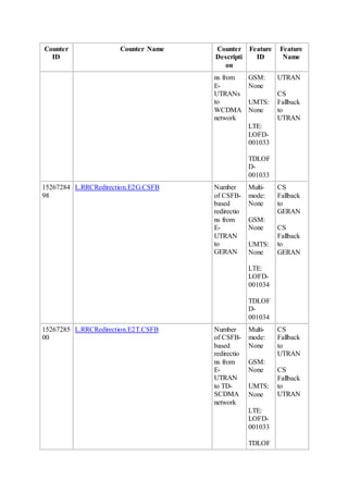
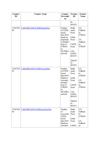
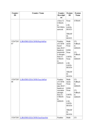

This document provides an overview and detailed descriptions of Circuit Switched Fallback (CSFB) features in an evolved Radio Access Network (eRAN). It describes CSFB procedures for falling back from an LTE network to UTRAN or GERAN networks to support circuit switched services like voice calls. The document includes sections on CSFB architectures, handover decisions and executions, related interfaces, engineering guidelines, parameters and troubleshooting.