Downloaded 430 times


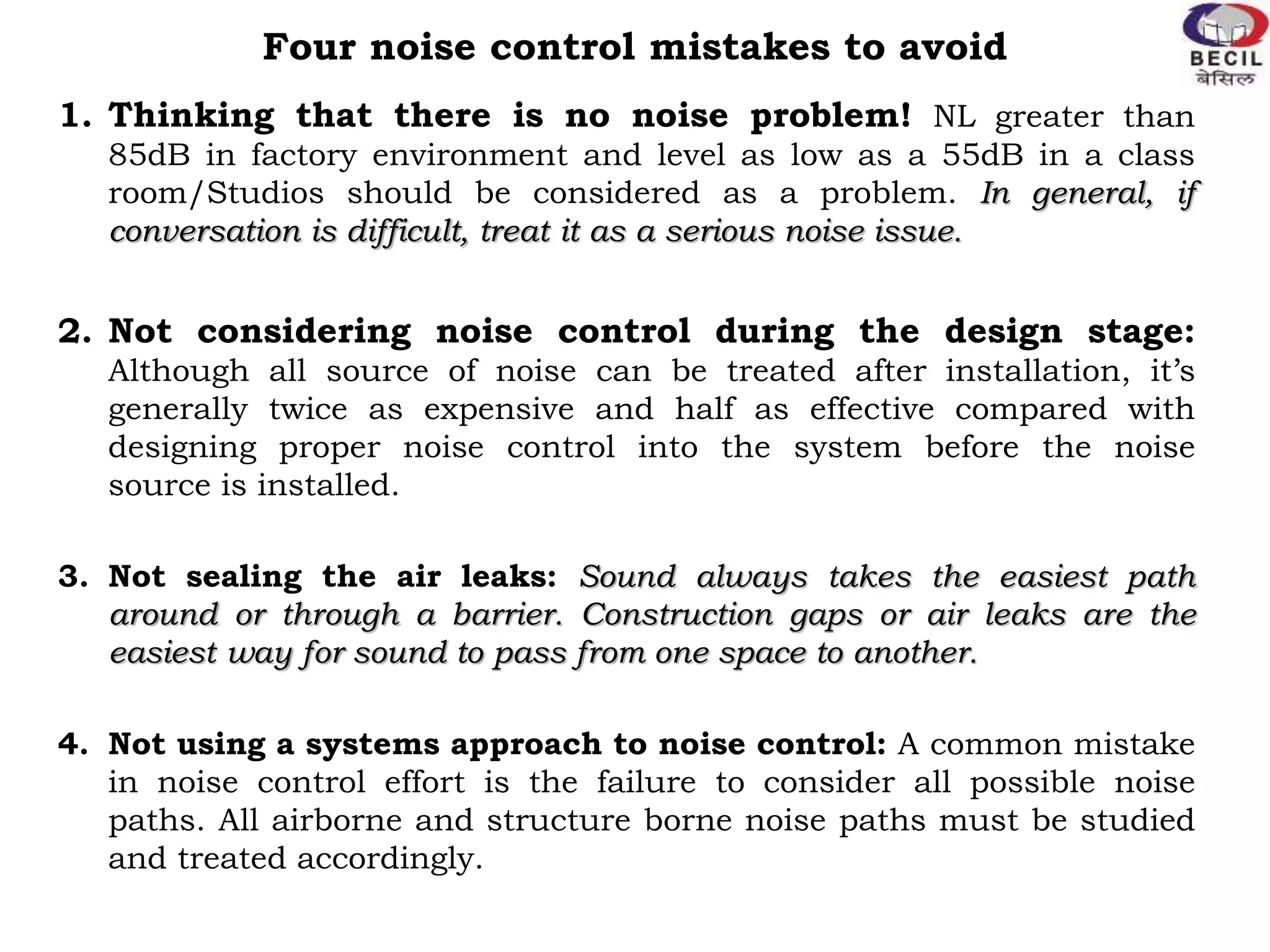


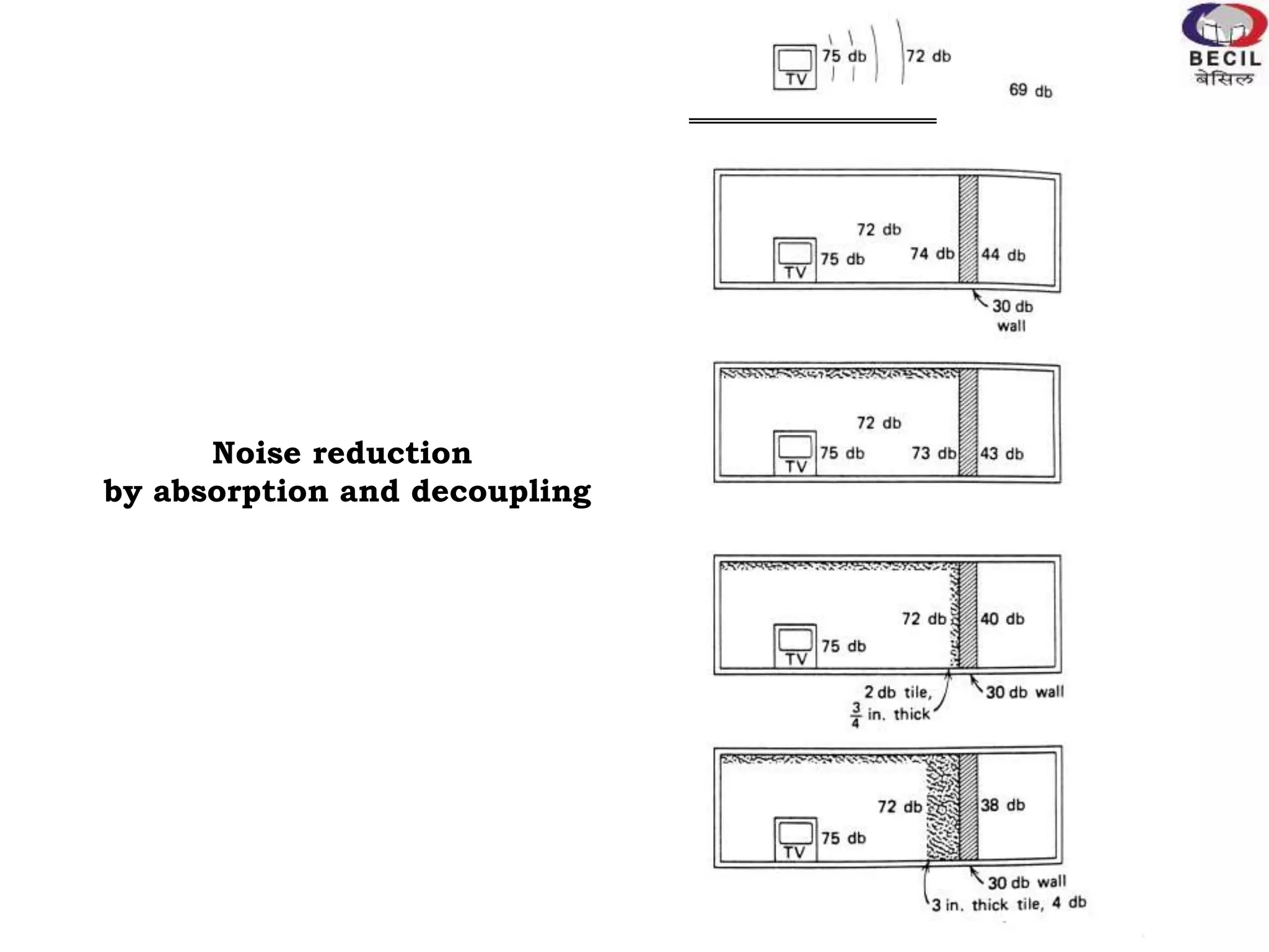


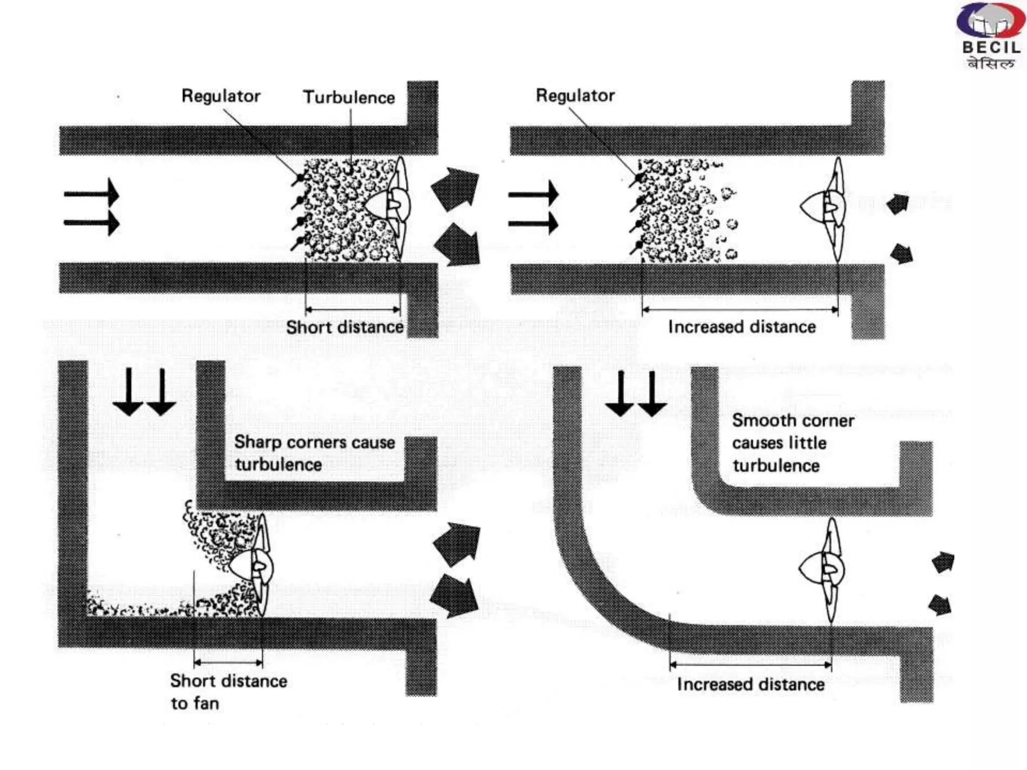


This document discusses noise control measures for HVAC systems. It begins by outlining the effects of noise on humans and some common mistakes in noise control. It then describes basic noise control methods like absorption, damping, decoupling, mass, and flow control. Specific examples of decoupling measures like resilient channels, clips, and hangers are provided. The document also includes a case study of noise control applied to an HVAC system, identifying common noise sources and effective control approaches like equipment location, sealing, isolation, attenuation, and ductwork design. Active noise control is discussed as a supplement to traditional passive methods.