Download to read offline
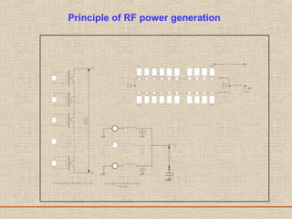

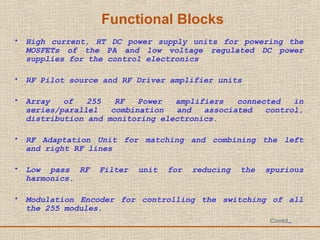
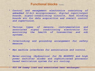
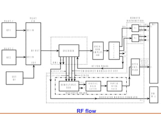
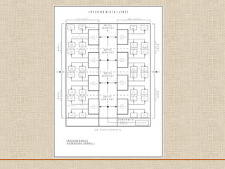
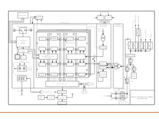
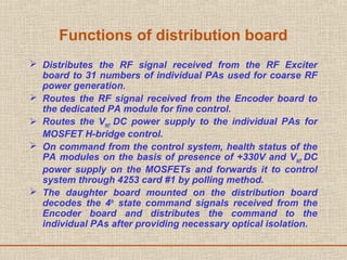
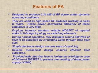

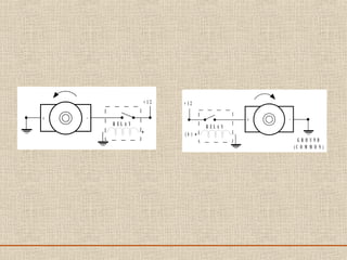
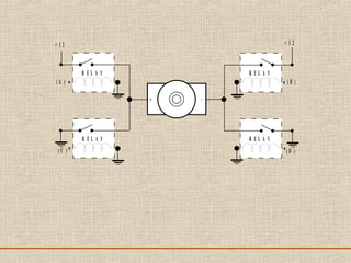
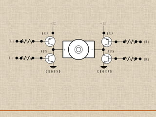
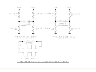
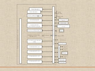
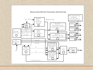
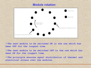

The document discusses a presentation about a 300 kW MW transmitter by R.Narasimha Swamy. It describes how RF power is generated by connecting RF amplifier modules in series and parallel combinations. The functional blocks of the transmitter include a high voltage DC power supply, RF driver amplifier, 255 RF power amplifiers arranged on racks, an RF adaptation unit, filter, and control electronics. It also discusses the principles of serial, parallel and mixed combinations of modules and provides examples of Thales solutions.


![Fundamentals of power electronics [presentation slides] 2nd ed r. erickson ww](https://cdn.slidesharecdn.com/ss_thumbnails/fundamentalsofpowerelectronicspresentationslides2nded-r-ericksonww-100522135011-phpapp02-thumbnail.jpg?width=640&height=640&fit=bounds)


