The document discusses the impact of the COVID-19 pandemic while introducing a project on Automatic Power Factor Correction (APFC) using Arduino technology. It covers various aspects such as the importance of power factor, hardware and software components of the project, and the methodology for improving power factor through capacitors. Additionally, it highlights the advantages and disadvantages of the proposed solution while providing achievements of the project phases.
![CONTENTS
• Introduction
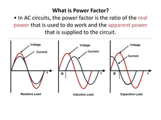
• What is Power Factor?
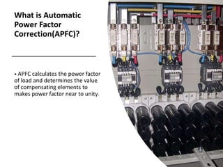
• What is Automatic Power Factor Correction(APFC)?
• Why Power Factor Should be Corrected?
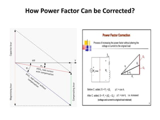
• How Power Factor Can be Corrected?
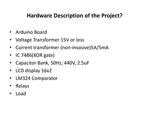
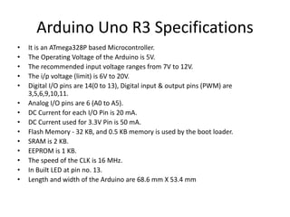
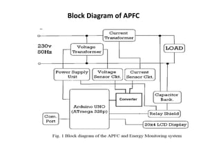
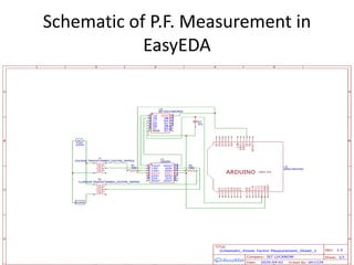
• Hardware Description of Project
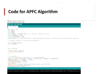
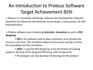
• Software Description of Project
• How We Execute The Project?
• ADVANTAGES of APFC
• DISADVANTAGES
• TARGET ACHIEVEMENT ROUND-1 [95% achieved]- Slide 23
• TARGET ACHIEVEMENT ROUND-2 [80% achieved]- Slide 26](https://image.slidesharecdn.com/apfcslideshare-201104075618/85/Automatic-Power-Factor-Correction-Using-Arduino-Uno-3-320.jpg)