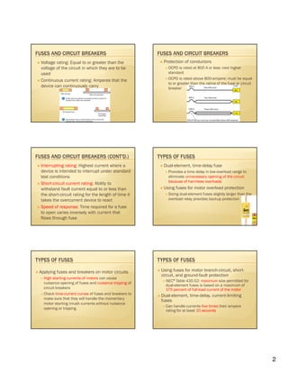
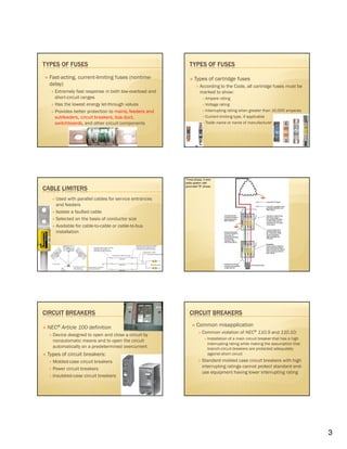
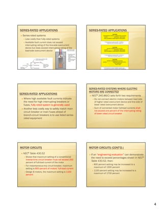
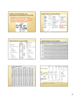
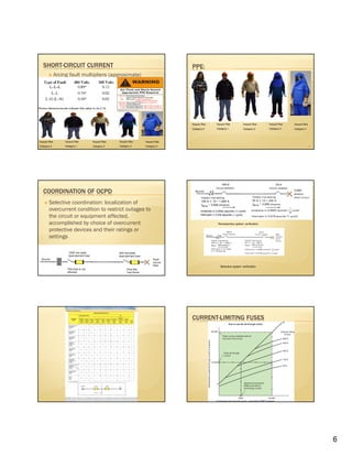
1
Overcurrent Protection:
Fuses & Circuit Breakers
ELECTRICAL SAFETY
Safe Design & Const.Safe Design & Const.Safe Design & Const.Safe Design & Const.
2Safe Work PracticeSafe Maintenance
Safe Equipment
OVERCURRENT PROTECTION
NEC240 states the requirements for OCPD
NEC® 240.1 (FPN): use if the current reaches a
value that will cause excessive temperature in
conductors or conductor insulation
OVERCURRENT PROTECTION
UL and NEMA establish standards for ratings,
types, classifications, and testing procedures
for fuses and circuit breakers
DISCONNECT SWITCHES
Fused switches are available in ratings of 30-
6000A in both 250 and 600 volts
Used with copper conductors unless marked to
indicate suitability for use with aluminum
Rating, unless otherwise marked, is based on
(NEC110.14):
140°F (60°C)------ wire (14 -1 AWG)
167°F (75°C)------wires 1/0 AWG & larger
May be equipped with ground-fault sensing and
labels that indicate their intended use
DISCONNECT SWITCHES
Occupants must have access to OCPD for their
circuits, NEC 240.24(B)
OCPD must be readily accessible NEC
240.24(A)
2
FUSES AND CIRCUIT BREAKERS
Voltage rating: Equal to or greater than the
voltage of the circuit in which they are to be
used
Continuous current rating: Amperes that the
device can continuously carry
FUSES AND CIRCUIT BREAKERS
Protection of conductors
OCPD is rated at 800 A or less: next higher
standard
OCPD is rated above 800-ampere: must be equal
to or greater than the rating of the fuse or circuit
breaker
FUSES AND CIRCUIT BREAKERS (CONT'D.)
Interrupting rating: Highest current where a
device is intended to interrupt under standard
test conditions
Short-circuit current rating: Ability to
withstand fault current equal to or less than
the short-circuit rating for the length of time it
takes the overcurrent device to react
Speed of response: Time required for a fuse
to open varies inversely with current that
flows through fuse
TYPES OF FUSES
Dual-element, time-delay fuse
Provides a time delay in low-overload range to
eliminate unnecessary opening of the circuit
because of harmless overloads
Using fuses for motor overload protection
Sizing dual-element fuses slightly larger than the
overload relay provides backup protection
TYPES OF FUSES
Applying fuses and breakers on motor circuits
High starting currents of motors can cause
nuisance opening of fuses and nuisance tripping of
circuit breakers
Check time-current curves of fuses and breakers to
make sure that they will handle the momentary
motor starting inrush currents without nuisance
opening or tripping
TYPES OF FUSES
Using fuses for motor branch-circuit, short-
circuit, and ground-fault protection
NEC® Table 430.52: maximum size permitted for
dual-element fuses is based on a maximum of
175 percent of full-load current of the motor
Dual-element, time-delay, current-limiting
fuses
Can handle currents five times their ampere
rating for at least 10 seconds
3
TYPES OF FUSES
Fast-acting, current-limiting fuses (nontime-
delay)
Extremely fast response in both low-overload and
short-circuit ranges
Has the lowest energy let-through values
Provides better protection to mains, feeders and
subfeeders, circuit breakers, bus duct,
switchboards, and other circuit components
TYPES OF FUSES
Types of cartridge fuses
According to the Code, all cartridge fuses must be
marked to show:
Ampere rating
Voltage rating
Interrupting rating when greater than 10,000 amperes
Current-limiting type, if applicable
Trade name or name of manufacturer
CABLE LIMITERS
Used with parallel cables for service entrances
and feeders
Isolate a faulted cable
Selected on the basis of conductor size
Available for cable-to-cable or cable-to-bus
installation
Three-phase, 3-wire
delta system with
grounded “B” phase
CIRCUIT BREAKERS
NEC® Article 100 definition
Device designed to open and close a circuit by
nonautomatic means and to open the circuit
automatically on a predetermined overcurrent
Types of circuit breakers:
Molded-case circuit breakers
Power circuit breakers
Insulated-case circuit breakers
CIRCUIT BREAKERS
Common misapplication
Common violation of NEC® 110.9 and 110.10:
Installation of a main circuit breaker that has a high
interrupting rating while making the assumption that
branch-circuit breakers are protected adequately
against short circuit
Standard molded case circuit breakers with high
interrupting ratings cannot protect standard end-
use equipment having lower interrupting rating
4
SERIES-RATED APPLICATIONS
Series-rated systems
Less costly than fully-rated systems
Available fault current does not exceed
interrupting rating of the line-side overcurrent
device but does exceed interrupting rating of the
load-side overcurrent device
SERIES-RATED APPLICATIONS
Where high available fault currents indicate
the need for high interrupting breakers or
fuses, fully rated system is generally used
Another less costly way to safely match main
circuit breaker or main fuses ahead of
branch-circuit breakers is to use listed series-
rated equipment
SERIES-RATED SYSTEMS WHERE ELECTRIC
MOTORS ARE CONNECTED
NEC® 240.86(C) sets forth two requirements
Do not connect electric motors between load side
of higher rated overcurrent device and line side of
lower rated overcurrent device
Sum of connected motor full-load currents shall
not exceed one percent of the interrupting rating
of lower rated circuit breaker
MOTOR CIRCUITS
NEC® Table 430.52
Shows that maximum setting of a conventional
inverse-time circuit breaker must not exceed 250
percent of full-load current of the motor
For instantaneous-trip circuit breaker, maximum
setting is 800 percent of motors’ full-load current
Design B motors, the maximum setting is 1100
percent
MOTOR CIRCUITS (CONT'D.)
If an “engineering evaluation” can demonstrate
the need to exceed percentages shown in NEC®
Table 430.52, then:
800 percent setting may be increased to a
maximum of 1300 percent
1100 percent setting may be increased to a
maximum of 1700 percent
5
HEATING, AIR-CONDITIONING, AND
REFRIGERATION OVERCURRENT PROTECTION
Nameplate on HVAC equipment might
indicate “maximum size fuse,” “maximum
size fuse or circuit breaker,” or “maximum
size fuse or HACR circuit breaker”
SHORT-CIRCUIT CALCULATIONS
3-Phase Fault
Current
Calculation
SHORT-CIRCUIT CALCULATIONS SHORT-CIRCUIT CALCULATIONS
29
Electrical system for a Commercial Building
6
SHORT-CIRCUIT CURRENT
Arcing fault multipliers (approximate)
Hazard Risk
Category 0
Hazard Risk
Category 1
Hazard Risk
Category 2
Hazard Risk
Category 3
Hazard Risk
Category 4
PPE:
32
Hazard Risk
Category 0
Hazard Risk
Category 1
Hazard Risk
Category 2
Hazard Risk
Category 3
Hazard Risk
Category 4
COORDINATION OF OCPD
Selective coordination: localization of
overcurrent condition to restrict outages to
the circuit or equipment affected,
accomplished by choice of overcurrent
protective devices and their ratings or
settings
Nonselective system verification
Selective system verification
Nonselective system verification
CURRENT-LIMITING FUSES
7
CURRENT-LIMITING FUSES CURRENT-LIMITING FUSES
CURRENT-LIMITING FUSES

Ocpd 07-23-13

  • 1.
    1 Overcurrent Protection: Fuses &Circuit Breakers ELECTRICAL SAFETY Safe Design & Const.Safe Design & Const.Safe Design & Const.Safe Design & Const. 2Safe Work PracticeSafe Maintenance Safe Equipment OVERCURRENT PROTECTION NEC240 states the requirements for OCPD NEC® 240.1 (FPN): use if the current reaches a value that will cause excessive temperature in conductors or conductor insulation OVERCURRENT PROTECTION UL and NEMA establish standards for ratings, types, classifications, and testing procedures for fuses and circuit breakers DISCONNECT SWITCHES Fused switches are available in ratings of 30- 6000A in both 250 and 600 volts Used with copper conductors unless marked to indicate suitability for use with aluminum Rating, unless otherwise marked, is based on (NEC110.14): 140°F (60°C)------ wire (14 -1 AWG) 167°F (75°C)------wires 1/0 AWG & larger May be equipped with ground-fault sensing and labels that indicate their intended use DISCONNECT SWITCHES Occupants must have access to OCPD for their circuits, NEC 240.24(B) OCPD must be readily accessible NEC 240.24(A)
  • 2.
    2 FUSES AND CIRCUITBREAKERS Voltage rating: Equal to or greater than the voltage of the circuit in which they are to be used Continuous current rating: Amperes that the device can continuously carry FUSES AND CIRCUIT BREAKERS Protection of conductors OCPD is rated at 800 A or less: next higher standard OCPD is rated above 800-ampere: must be equal to or greater than the rating of the fuse or circuit breaker FUSES AND CIRCUIT BREAKERS (CONT'D.) Interrupting rating: Highest current where a device is intended to interrupt under standard test conditions Short-circuit current rating: Ability to withstand fault current equal to or less than the short-circuit rating for the length of time it takes the overcurrent device to react Speed of response: Time required for a fuse to open varies inversely with current that flows through fuse TYPES OF FUSES Dual-element, time-delay fuse Provides a time delay in low-overload range to eliminate unnecessary opening of the circuit because of harmless overloads Using fuses for motor overload protection Sizing dual-element fuses slightly larger than the overload relay provides backup protection TYPES OF FUSES Applying fuses and breakers on motor circuits High starting currents of motors can cause nuisance opening of fuses and nuisance tripping of circuit breakers Check time-current curves of fuses and breakers to make sure that they will handle the momentary motor starting inrush currents without nuisance opening or tripping TYPES OF FUSES Using fuses for motor branch-circuit, short- circuit, and ground-fault protection NEC® Table 430.52: maximum size permitted for dual-element fuses is based on a maximum of 175 percent of full-load current of the motor Dual-element, time-delay, current-limiting fuses Can handle currents five times their ampere rating for at least 10 seconds
  • 3.
    3 TYPES OF FUSES Fast-acting,current-limiting fuses (nontime- delay) Extremely fast response in both low-overload and short-circuit ranges Has the lowest energy let-through values Provides better protection to mains, feeders and subfeeders, circuit breakers, bus duct, switchboards, and other circuit components TYPES OF FUSES Types of cartridge fuses According to the Code, all cartridge fuses must be marked to show: Ampere rating Voltage rating Interrupting rating when greater than 10,000 amperes Current-limiting type, if applicable Trade name or name of manufacturer CABLE LIMITERS Used with parallel cables for service entrances and feeders Isolate a faulted cable Selected on the basis of conductor size Available for cable-to-cable or cable-to-bus installation Three-phase, 3-wire delta system with grounded “B” phase CIRCUIT BREAKERS NEC® Article 100 definition Device designed to open and close a circuit by nonautomatic means and to open the circuit automatically on a predetermined overcurrent Types of circuit breakers: Molded-case circuit breakers Power circuit breakers Insulated-case circuit breakers CIRCUIT BREAKERS Common misapplication Common violation of NEC® 110.9 and 110.10: Installation of a main circuit breaker that has a high interrupting rating while making the assumption that branch-circuit breakers are protected adequately against short circuit Standard molded case circuit breakers with high interrupting ratings cannot protect standard end- use equipment having lower interrupting rating
  • 4.
    4 SERIES-RATED APPLICATIONS Series-rated systems Lesscostly than fully-rated systems Available fault current does not exceed interrupting rating of the line-side overcurrent device but does exceed interrupting rating of the load-side overcurrent device SERIES-RATED APPLICATIONS SERIES-RATED APPLICATIONS Where high available fault currents indicate the need for high interrupting breakers or fuses, fully rated system is generally used Another less costly way to safely match main circuit breaker or main fuses ahead of branch-circuit breakers is to use listed series- rated equipment SERIES-RATED SYSTEMS WHERE ELECTRIC MOTORS ARE CONNECTED NEC® 240.86(C) sets forth two requirements Do not connect electric motors between load side of higher rated overcurrent device and line side of lower rated overcurrent device Sum of connected motor full-load currents shall not exceed one percent of the interrupting rating of lower rated circuit breaker MOTOR CIRCUITS NEC® Table 430.52 Shows that maximum setting of a conventional inverse-time circuit breaker must not exceed 250 percent of full-load current of the motor For instantaneous-trip circuit breaker, maximum setting is 800 percent of motors’ full-load current Design B motors, the maximum setting is 1100 percent MOTOR CIRCUITS (CONT'D.) If an “engineering evaluation” can demonstrate the need to exceed percentages shown in NEC® Table 430.52, then: 800 percent setting may be increased to a maximum of 1300 percent 1100 percent setting may be increased to a maximum of 1700 percent
  • 5.
    5 HEATING, AIR-CONDITIONING, AND REFRIGERATIONOVERCURRENT PROTECTION Nameplate on HVAC equipment might indicate “maximum size fuse,” “maximum size fuse or circuit breaker,” or “maximum size fuse or HACR circuit breaker” SHORT-CIRCUIT CALCULATIONS 3-Phase Fault Current Calculation SHORT-CIRCUIT CALCULATIONS SHORT-CIRCUIT CALCULATIONS 29 Electrical system for a Commercial Building
  • 6.
    6 SHORT-CIRCUIT CURRENT Arcing faultmultipliers (approximate) Hazard Risk Category 0 Hazard Risk Category 1 Hazard Risk Category 2 Hazard Risk Category 3 Hazard Risk Category 4 PPE: 32 Hazard Risk Category 0 Hazard Risk Category 1 Hazard Risk Category 2 Hazard Risk Category 3 Hazard Risk Category 4 COORDINATION OF OCPD Selective coordination: localization of overcurrent condition to restrict outages to the circuit or equipment affected, accomplished by choice of overcurrent protective devices and their ratings or settings Nonselective system verification Selective system verification Nonselective system verification CURRENT-LIMITING FUSES
  • 7.
    7 CURRENT-LIMITING FUSES CURRENT-LIMITINGFUSES CURRENT-LIMITING FUSES