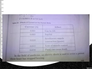
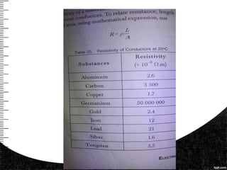
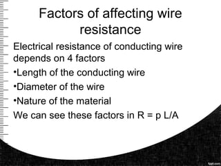
The document provides a detailed explanation of how to use multimeters, including both analog and digital types, and how to read and measure electrical quantities like voltage, current, and resistance. It includes guidelines for proper usage, understanding of scales, and formulas for calculating resistance based on wire properties. Additionally, it discusses factors affecting resistance and temperature's impact on wire performance, along with example computations and quizzes for learning assessment.


![• Last factor is the temperature of the wire
We can see this factor in R = R ref [1 + (T-
T ref)].](https://image.slidesharecdn.com/multitester-160925131140/85/Multitester-Wire-resistivity-132-320.jpg)
![• We will use this formula for determining
the resistance of a wire R = R ref [1 + (T
-T ref)].
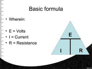
• Where in :
• R ref is the resistance initial or reference
• Temperature Coefficient of resistance
for the conductor material
• T is the given temperature
• T ref is temperature initial or reference](https://image.slidesharecdn.com/multitester-160925131140/85/Multitester-Wire-resistivity-145-320.jpg)
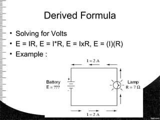
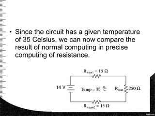
![• Step 1 : gather the given value in
the circuit R = R ref [1 + (T -T ref)].
• Wire 1 is 15 ohms (Material: copper)
• Wire 2 is 15 ohms
• T is 35 Celsius
• R load 250 ohms
• V 14volts
• = 0.004041
35](https://image.slidesharecdn.com/multitester-160925131140/85/Multitester-Wire-resistivity-146-320.jpg)
![• Step 2 Solve each resistance to see the
effect of the temperature.
• Solving for wire 1 and 2
• R = R ref [1 + (T -T ref)].
• R = 15 ohms [1+0.004041(35 Celsius – 20
Celsius)]](https://image.slidesharecdn.com/multitester-160925131140/85/Multitester-Wire-resistivity-148-320.jpg)
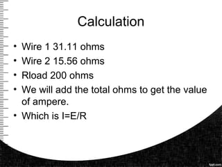
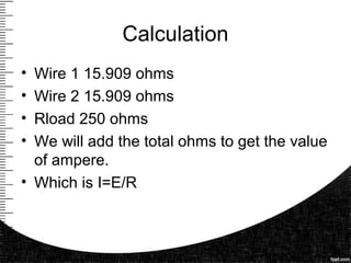
![Calculation
• R = 15 ohms [1+0.004041(35 Celsius – 20
Celsius)]
• R= 15 ohms [1+0.004041(15Celsius)]
• R = 15 ohms [1+0.060615]
• R = 15 ohms*1.060615
• R = 15.909 ohms](https://image.slidesharecdn.com/multitester-160925131140/85/Multitester-Wire-resistivity-149-320.jpg)


![• We will use this formula for determining
the resistance of a wire R = R ref [1 + (T
-T ref)].
• Where in :
• R ref is the resistance initial or reference
• Temperature Coefficient of resistance
for the conductor material
• T is the given temperature
• T ref is temperature initial or reference](https://image.slidesharecdn.com/multitester-160925131140/85/Multitester-Wire-resistivity-161-320.jpg)
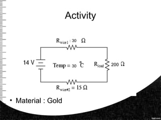
![• Step 1 : gather the given value in
the circuit R = R ref [1 + (T -T ref)].
• Wire 1 is 30 ohms (Material: Gold)
• Wire 2 is 15 ohms
• T is 30 Celsius
• R load 200 ohms
• V 14volts
• = 0.003715](https://image.slidesharecdn.com/multitester-160925131140/85/Multitester-Wire-resistivity-162-320.jpg)

![• Step 2 Solve each resistance to see the
effect of the temperature.
• Solving for wire 1
• R = R ref [1 + (T -T ref)].
• R = 30 ohms [1+0.003715(30 Celsius – 20
Celsius)]](https://image.slidesharecdn.com/multitester-160925131140/85/Multitester-Wire-resistivity-164-320.jpg)
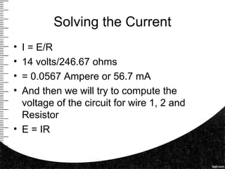
![Calculation
• R = 30 ohms [1+0.003715 (30 Celsius –
20 Celsius)]
• R= 30 ohms [1+0.003715 (10Celsius)]
• R = 30 ohms [1+0.03715]
• R = 30 ohms*1.03715
• R = 31.11 ohms wire 1](https://image.slidesharecdn.com/multitester-160925131140/85/Multitester-Wire-resistivity-165-320.jpg)
![• Step 2 Solve each resistance to see the
effect of the temperature.
• Solving for wire 2
• R = R ref [1 + (T -T ref)].
• R = 15 ohms [1+0.003715(30 Celsius – 20
Celsius)]](https://image.slidesharecdn.com/multitester-160925131140/85/Multitester-Wire-resistivity-166-320.jpg)
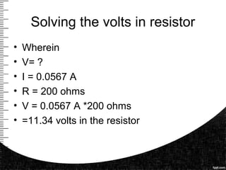
![Calculation
• R = 15 ohms [1+0.003715(30 Celsius – 20
Celsius)]
• R= 15 ohms [1+0.003715(10Celsius)]
• R = 15 ohms [1+0.03715]
• R = 15 ohms*1.03715
• R = 15.56 ohms wire 2](https://image.slidesharecdn.com/multitester-160925131140/85/Multitester-Wire-resistivity-167-320.jpg)