Download as PDF, PPTX


![V(x)
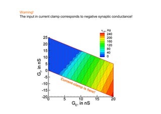
r Внутри V(x+Δx)
jm
C
im
g S (V VL ) iS
φ≈0
Снаружи
h
VNa V
gNa
gK
Vrest
VK
[Покровский, 1978]](https://image.slidesharecdn.com/lekciya1dc-100822150900-phpapp01/85/Neuron-computer-interface-in-Dynamic-Clamp-experiments-5-320.jpg)
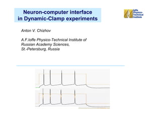
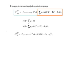
![Model of a pyramidal neuron
dV
C I Na I DR I A I M I H I L I AHP iS
dt
p q
E X P Е R I М Е N Т
I ... g... x (t ) y (t ) (V (t ) V... )
dx x (U ) x
,
dt x (U )
dy y (U ) y
dt y (U )
Approximations for I Na , I DR , I A , I M , I H
are taken from [L.Graham, 1999]; IAHP is
from [N.Kopell et al., 2000]
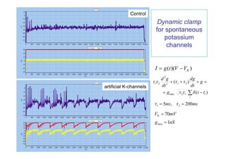
Model with noise
Color noise model for
synaptic current IS is the
Ornstein-Uhlenbeck process:
diS 0
iS (t ) iS 2 (t )
dt](https://image.slidesharecdn.com/lekciya1dc-100822150900-phpapp01/85/Neuron-computer-interface-in-Dynamic-Clamp-experiments-7-320.jpg)
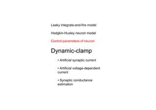
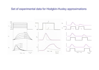
![E X P E R I M E N T
Control parameters of
a neuron
dV ( t )
C g Na m 3 (V , t )h (V , t )(V (t ) VNa )
dt
4 2V
g K n (V , t )(V (t ) VK ) g L (V ( t ) VL ) iS k 2
x
Voltage-gated channels kinetics:
dm m (V ) m
MODEL
dt m (V )
dh h (V ) h [Hodgkin, Huxley, 1952]
dt h (V )
dn n (V ) n
dt n (V )
Property: Neuron is controlled by two parameters
[Покровский, 1978]
iS GE (V VE ) GI (V VI ) I electrode s (V V0 ) u
u GE (VE V0 ) GI (VI V0 ) I electrode
s GE GI](https://image.slidesharecdn.com/lekciya1dc-100822150900-phpapp01/85/Neuron-computer-interface-in-Dynamic-Clamp-experiments-8-320.jpg)
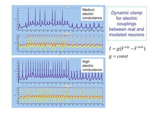
![Dynamic clamp for synaptic current
[Sharp AA, O'Neil MB, Abbott LF, Marder E. Dynamic clamp: computer-generated
conductances in real neurons. // J.Neurophysiol. 1993, 69(3):992-5]
I g GABA (t ) (V VGABA )
gGABA (t ) gGABA e t / 1 e t / 2 , 1 5 s, 2 15 s, gGABA 8 nS
max max](https://image.slidesharecdn.com/lekciya1dc-100822150900-phpapp01/85/Neuron-computer-interface-in-Dynamic-Clamp-experiments-14-320.jpg)
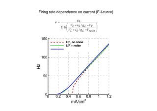
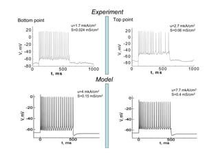
![Dynamic clamp Model [Graham, 1999] for
to study firing properties of CA1 pyramidal neuron
neuron
Hz
0.6 80
Experiment: pyramidal cell 60
of visual cortex 0.5 40
Hz
0.06 Hz 20
0.4
s, mS/cm2
(2.7; 0.06)
110
0.05 100
0
90
0.04 80 0.3
s, mS/cm2
70
60
0.03 50
40 0.2
(1.7; 0.024) 30
0.02 20
0.01
10
0 0.1
0 1 2 3 0 2 4 6 8 10
2 2
u, A/cm u,mkA/cm](https://image.slidesharecdn.com/lekciya1dc-100822150900-phpapp01/85/Neuron-computer-interface-in-Dynamic-Clamp-experiments-16-320.jpg)
![Dynamic clamp for voltage-gated current:
compensation of INaP
Hippocampal Pyramidal Neuron In Vitro
[Vervaeke K, Hu H., Graham L.J., Storm J.F.
Contrasting effects of the persistent Na+
current on neuronal excitability and spike
timing, Neuron, v49, 2006]](https://image.slidesharecdn.com/lekciya1dc-100822150900-phpapp01/85/Neuron-computer-interface-in-Dynamic-Clamp-experiments-20-320.jpg)
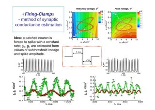
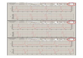
![Dynamic clamp for synaptic conductance
estimations in-vivo
Preferred direction Null direction
V
Эксперимент [Lyle Graham et al.]: Внутриклеточные измерения patch-clamp
в зрительной коре кошки in vivo. Стимул – движущаяся полоска.
V 20 mV
GABAA : GI 10 nS
AMPA : GE 5 nS
1s](https://image.slidesharecdn.com/lekciya1dc-100822150900-phpapp01/85/Neuron-computer-interface-in-Dynamic-Clamp-experiments-22-320.jpg)

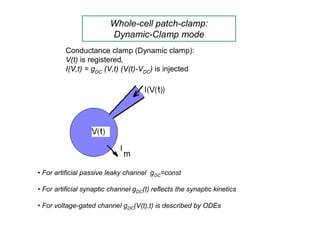
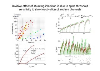
The document discusses neuron-computer interfaces utilizing dynamic-clamp experiments with leaky integrate-and-fire and Hodgkin-Huxley neuron models. It elaborates on the control parameters for neuron dynamic-clamp, the modeling of synaptic and voltage-gated currents, and the implications for neuronal excitability and firing characteristics. The study emphasizes the importance of dynamic clamp for measuring neuronal firing dynamics and estimating synaptic conductances in vivo.


![Circuit Network Analysis - [Chapter4] Laplace Transform](https://cdn.slidesharecdn.com/ss_thumbnails/ch4-150613063858-lva1-app6891-thumbnail.jpg?width=640&height=640&fit=bounds)


![RF Circuit Design - [Ch1-2] Transmission Line Theory](https://cdn.slidesharecdn.com/ss_thumbnails/ch1-2-150613064349-lva1-app6892-thumbnail.jpg?width=640&height=640&fit=bounds)